

Page 1

Installation Guide
for Model 700 Flasher
General Description:
The Code 3® Model 700 Alternating Flasher uses an electronic timing circuit to control two
specially designed flasher relays. The unit is totally weather resistant and may mounted
anywhere on the vehicle away from heat sources, using either the mounting tabs at each end or
the mounting hole through the device. Outputs 1 and 2 are capable of handling up to 100 watts
(8 amps.) each. The model 700 flasher can be used as a Headlight Flasher on non daytime
running lights, hot side switched vehicles, or as a lightbar flasher.
Terminal Functions:
Terminal A - Output 1: 100 watts (8 amps.) maximum load.
Terminal B - Output 2: 100 watts (8 amps.) maximum load.
Terminal c - Flasher On: Activated by + 12VDC.
Applying +12VDC to this terminal through a user supplied switch activates the alternating flash of loads 1 and 2.
Terminal D - Input: To Battery Positive.
Supplies +12VDC to outputs 1 and 2. A user supplied fuse should be installed to protect the outputs. Use at
least 14AWG wire and 20 amp fuse.
Terminal E - To Battery Negative.
Provides ground for the unit.
Terminal F - Steady burn: Activated by +12VDC
Applying +12VDC through a user supplied switch turns both outputs on simultaneously. When removed, the unit
will function normally. This feature will override all other functions.
Terminal G - Pause: Activated by +12VDC.
Applying +12VDC through a user supplied switch turns both outputs off simultaneously. When removed, the unit
will function normally.
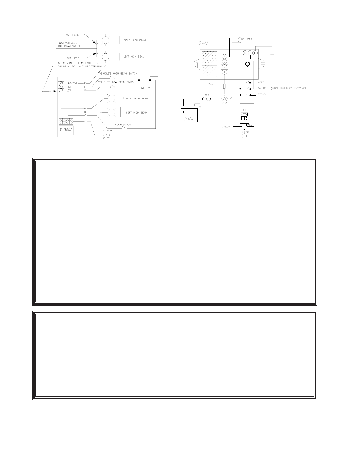
Operation as a Headlight Flasher (12v Operation 0nly):
To operate the Model 700 as a headlight flasher, follow the wiring instructions of Diagram 1.
To operate, apply +12VDC to terminal C through a user supplied switch. This will start the alternating flash.
Now, turn on the vehicle's low beam headlights. The low beam lights should burn steadily. Now. activate the
highbeam switch. High beam lights should now be on. If you do not get these results, recheck all connections
listed above.
If you wish the high beams to continue to flash while the low beams are on, do not connect Terminal G.
See Diagram 1 for additional help.
Operation as a Light Bar Flasher:
To operate the Model 700 as a light bar flasher, jumper Terminal C to Terminal D and connect these to +12VDC
in the bar. Connect one bulb to be flashed to Terminal A and the other bulb to be flashed to Terminal B. Connect
Terminal E to the frame of the light bar to provide ground.
The remaining terminals may be used for special functions when switched to +12VDC. Terminal G will "pause"
or turn off the lamps until power is removed. Terminal F will steady burn the bulbs for use as take down or work
lights until power is removed. See the wiring diagram on the bottom of the unit for further assistance.
1
Page 2
- +
DIAGRAM 1: WIRING DIAGRAM FOR HEAD LIGHT
FLASHER INSTALLATION
DIAGRAM 2: 24v OPERATION
WARRANTY
This product was tested and found to be operational at the time of manufacture. Provided this
product is installed and operated in accordance with the manufacturer's recommendations Code 3, Inc.
guarantees all parts and components except the lamps for a period of 1 year from the date of purchase or delivery, whichever is later. Units demonstrated to be defective within the warranty period will
be repaired or replaced at the factory service center at no cost.
Use of a lamp or other electrical load of a wattage higher than installed or recommended by the
factory, or use of inappropriate or inadequate wiring or circuit protection causes this warranty to
become void. Failure or destruction of the product resulting from abuse or unusual use and/or accidents is not covered by this warranty.
Code 3, Inc. shall in no way be liable for other damages including consequential, indirect or
special damages whether loss is due to negligence or breach of warranty.
CODE 3, INC. MAKES NO OTHER EXPRESS OR IMPLIED WARRANTY INCLUDING, WITHOUT LIMITATION, WARRANTIES OF FITNESS OR MERCHANTABILITY, WITH RESPECT TO
THIS PRODUCT.
PRODUCT RETURNS
In order to provide you with faster service, if you are going to return a product for repair or replacement*, please contact our factory to obtain a Return Goods Authorization Number (RGA number)
before you ship the product to Code 3. Write the RGA number clearly on the package near the mailing
label. Be sure you use sufficient packing materials to avoid damage to the product being returned
while in transit.
*Code 3 reserves the right to repair or replace product at its discretion and assumes no responsibility or liability for
PROBLEMS OR QUESTIONS? CALL OUR TECHNICAL ASSISTANCE HOTLINE (314)996-2800
10986 N. Warson Road
www.code3pse.com
©2005 Code 3, Inc. Printed in USA
Code 3 is a registered trademark of Code 3, Inc. a subsidiary of Public Safety Equipment, Inc.
St. Louis, Missouri 63114-2029—USA
Ph. (314) 426-2700 Fax (314) 426-1337
Revision 10, 11/05- Instruction Book Part No. T01935
2
Code 3, Inc.
 Loading...