

Page 1
INSTALLATION
& OPERATION
MANUAL
MODEL 550
TM
TM
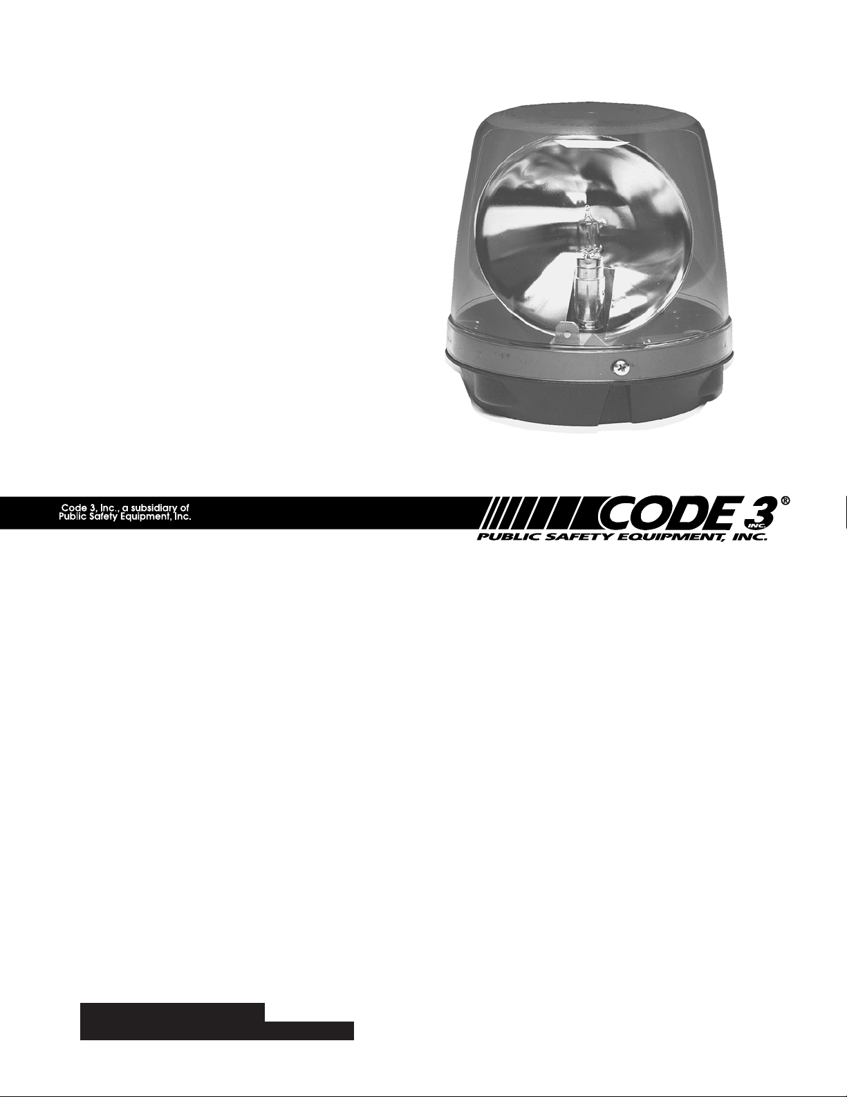
Model 550
REVOLVING BEACON
IMPORTANT:
Contents:
Introduction ......................................................... 2
Unpacking & Pre-Installation .............................. 2
Installation & Mounting ....................................... 2
Wiring Instructions .......................................... 2
Stanchion Mounting ........................................ 3
Magnetic Mounting ......................................... 3
Permanent - Resilient Mounting ..................... 4
Maintenance ....................................................... 5
Parts List (Replacement Parts / Exploded View) 6
Warranty ............................................................. 8
Read all instructions and warnings before installing and using.
INSTALLER:
This manual must be delivered to the end user of this equipment.
Page 2
Introduction
The 550TM beacon has a single rotating warning signal which exceeds by several times the SAE Standards set
for 360 degree rotating warning lights, and is available in permanent, magnetic, or stanchion mount
configurations.
The use of this or any warning device does not insure that all drivers can or will observe or react to an
The use of this or ant warning device does not insure that all drivers can or will observe or react to an
emergency warning signal. Never take the right-of-way for granted. It is your responsibility to be sure you
can proceed safely before entering an intersection, driving against traffic, responding at a high rate of speed,
or walking on or around traffic lanes.
!
WARNING!
The effectiveness of this warning device is highly dependent upon correct mounting and wiring. Read
and follow the manufacturer’s instructions before installing or using this device. The vehicle operator should
insure daily that all features of the device operate correctly. In use, the vehicle operator should insure the
projection of the warning signal is not blocked by vehicle components (i.e.: open trunks or compartment
doors), people, vehicles, or other obstructions.
This equipment is intended for use by authorized personnel only. It is the user’s responsibility to
understand and obey all laws regarding emergency warning devices. The user should check all applicable
city, state and federal laws and regulations.
Code 3, Inc., assumes no liability for any loss resulting from the use of this warning device.
Proper installation is vital to the performance of this warning device and the safe operation of the
emergency vehicle. It is important to recognize that the operator of the emergency vehicle is under psychological and physiological stress caused by the emergency situation. The warning device should be installed
in such a manner as to: A) Not reduce the output performance of the system, B) Place the controls within
convenient reach of the operator so that he can operate the system without losing eye contact with the
roadway.
Emergency warning devices often require high electrical voltages and/or currents. Properly protect and
use caution around live electrical connections. Grounding or shorting of electrical connections can cause
high current arcing, which can cause personal injury and/or severe vehicle damage, including fire.
PROPER INSTALLATION COMBINED WITH OPERATOR TRAINING IN THE PROPER USE OF
EMERGENCY WARNING DEVICES IS ESSENTIAL TO INSURE THE SAFETY OF EMERGENCY PERSONNEL AND THE PUBLIC.
Unpacking & Pre-installation
Carefully remove the beacon and place it on a flat surface, taking care not to scratch the lens.
Examine the unit for transit damage, broken lamps, etc. If it is convenient, you may wish to test the
unit before installation. To test, touch the black wire to ground (earth) and the red wire to +12 volts
D.C. A battery charger may be used for this purpose. If the vehicle has an electrical system other
than 12 volts D.C. negative ground (earth), and you have not ordered a specially wired beacon,
contact your local representative or call the factory for instructions.
Installation & Mounting
Wiring Instructions
The Model 550TM Beacon is designed to operate on a
12 volt D.C. negative ground (earth) system or
alternatively on a 24 volt system when specified.
Use a minimum 16 gauge wire, 14 gauge on
runs longer than 15 ft. Use "SXL" type wire in
the engine compartment. Solder all crimped
connectors and cover with shrink tubing on any
hand splices. DO NOT use insulation displacement
connectors (e.g. 3M® Scotch Lock type connectors).
Connect the ground (earth) lead (black) to the vehicle
chassis, or preferably the negative (earth) terminal of the
battery. Bring the positive lead (red) to the user supplied
control switch, and then to the battery or to the stud on the
battery side of the starter solenoid or alternator. Install a fuse or circuit breaker of 10 amps capacity
in the supply line to protect the vehicle's wiring system against short circuits. Locate the wire exit to
the rear of the beacon.
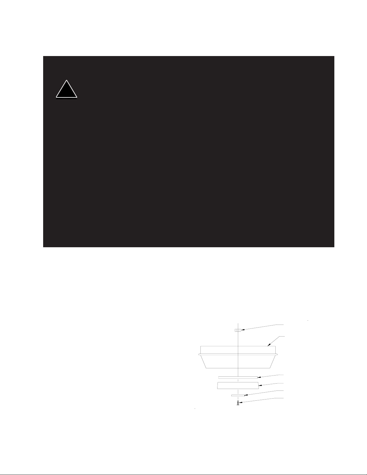
FIGURE 1
Nylock Nut
Base
Gasket
Magnet
Fender Washer
#10-24 x 7/8" Screw
2
Page 3

Larger wires and tight connections will provide longer service life for components. For high current
wires it is highly recommended that terminal blocks or soldered connections be used with shrink tubing to
protect the connections. Do not use insulation displacement connectors (e.g. 3M® Scotchlock type connectors). Route wiring using grommets and sealant when passing through compartment walls. Minimize the
!
WARNING!
number of splices to reduce voltage drop. High ambient temperatures (e.g. under hood) will significantly
reduce the current carrying capacity of wires, fuses, and circuit breakers. Use "SXL" type wire in engine
compartment. All wiring should conform to the minimum wire size and other recommendations of the
manufacturer and be protected from moving parts and hot surfaces. Looms, grommets, cable ties, and
similar installation hardware should be used to anchor and protect all wiring.
Fuses or circuit breakers should be located as close to the power takeoff points as possible and
properly sized to protect the wiring and devices.
Particular attention should be paid to the location and method of making electrical connections and
splices to protect these points from corrosion and loss of conductivity.
Ground terminations should only be made to substantial chassis components, preferably directly to the
vehicle battery.
The user should install a fuse sized to approximately 125% of the maximum Amp capacity in the supply
line to protect against short circuits. For example, a 30 Amp fuse should carry a maximum of 24 Amps. DO
NOT USE 1/4" DIAMETER GLASS FUSES AS THEY ARE NOT SUITABLE FOR CONTINUOUS DUTY IN
SIZES ABOVE 15 AMPS. Circuit breakers are very sensitive to high temperatures and will "false trip" when
mounted in hot environments or operated close to their capacity.
Stanchion Mounting
The 550TM Beacon can be modified for stanchion mounting by purchasing one of the factory available
threaded flanges, 1/2" NPT, 3/4" NPT or 1" NPT kits. A universal pipe flange mounting kit is also available.
Magnetic Mounting
1) Rust Stains: The magnetic mount is not intended as a permanent mounting for the beacon. Long
!
WARNING!
To Operate: Plug Code 3 supplied coil cord into a 12 volt D.C. cigarette lighter; rotate and push firmly to
insure the best possible connection. The beacon should be placed in the center of the roof where the
least amount of curvature takes place. The magnetic beacon should not be used on a vinyl covered roof.
Before installing, check magnet for clinging debris. Any foreign matter can reduce holding power and
scratch the vehicle's paint. The roof surface should be dry and have a dull, not glossy finish. A glossy,
highly waxed finish will reduce the friction and the magnets, though quite powerful, will have a greatly
reduced magnetic effect. Place and remove your beacon without sliding to avoid scratching. When
removing, lift one edge, then the other straight up without sliding.
duration usage of any magnet will expose the high iron content of the steel causing rust. The device should
be removed when not used to prevent rust stains. Metallic debris collected by the magnet will also contribute
to rust stains. Insure that the magnet is kept clean.
2) Surface rust stains can usually be removed with chrome polish, available at most auto part stores.
3) As with any magnetically-mounted warning device, its use on the exterior of a moving vehicle is at
the sole discretion and responsibility of the user.
This magnetic mount product provides a secure, temporary installation in most circumstances and is
recommended for stationary use only. For maximum warning signal, mount the beacon on the highest
possible flat, level surface of the vehicle.
3
Page 4

A Code 3 supplied magnetic mounting kit is available for field retrofit, if required. The lens and rotator
assembly must be removed so that the mounting hole is accessible for drilling. Use a #11 (.191") bit to
drill the mounting hole from inside the base. Drop the nylock nut into place. Assemble washer, screw
and magnet as shown in Figure 1 and attach to base.
Permanent - Resilient Mounting
Locate the Model 550TM Beacon on the highest possible level surface on the vehicle for the maximum
warning signal. CAUTION! When drilling into any vehicle surface, make sure that each side is free from
anything that could be damaged (i.e. electrical wires, fuel lines or vehicle upholstery). Remove the lens
and use the base as a template to mark the wiring and four mounting holes onto the area you wish to
mount the beacon. You must first use a #11 (.191") drill bit and drill out the four mounting holes, see
Figure 2. The two mounting holes closer to the edge of the base may be used when trying to fit an
existing hole pattern. Then, using the base as a template and a 3/8" drill bit, drill wiring and mounting
holes. After drilling the holes, remove any burrs and install a rubber grommet before passing wires
through the wiring hole, apply sealant around wires to seal hole to prevent leakage.
For permanent mounting, use user supplied hardware. For resilient mounting, use a factory available
Resilient Mounting Kit. See Figure 3 for mounting positions. The correctly installed rubber-threaded
insert is a watertight and shock-resistant mount which will increase the effectiveness and long life of the
product. Do not overtighten the screws! In applications where the screws protrude into the passenger
compartment, the screw can be reversed to minimize the risk of personal injury. See Figure 4. In this
configuration do not tighten the nut until all hardware is positioned properly.
Edge
Mounting
Holes
Aux.
Drain / Vent
FIGURE 3
Drain
& Vent
FIGURE 2
#10-32 x 1 1/2" Screw
#10 Screw Washer
Mounting Boss on
Beacon Base
3
/8" Rubber Threaded Insert
3
/8" Dia. Hole
Standard
Mounting
Holes
FIGURE 4
#10-32 Nylock Nut
#10 Screw Washer
Mounting Boss on
Beacon Base
3
/8" Rubber Threaded Insert
#10-32 x 1 1/2" Screw
3
/8" Dia. Hole
4
Page 5

Maintenance
Lens Removal
Remove the 3 mounting screws and lift off the lens.
Lamp Replacement
Incandescent lamps are extremely hot! Allow to cool completely
!
WARNING!
S795 50 WATT LAMP
Grasp lamp with fingers, push down and turn counterclockwise, then remove. Install new lamp by
aligning pins with slots, pushing down and turning clockwise until it stops, then release.
H-1 55 WATT LAMP
First grasp lamp at base and turn until retaining clip is accessible. Using a blade screwdriver, remove
retaining clip and pull lamp straight up. Replace with new lamp. Insure that the power lead and retaining
clip is fully inserted.
NOTE: Do not touch lamp with your bare fingers, as this will damage the lamp and shorten its life. If
touched accidentally, it should be gently wiped off with alcohol and a soft cloth.
before attempting to remove. Gloves and eye protection should be
worn when handling halogen lamps as they are pressurized and
accidental breakage can result in flying glass. High voltages and/or
temperatures are present inside of strobe units. Disconnect from
power and wait 10 minutes prior to servicing.
Reflector Removal
S795 50 WATT REFLECTOR
Slip off the snap ring under the lamp socket and lift off the reflector assembly.
H-1 55 WATT REFLECTOR
Remove lamp as described above and lift off the reflector assembly.
Motor Replacement
Remove reflector as described above. Remove the mounting screws. Cut lamp and motor wires and lift
out the motor, socket and shaft assembly. Install the new assembly and crimp the wires together in their
original location. Test the unit before replacing the lens.
Drainage & Air Exchange
The 550 Beacon is a sealed unit. An air exchange and drainage locating boss has been molded into the
base. The user may drill it out before installation. Drill out the drain/vent hole with a #11 (.191") drill bit as
shown in Figure 2.
General
Do not oil or grease the unit. It is constructed with permanently lubricated bearings and plastic gears
which are factory lubricated. Keep the unit clean by disassembling it and cleaning bearing surfaces with
mineral spirits (turpentine), and clear any debris out of the drive gears. Clean lens and base with soap
and water, or CODE 3 lens polish using a soft cloth.
5
Page 6

Parts List
Ref No. Description Part No. Qty.
1 Lens - Green T02300 1
- Clear T02301
- Red T02302
- Blue T02303
- Amber T02304
- DIN Blue T02305
2 Reflector Assembly S96820 1
3 50 Watt halogen lamp T01540 1
4 Wire washer assembly T05028 1
5 Lamp spring T04936 1
6 Motor plate mounting screws T00243 2
7 Standard motor plate assembly S96814 1
8 Lens retaining screw T01647 3
9 Plastic base T09934 1
H-1 Parts Not Shown:
Terminated lamp wire T00940
H-1 55 Watt lamp T01543
Reflector assembly S96820
Lamp retaining clip T04933
Options Not Shown:
Resilient mount kit T01849
Magnetic Mounting Kit S85143
Magnetic mount - coil cord assembly S23011
Magnets T00499
Magnet gaskets T01119
Fender Washer T00142
#10-24 x 7/8" Screw T05520
#10-24 Nylock Nut T05501
Drain hole plug T01237
Stanchion mount kits
- 1" NPT Pipe flange mounting kit 3F1(H)
- 1/2" NPT Pipe flange mounting kit 3F2(H)
- 3/4" NPT Pipe flange mounting kit 3F3(H)
- Universal Pipe flange mounting kit 3U(H)
Shock Mount Option 50W
550 S13515 STD.
550H S13518 FAST
Fast Motor Plate Assy.
- Bayonet S96835
6
Page 7

1
2
3
4
5
6
7
8
9
FIGURE 5
7
Page 8

WARRANTY
Code 3, Inc.'s emergency devices are tested and found to be operational at the time of
manufacture. Provided they are installed and operated in accordance with manufacturer's
recommendations, Code 3, Inc. guarantees all parts and components except the lamps to a period
of 1 year (unless otherwise expressed) from the date of purchase or delivery, whichever is later.
Units demonstrated to be defective within the warranty period will be repaired or replaced at the
factory service center at no cost.
Use of lamp or other electrical load of a wattage higher than installed or recommended by the
factory, or use of inappropriate or inadequate wiring or circuit protection causes this warranty to
become void. Failure or destruction of the product resulting from abuse or unusual use and/or
accidents is not covered by this warranty. Code 3, Inc. shall in no way be liable for other damages
including consequential, indirect or special damages whether loss is due to negligence or breach
of warranty.
CODE 3, INC. MAKES NO OTHER EXPRESS OR IMPLIED WARRANTY INCLUDING,
WITHOUT LIMITATION, WARRANTIES OF FITNESS OR MERCHANTABILITY, WITH
RESPECT TO THIS PRODUCT.
PRODUCT RETURNS
If a product must be returned for repair or replacement*, please contact our factory to
obtain a Return Goods Authorization Number (RGA number) before you ship the product to
Code 3, Inc. Write the RGA number clearly on the package near the mailing label. Be sure you
use sufficient packing materials to avoid damage to the product being returned while in transit.
*Code 3, Inc. reserves the right to repair or replace at its discretion. Code 3, Inc. assumes no responsibility or liability for expenses incurred for
the removal and /or reinstallation of products requiring service and/or repair.; nor for the packaging, handling, and shipping: nor for the handling of
products return to sender after the service has been rendered.
NEED HELP? Call our Technical Assistance Hotline - (314) 996-2800
550 is a trademark and Code 3 is a registered trademark fo Code 3, Inc. a subsidiary of Public Safety Equipment, Inc.
St. Louis, Missouri 63114-2029—USA
Revision 7, 01/2006 - Instruction Book Part No. T09034
10986 N. Warson Road
www.code3pse.com
©2001-6 Code 3, Inc. Printed in USA
Code 3, Inc.
 Loading...