

Page 1

INST ALLA TION
&OPERATION
MANUAL
MODEL
310
TM
MODEL 310
TM
SINGLE LAMP REVOL VING BEACON
Contents:
Introduction (with warnings) ............................... 2
Unpacking & Pre-Installation .............................. 2
Wiring Instructions .............................................. 2
Mounting Instructions/Warnings ......................... 3
Maintenance.........................................................4
Parts List (Replacement Parts/Exploded View)... 5
Warranty.............................................................. 6
Read all instructions and warnings before installing and using.Read all instructions and warnings before installing and using.
Read all instructions and warnings before installing and using.
IMPORTANT:
Read all instructions and warnings before installing and using.Read all instructions and warnings before installing and using.
INSTALLER: INSTALLER:
INSTALLER:
INSTALLER: INSTALLER:
This manual must be delivered to the end user of this equipment. This manual must be delivered to the end user of this equipment.
This manual must be delivered to the end user of this equipment.
This manual must be delivered to the end user of this equipment. This manual must be delivered to the end user of this equipment.
Page 2

Introduction
The 310TM beacon has a single rotating warning signal which exceeds, by several times, the SAE standards set
for rotating warning lights, and is available in permanent, magnetic, or stanchion mount configurations.
The use of this or any warning device does not insure that all drivers can or will observe or
react to an emergency warning signal. Never take the right-of-way for granted. It is your
responsibility to be sure you can proceed safely before entering an intersection, driving
against traffic, responding at a high rate of speed, or walking on or around traffic lanes.
!
WARNING!
The effectiveness of this warning device is highly dependent upon correct mounting and
wiring. Read and follow the manufacturer’s instructions before installing or using this
device. The vehicle operator should insure daily that all features of the device operate
correctly. In use, the vehicle operator should insure the projection of the warning signal
is not blocked by vehicle components (i.e.: open trunks or compartment doors), people,
vehicles, or other obstructions.
This equipment is intended for use by authorized personnel only. It is the user’s responsibility to understand and obey all laws regarding emergency warning devices. The user
should check all applicable city, state and federal laws and regulations.
Code 3, Inc., assumes no liability for any loss resulting from the use of this warning
device.
Proper installation is vital to the performance of this warning device and the safe operation of the emergency vehicle. It is important to recognize that the operator of the emergency vehicle is under psychological and physiological stress caused by the emergency
situation. The warning device should be installed in such a manner as to: A) Not reduce
the output performance of the system, B) Place the controls within convenient reach of
the operator so that he can operate the system without losing eye contact with the
roadway.
Emergency warning devices often require high electrical voltages and/or currents. Properly protect and use caution around live electrical connections. Grounding or shorting of
electrical connections can cause high current arcing, which can cause personal injury
and/or severe vehicle damage, including fire.
PROPER INSTALLATION COMBINED WITH OPERATOR TRAINING IN THE PROPER
USE OF EMERGENCY WARNING DEVICES IS ESSENTIAL TO INSURE THE SAFETY
OF EMERGENCY PERSONNEL AND THE PUBLIC.
Unpacking & Pre-installation
Carefully remove the beacon and place it on a flat surface, taking care not to scratch the lens. Examine the
unit for transit damage, broken lamps, etc. If it is convenient, you may wish to test the unit before installation.
To test, touch the black wire to the negative ground (earth) and the red wire to the +12 VDC. A battery charger
may be used for this purpose. If the vehicle has an electrical system other than 12 VDC. negative ground
(earth), and you have not ordered a specially wired beacon, contact your local representative or call the factory
for instructions.
Installation & Mounting
Wiring Instructions
The Model 310 Beacon is designed to operate on a 12 VDC negative ground (earth) system. Using #14 ga. or
larger wires, connect the black lead to vehicle chassis (earth), or preferably the negative (earth) terminal of the
battery. Bring the red lead to the user supplied control switch, and then to the battery or to the stud on the
battery side of the starter solenoid or alternator. Install a fuse or circuit breaker of 10 amp capacity in the
supply line to protect the vehicle’s wiring system against short circuits.
2
Page 3
Magnetic Mounting
1) Rust Stains: The magnetic mount is not intended as a permanent mounting for the
beacon. Long duration usage of any magnet will expose the high iron content of the steel
!
WARNING!
causing rust. The device should be removed when not used to prevent rust stains. Metallic
debris collected by the magnet will also contribute to rust stains. Insure that the magnet is
kept clean.
2) Surface rust stains can usually be removed with chrome polish, available at most auto
part stores.
3) As with any magnetically-mounted warning device, its use on the exterior of a moving
vehicle is at the sole discretion and responsibility of the user.
This magnetic mount product provides a secure, temporary installation in most circumstances and is recommended for stationary use only. For maximum warning signal, mount
the beacon on the highest possible flat, level surface of the vehicle.
Stanchion Mounting
The 310TM Beacon is available with factory installed threaded flanges, 1/2” NPT or 3/4” NPT. Route the wiring as
described above and make the recommended connections. Guide user wiring through the pipe and terminate
securely to the power lead and ground wires of the Mode 310 Beacon. Fasten the flange mount beacon onto the
pipe by hand until secure. DO NOT OVERTIGHTEN!
Permanent-Resilient Mounting
Locate the Model 310 Beacon on the highest possible level surface on the vehicle for the maximum warning
signal. Caution! When drilling into any vehicle surface, make sure that each side is free from anything that
could be damaged (i.e., electrical wires, fuel lines or vehicle upholstery). Use the three mounting bosses of the
beacon base as a template to establish pilot holes. Drill three equally spaced 3/8” holes on a 5-1/2” dia. bolt
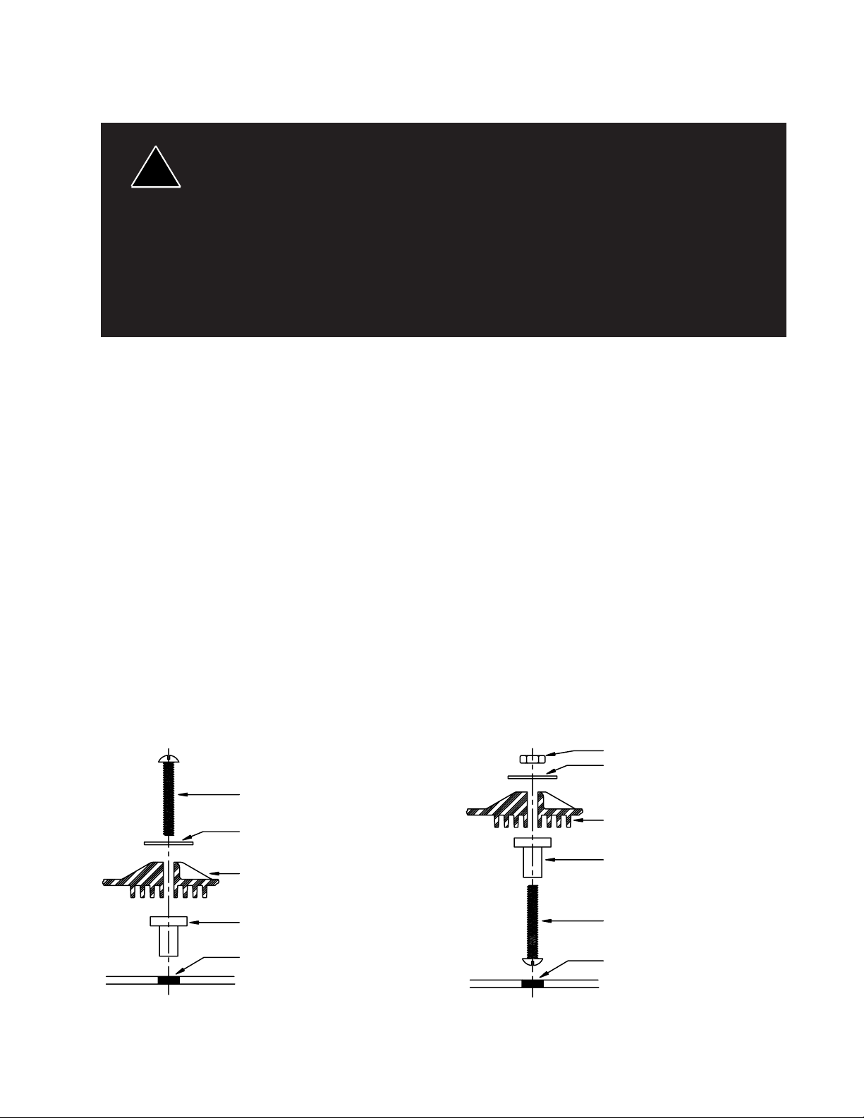
circle. See Figure 1. Locate the mounting hardware as illustrated and insert into the 3/8” holes. The correctly
installed rubber-threaded insert is a watertight and shock-resistant mount which will increase the effectiveness
and long life of the product. Do not overtighten the screws! In applications where the protruding screw enters
the passenger compartment, the screw can be reversed to minimize the risk of personal injury on the protruding
screw threads. See figure 2. Do not tighten nut until hardware is positioned properly .
#10-32 Nut (User Supplied)
1" Dia. Flat Washer
#10-32 x 1 1/2" Screw
1" Dia. Flat Washer
Mounting Boss on
Beacon Base
3/8" Rubber
Threaded Insert
3/8" Dia. Hole on
5 1/2" Dia. Bolt Circle
Mounting Boss on
Beacon Base
3/8" Rubber
Threaded Insert
#10-32 x 1 1/2" Screw
3/8" Dia. Hole on
5 1/2" Dia. Bolt Circle
FIGURE 1
FIGURE 2
3
Page 4

Maintenance
Lamps are extremely hot! Allow to cool completely before attempting to remove. Gloves
!
WARNING!
and eye protection should be worn when handling halogen lamps as they are pressurized
and accidental breakage can result in flying glass.
Lens Removal
Remove the 4 mounting screws and lift off the lens.
Lamp Replacement
H-1 55 WATT LAMP
First grasp lamp at base and turn until retaining clip is accessible. Using a blade screwdriver, remove retaining
clip and pull lamp straight up. Replace with new lamp. Insure that the power lead and retaining clip is fully
inserted.
NOTE: Do not touch new lamp with your bare fingers, as this will damage the lamp and shorten its life. If
touched accidentally, it should be gently wiped off with alcohol and a soft cloth.
Reflector Removal
H-1 55 WATT REFLECTOR
Remove lamp as described above and lift off the reflector assembly.
Motor Replacement
Remove reflector as described above. Remove the two motorplate mounting screws. Cut lamp wire and lift
out motor, socket and shaft assembly. Install new assembly and solder the wires to their original location.
Test unit before replacing the lens.
General
Do not oil or grease this unit. Doing so voids the product warranty. It is constructed with permanently
lubricated bearings and plastic gears which do not need lubrication. Keep the unit clean by disassembling it
and cleaning bearing surfaces with mineral spirits (turpentine), and clear any debris out of the drive gears.
Clean lens and base with soap and water, using soft cloth or paper towel. In severe climates excessive
condensation may occur - if so, drill open the two remaining auxiliary ventilation holes.
4
Page 5

Parts & Exploded Views
( See exploded diagram)
1
10
7
3
4
5
6
8
9
1211
2
FIGURE 3
Parts List
Ref No. Description Part No. Qty.
1 Lens - Amber 2224 1
- Red 2222
- Blue 2223
- Green 2220
2 Reflector Assembly S03069 1
3 Retaining Clip 928 1
4 Power Wire Assembly S91431 1
5 H1 Motorplate Assembly S91330 1
6 Rotator Mounting Bracket S70361 1
7 55 Watt H1 halogen lamp 1543 1
8 Lens Retaining Screws 1647 4
9 Base Assembly S70362 1
10 #10-32 x 1 1/2 Screw 6929 3
11 1 Dia. Gasket (Magnetic Mount only) 1642 3
12 #10-32 Nut 5501 3
Parts Not Shown
16 Fastener Parts Bag 1849
17 Coil Cord with Lighter Plug 502
18 1" NPT Pipe Flange Mounting Kit 3F1H
19 1/2" NPT Pipe Flange Mounting Kit 3F2H
20 3/4" NPT Pipe Flange Mounting Kit 3F3H
21 Universal Pipe Flange Mounting Kit 3UH
22 Magnets 1587
NOTE: Removal of reflector assembly from gear/shaft/plate assembly is not necessary for partial
disassembly of unit or general maintenance.
5
Page 6

NOTES
6
Page 7

NOTES
7
Page 8

WARRANTY
Public Safety Equipment emergency devices are tested and found to be operational at the time
of manufacture. Provided they are installed and operated in accordance with manufacturer's
recommendations, PSE guarantees all parts and components except the lamps to a period of 1 year
(unless otherwise expressed) from the date of purchase or delivery, whichever is later. Units
demonstrated to be defective within the warranty period will be repaired or replaced at the factory
service center at no cost.
Use of lamp or other electrical load of a wattage higher than installed or recommended by
the factory, or use of inappropriate or inadequate wiring or circuit protection causes this warranty
to become void. Failure or destruction of the product resulting from abuse or unusual use and/
or accidents is not covered by this warranty. PSE shall in no way be liable for other damages
including consequential, indirect or special damages whether loss is due to negligence or breach of
warranty.
Public Safety Equipment, INC. MAKES NO OTHER EXPRESS OR IMPLIED WARRANTY INCLUDING, WITHOUT LIMITATION, WARRANTIES OF FITNESS OR MERCHANTABILITY, WITH RESPECT TO THIS PRODUCT.
PRODUCT RETURNS
If a product must be returned for repair or replacement*, please contact our factory to obtain a Return
Goods Authorization Number (RGA number) before you ship the product to Public Safety Equipment, Inc.
Write the RGA number clearly on the package near the mailing label. Be sure you use sufficient packing
materials to avoid damage to the product being returned while in transit.
*Public Safety Equipment, Inc. reserves the right to repair or replace at its discretion and assumes no responsibility
or liability for expenses incurred for the removal or reinstallation of products requiring service or repair.; nor for the
packaging, handling, and shipping: nor for the handling of products return to sender after the service has been rendered.
Trouble Shooting Guidelines
If you experience any product problems, please refer to the Troubleshooting Guidelines located in most
Operation and Installation Manuals. If you need further assistance, please call our Technical Help Hotline @
(314)426-2700, ext. 2131 or 2132. We will be happy to assist you.
PROBLEMS OR QUESTIONS? CALL OUR TECHNICAL ASSIST ANCE HOTLINE (314) 996-2800
www.CODE3PSE.COM
Ph. (314) 426-2700 Fax (314) 426-1337
310 and PSE AMBER are trademarks of Public Safety Equipment, Inc.
Public Safety Equipment, Inc.
St. Louis, Missouri 63114-2029—USA
Revision 4, 3/2008 - Instruction Book Part No. T07843
©2008 Public Safety Equipment, Inc. Printed in USA
10986 N. Warson Road
 Loading...