

Page 1
INSTALLATION
& OPERATION
MANUAL
275/275AH/275ASH/
275AMH BEACON
275 Beacon
12v MODELS
PERMANENT, MAGNETIC MOUNT
BEACONS
Contents:
Introduction ........................................................ 2
Unpacking & Pre-Installation .............................. 2
Installation & Mounting ....................................... 2
Magnetic Mounting ........................................... 3
Permanent Mounting ........................................ 3
Wiring Instructions ............................................ 5
Maintenance ....................................................... 6
Drill Template............................................................ 7
Warranty ............................................................. 8
IMPORTANT:
Read all instructions and warnings before installing and using.
INSTALLER: This manual must be delivered to the end user of this equipment.
Page 2

Introduction
The 275 Beacon has a sleek, aerodynamtic profile and is a powerful mid-sized, magnetically or permanently
mounted warning device. This product complies with SAE W3-1 97, EMC Directives 95/54/EC and 89/336/EC
The use of this or any warning device does not insure that all drivers can or will observe or
react to an emergency warning signal. Never take the right-of-way for granted. It is your
responsibility to be sure you can proceed safely before entering an intersection, driving
!
WARNING!
against traffic, responding at a high rate of speed, or walking on or around traffic lanes.
The effectiveness of this warning device is highly dependent upon correct mounting and
wiring. Read and follow the manufacturer’s instructions before installing or using this
device. The vehicle operator should insure daily that all features of the device operate
correctly. In use, the vehicle operator should insure the projection of the warning signal is
not blocked by vehicle components (i.e.: open trunks or compartment doors), people,
vehicles, or other obstructions.
This equipment is intended for use by authorized personnel only. It is the user’s responsibility to understand and obey all laws regarding emergency warning devices. The user
should check all applicable city, state and federal laws and regulations.
Code 3, Inc., assumes no liability for any loss resulting from the use of this warning device.
Proper installation is vital to the performance of this warning device and the safe operation
of the emergency vehicle. It is important to recognize that the operator of the emergency
vehicle is under psychological and physiological stress caused by the emergency situation.
The warning device should be installed in such a manner as to: A) Not reduce the output
performance of the system, B) Place the controls within convenient reach of the operator
so that he can operate the system without losing eye contact with the roadway.
Emergency warning devices often require high electrical voltages and/or currents. Properly
protect and use caution around live electrical connections. Grounding or shorting of
electrical connections can cause high current arcing, which can cause personal injury and/
or severe vehicle damage, including fire.
PROPER INSTALLATION COMBINED WITH OPERATOR TRAINING IN THE PROPER
USE OF EMERGENCY WARNING DEVICES IS ESSENTIAL TO INSURE THE SAFETY
OF EMERGENCY PERSONNEL AND THE PUBLIC.
Unpacking & Pre-installation
Carefully remove the beacon and place it on a flat surface, taking care not to scratch the lens. Examine the
unit for transit damage, broken lamps, etc.
If it is convenient, you may wish to test the unit before installation. To test, touch the black wire to the
negative ground (earth) and the red wire to the +12 Volts D.C. A battery may be used for this purpose. If the
vehicle has an electrical system other than 12 Volts D.C. negative ground (earth), and you have not ordered a
specially wired beacon, contact your local representative or call the factory for instructions.
Installation & Mounting
The 275 Beacon may be mounted magnetically or permanently on the roof of the vehicle, or other mounting
surface.
Overall Size : 5.938 Dia. X 5.775 Tall. Magnetic Mount Models.
6.125 Dia. X 6.125 Tall.
General
All devices should be mounted in accordance with the manufacturer's instructions and securely fastened to
vehicle elements of sufficient strength to withstand the forces applied to the device. Driver and/or passenger
air bags (SRS) will affect the way equipment should be mounted. This device should be mounted by permanent installation and within the zones specified by the vehicle manufacturer, if any. Any device mounted in the
deployment area of an air bag will damage or reduce the effectiveness of the air bag and may damage or
dislodge the device. Installer must be sure that this device, its mounting hardware and electrical supply wiring
does not interfere with the air bag or the SRS wiring or sensors. Front or rear grille/bumper placement must
avoid interference with SRS sensors. Mounting the unit inside the vehicle by a method other than permanent
installation is not recommended as unit may become dislodged during swerving, sudden braking or collision.
Failure to follow instructions can result in personal injury.
2
Page 3
Magnetic Mounting
1) Rust Stains: The magnetic mount is not intended as a permanent mounting for the
beacon. Long duration usage of any magnet will expose the high iron content of the steel
causing rust. The device should be removed when not used to prevent rust stains. Metal-
!
WARNING!
The 275 Magnetic Based Beacon provides a secure, temporary installation in most circumstances. The
beacon should be placed in the center of the roof where the least amount of curvature occurs. The
beacon should not be used on a vinyl covered roof. Before installing, check the magnet for clinging
debris. Any foreign matter can reduce holding power and scratch your vehicle's paint. The roof surface
should be dry and have a dull, not glossy finish. A glossy, highly waxed finish will reduce the friction; and
the magnet, though quite powerful, will have a greatly reduced effect. Place and remove your beacon
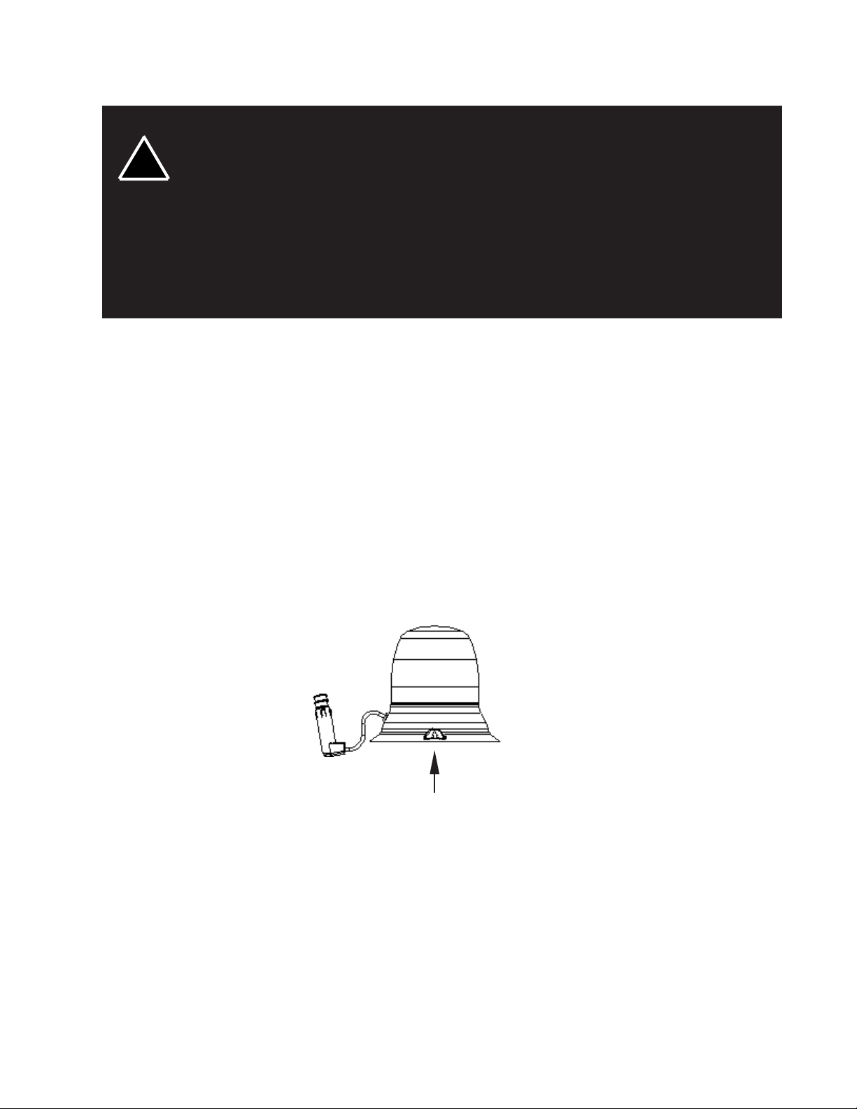
without sliding to avoid scratching. When removing, lift one edge straight up without sliding. The suction/
magnetic mount has a tab to release the suction, refer to Figure 1.
lic debris collected by the magnet will also contribute to rust stains. Insure that the magnet
is kept clean.
2) Surface rust stains can usually be removed with chrome polish, available at most auto
part stores.
3) As with any magnetically-mounted warning device, its use on the exterior of a moving
vehicle is at the sole discretion and responsibility of the user.
This magnetic mount product provides a secure, temporary installation in most circumstances and is recommended for stationary use only. For maximum warning signal, mount
the beacon on the highest possible flat, level surface of the vehicle.
When the beacon is placed on the roof, it should adhere firmly to the surface. If the unit slides or moves
easily, a proper installation has not been obtained, most probably for one of the reasons mentioned above.
In this situation, the user should not attempt to drive with the beacon in place. If the user has attempted
to obtain a good installation and still has questions, we recommend that the user (customer) contact his/
her distributor or the factory.
Do not install the beacon closer than 20" to any antenna or aerial.
FIGURE 1
LIFT UP TO RELEASE
Permanent Mounting
The 275 Permanent Mount Beacon provides a secure, permanent installation. To begin installation,
consider where the wire routing will be located. Electrical cables can affect other equipment! Route product
supply cables away from sensitive cables (e.g. radio, aerials and anti-lock braking systems etc.) If this is
not possible, cross the cables at 90 Deg. Using the enclosed template, refer to Figure 5 on page 7, mark
the centers for mounting holes on the vehicle roof or mounting surface. Drills can be dangerous! Make
sure the person operating the drill is trained and takes adequate safety precautions. Drill a .250" hole
through all 3 centers, a .500" hole at the center and remove any burrs. Place the supplied mounting
gasket in position, refer to Figure 2. Run, the supplied M6 machine screws through the drilled holes (For
thicker surfaces use longer screws). Place one nut, with lock washer, onto each screw and tighten screws
until base is properly secured to mounting surface. Number 8 self-tapping sheet metal screws (user
supplied) may be substituted for the bolts and threaded into the bosses molded in the base.
3
Page 4

SUPPLIED MOUNTING GASKET
TIGHTENING TORQUE: 5 lb-in
DRAIN SLOT TOWARD REAR OF VEHICLE
LIGHT BASE
BOLT M6
VEHICLE PANEL
SPRING WASHER
NUT M6
18-16 GA WIRE
(WIRE NOT SUPPLIED)
.187in FEMALE
CONNECTOR (-)
.250in FEMALE
CONNECTOR (+)
FIGURE 2
4
Page 5

Wiring Instructions
Larger wires and tight connections will provide longer service life for components. For high
current wires it is highly recommended that terminal blocks or soldered connections be
used with shrink tubing to protect the connections. Do not use insulation displacement
connectors (e.g. 3M® Scotchlock type connectors). Route wiring using grommets and
sealant when passing through compartment walls. Minimize the number of splices to
reduce voltage drop. High ambient temperatures (e.g. under-hood) will significantly reduce
!
WARNING!
the current carrying capacity of wires, fuses, and circuit breakers. Use "SXL" type wire in
engine compartment. All wiring should conform to the minimum wire size and other
recommendations of the manufacturer and be protected from moving parts and hot
surfaces. Looms, grommets, cable ties, and similar installation hardware should be used to
anchor and protect all wiring.
Fuses or circuit breakers should be located as close to the power takeoff points as possible
and properly sized to protect the wiring and devices.
Particular attention should be paid to the location and method of making electrical
connections and splices to protect these points from corrosion and loss of conductivity.
Ground terminations should only be made to substantial chassis components, preferably
directly to the vehicle battery.
The user should install a fuse sized to approximately 125% of the maximum Amp capacity
in the supply line to protect against short circuits. For example, a 30 Amp fuse should
carry a maximum of 24 Amps. DO NOT USE 1/4" DIAMETER GLASS FUSES AS THEY
ARE NOT SUITABLE FOR CONTINUOUS DUTY IN SIZES ABOVE 15 AMPS. Circuit
breakers are very sensitive to high temperatures and will "false trip" when mounted in hot
environments or operated close to their capacity.
275 Magnetic Mount Beacon - The 275 Beacon can be equipped with a cord that plugs into a 12 Volt
D.C. cigarette lighter; rotate and push with reasonable moderate force which insures the best possible
connection.
275 Permanent Mount Beacon - The 275 beacon is designed to operate on a 12 Volt D.C. negative
ground (earth) system. Use #18 GA. or larger wires. Connect black lead to vehicle chassis (earth),
or preferably the negative (earth) terminal of the battery. Bring the red lead to the user supplied
control switch, and then to the battery or to the stud on the battery side of the starter solenoid or
alternator. Install a fuse or circuit breaker of 8 Amp capacity in the supply line to protect the vehicle's
wiring system against short circuits.
LENS P/N COLOR
T07982
T07983
T07984
RED
BLUE
AMBER
ANTI-THEFT SCREW
LENS OPENING AND CLOSING
5
Page 6

WARNING: RATED VOLTAGE IS INDICATED ON THE BACK OF REFLECTOR
BULB P/N
T01543
12v APPLICATIONS ONLY
FIGURE 4
DO NOT TOUCH GLASS PORTION
OF LAMP
Maintenance
Do not oil or grease this unit. It is constructed with permanently lubricated bearings which do not need
lubrication. Keep the unit clean by disassembling it and clearing any debris or dirt. Clean lens and base
with mild soap and water, or CODE 3® lens polish using a soft cloth. The lens may be removed, and the
lamps replaced as shown in Figure 4. Use only lamps with the same rated wattage and voltage.
Lamps are extremely hot! Allow to cool completely before attempting to remove. Gloves
!
WARNING!
Use no SOLVENTS on lens.
Failure to follow above warnings or installation and user instructions can result in loss of warranty coverage.
and eye protection should be worn when handling halogen lamps as they are pressurized and
accidental breakage can result in flying glass.
6
Page 7

Drill Template
5.125
.400
120.0°120.0°
3X .250
FIGURE 5
NOT TO SCALE
7
Page 8

WARRANTY
Code 3, Inc.'s emergency devices are tested and found to be operational at the time of
manufacture. Provided they are installed and operated in accordance with manufacturer's
recommendations, Code 3, Inc. guarantees all parts and components except the lamps to a period
of 1 year (unless otherwise expressed) from the date of purchase or delivery, whichever is later.
Units demonstrated to be defective within the warranty period will be repaired or replaced at the
factory service center at no cost.
Use of lamp or other electrical load of a wattage higher than installed or recommended by
the factory, or use of inappropriate or inadequate wiring or circuit protection causes this warranty
to become void. Failure or destruction of the product resulting from abuse or unusual use and/
or accidents is not covered by this warranty. Code 3, Inc. shall in no way be liable for other
damages including consequential, indirect or special damages whether loss is due to negligence
or breach of warranty.
CODE 3, INC. MAKES NO OTHER EXPRESS OR IMPLIED WARRANTY INCLUDING, WITHOUT LIMITATION, WARRANTIES OF FITNESS OR MERCHANTABILITY,
WITH RESPECT TO THIS PRODUCT.
PRODUCT RETURNS
If a product must be returned for repair or replacement*, please contact our factory to
obtain a Return Goods Authorization Number (RGA number) before you ship the product to
Code 3, Inc. Write the RGA number clearly on the package near the mailing label. Be sure you
use sufficient packing materials to avoid damage to the product being returned while in transit.
*Code 3, Inc. reserves the right to repair or replace at its discretion. Code 3, Inc. assumes no responsibility or liability for expenses incurred
for the removal and /or reinstallation of products requiring service and/or repair.; nor for the packaging, handling, and shipping: nor for the handling of
products return to sender after the service has been rendered.
Code 3 is a registered trademarks of
Public Safety Equipment, Inc.
Public Safety Equipment, Inc.
St. Louis, Missouri 63114-2029—USA
Ph. (314) 426-2700 Fax (314) 426-1337
Revision 1 5/03 - Instruction Book Part No. T07948
©2002 Public Safety Equipment, Inc. Printed in USA
10986 N. Warson Road
www.code3pse.com
Code 3,® Inc., a subsidiary of
Public Safety Equipment, Inc.
 Loading...