

Page 1

INSTALLATION
& OPERATION
MANUAL
235H
REMOTE STROBE
POWER SUPPLY
TM
235H
IMPORTANT:
REMOTE STROBE
POWER SUPPLY
Contents:
Introduction ......................................................... 2
Standard Features .............................................. 2
Specifications...................................................... 2
Unpackaging & Pre-installation .......................... 3
Installation & Mounting ....................................... 4
Wiring Instructions ........................................... 4-6
Switching Control Variations .............................. 7
Maintenance ....................................................... 8
Troubleshooting .................................................. 8
Internal Fuse Replacement ............................... 9
Warranty .......................................................... 10
Read all instructions and warnings before installing and using.
INSTALLER:
This manual must be delivered to the end user of this equipment.
Page 2

Introduction
The 235H Series Remote Strobe Power Supply represents the latest in state-of-the-art strobe warning
technology. The latest in MOSFET technology and microprocesser control provide efficient and reliable
operation. The model 235H is versitile and economical strobe power supply providing two alternating strobe
outlets. When connected to
accessories the 235H delivers an outstanding level of vehicle warning signals.
CODE 3
®
line of oval and round remote strobe heads, remote 360 beacon, and
Standard Features
All MODEL 235H two-head Remote Strobe Power Supplies come equipped with the following standard
features:
(See Figure 3, page 5)
MULTIPLE OPERATING VOLTAGES
10-30 VDC operation only. Reverse polarity protected
INTERNAL FUSE PROTECTION
User replaceable 7.5 AMP, ATO style fuse.
OUTPUT SHORT CIRCUIT/FLASHTUBE FAILURE PROTECTION
Power supply will shut-off when trying to flash any heads that have been shorted, or have a failed flash tube.
MULTIPLE USER SELECTABLE FLASH PATTERNS
User may select either Double Flash or Quad Flash.
HI/LO POWER CONTROL
Allows reduction of strobe light intensity for night time use. The Lo power control is +VDC switched.
Specifications
OPERATING VOLTAGE: 10-30 VDC
OUTPUT POWER: 35 WATTS NOMINAL
STANDARD FLASH RATE: EACH STROBE LIGHT OUTLET 60 QUAD FLASHES/MIN.
POWER CONSUMPTION: 3.5 AMPS AVERAGE AT 12.8 VDC (HIGH POWER)
1.75 AMPS AVERAGE AT 25.6 VDC (HIGH POWER)
2
Page 3

!
WARNING!
The use of this or any warning device does not insure that all drivers can or will observe or
react to an emergency warning signal. Never take the right-of-way for granted. It is your
responsibility to be sure you can proceed safely before entering an intersection, driving
against traffic, responding at a high rate of speed, or walking on or around traffic lanes.
The effectiveness of this warning device is highly dependent upon correct mounting and
wiring. Read and follow the manufacturer’s instructions before installing or using this
device. The vehicle operator should insure daily that all features of the device operate
correctly. In use, the vehicle operator should insure the projection of the warning signal is
not blocked by vehicle components (i.e.: open trunks or compartment doors), people,
vehicles, or other obstructions.
This equipment is intended for use by authorized personnel only. It is the user’s responsibility to understand and obey all laws regarding emergency warning devices. The user
should check all applicable city, state and federal laws and regulations.
Public Safety Equipment, Inc., assumes no liability for any loss resulting from the use of
this warning device.
Proper installation is vital to the performance of this warning device and the safe operation
of the emergency vehicle. It is important to recognize that the operator of the emergency
vehicle is under psychological and physiological stress caused by the emergency situation.
The warning device should be installed in such a manner as to: A) Not reduce the output
performance of the system, B) Place the controls within convenient reach of the operator
so that he can operate the system without losing eye contact with the roadway.
Emergency warning devices often require high electrical voltages and/or currents. Properly
protect and use caution around live electrical connections. Grounding or shorting of
electrical connections can cause high current arcing, which can cause personal injury and/
or severe vehicle damage, including fire. Do not touch the strobe light tubes, the strobe
light head assemblies or the strobe power supply while the system is in operation. Wait 5
minutes after turning off the power from system before touching any internal componentry.
PROPER INSTALLATION COMBINED WITH OPERATOR TRAINING IN THE PROPER
USE OF EMERGENCY WARNING DEVICES IS ESSENTIAL TO INSURE THE SAFETY
OF EMERGENCY PERSONNEL AND THE PUBLIC.
Unpacking and Pre-Installation
Remove the power supply from the box and examine the unit for any transit damage. Report any damage to
the carrier immediately. Inspect the supplied user parts kit , this should contain:
A. 1 POWER INPUT/CONTROL HARNESS ASSEMBLY consisting of one AMP 4 pin connector with
four wires, Red power wire positive (+12/24VDC), Black wire negative (Ground/Earth),Orange
(Quad Flash Selection) and Green wire (Hi/Lo intensity). This assembly is to be connected to
customer supplied power harness and control switching.
B. TWO AMP 3-PIN PLUG HOUSINGS to be connected to the remote strobe light head cables.
(See Installation and Mounting section).
C. FOUR #8 SHEET METAL SCREWS for mounting the power supply.
3
Page 4
Installation and Mounting
MOUNTING THE MODEL 235H REMOTE STROBE POWER SUPPLY
To obtain maximum performance and durability the Model 235H should be mounted as follows:
1. Mount the unit with the strobe light outlets located in such a way that they are easily accessible.
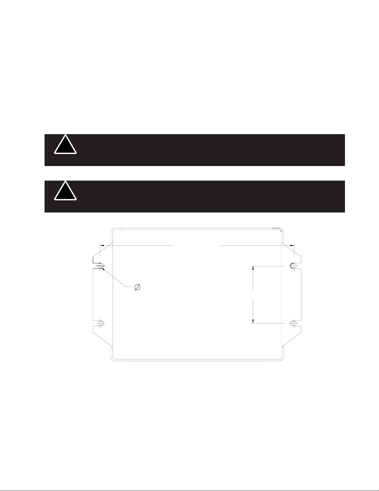
2. Mount the unit with the four supplied #8 sheet metal screws. If possible, a metal surface should be chosen
for best heat dissipation. The mounting hole pattern dimensions are shown in Figure 1. The power supply
can be used as a template, if desired, to mark the drill locations. Predrill this surface with a 9/64 drill and
secure the unit.
!
WARNING!
!
WARNING!
The Model 235H Strobe Power Supply is NOT waterproof and should be located in an area
protected from the weather and water.
High voltages and/or temperatures are present inside the unit. Disconnect from power and
wait 5 minutes prior to servicing or troubleshooting. Use hand and eye protection when
changing halogen lamps or flashtubes.
7.00
.141
2.00
FIGURE 1
WIRING
STROBE LIGHT HEAD CABLE CONNECTIONS
1. Install the remote strobe light heads in the desired locations and route the three wire cable from the remote
heads to the 235H power supply. Leave enough cable at the power supply so that the cables are not
strained when connected to the power supply. Follow all installation instructions supplied with the remote
strobe light heads to determine how the cables connect to the strobe heads. PSE offers a variety of strobe
light head options that can be powered by the 235H.
4
Page 5

2. After the cables have been properly routed for each strobe head they will have to be terminated with the
three pin AMP socket housings provided. The cables are factory terminated with the proper AMP crimp
pins for insertion into the housings, see Figure 2. If there is a need to re-terminate any wires, Figure 2 also
includes stripping and crimping information.
NOTE: USE AMP HAND TOOL PART NO. 90124-2 OR EQUIVALENT TO CRIMP SOCKET PINS TO THE
WIRES.
CRIMP TO INSULATION ONLY
CRIMP OVER BARE WIRE
STRIP INSULATION TO EXPOSE
BARE WIRE AS SHOWN
THIS END TO POWER
SUPPLY
AMP 3 PIN SOCKET HOUSING
PN 1-480303-0
AMP SOCKET PIN
PN 60619-9
It is very important to observe the pin locations and color on the AMP three pin socket
housings. Improper connections could damage the remote strobe heads, see Figure 3.
WARNING!
1/8 INCH
WHITE WIRE - (TRIGGER) POSITION 3
BLACK WIRE - (CATHODE) POSITION 2
RED WIRE - (ANODE) POSITION 1
FIGURE 2
!
Alternating
Outlets
Power-In/
Control
Strobe Light Heads
Power-In/Control
Harness
FIGURE 3
5
Page 6

3. With the AMP 3 pin connectors terminated properly , plug each cable into the appropriate 3 position socket
on the 235H strobe power supply, see Figure 3, page 5.
POWER-INPUT WIRE HARNESS ASSEMBLY
The Power-input/Control harness is to be connected to the 4-position socket connector on the 235H strobe
power supply. See Figure 3, page 5. The Power-input/Control harness is to be connected to customer
supplied wiring and a customer supplied switch to complete the installation.
The Power/Control Harness consists of (See Figure 4):
Red - Power input wire. This wire is to be connected to the power source of +12/24VDC. This is a
High-Current input. When connected the power supply will be powered-up in Double Flash
mode.
NOTE: The red power wire must be connected to the power source, directly or through an
appropriately rated switch, for the power supply to operate.
Black - Ground/Earth wire. This wire is to connected to a solid ground or the Negative terminal of the
battery.
Orange - Quad Flash mode wire. This wire is to be connected to +12/24VDC for the Quad Flash mode.
This is a low current input. When connected to +12/24VDC it will override the Double Flash mode.
Green - Hi/Lo power control wire. This wire when connected to +12/24VDC will place the power supply
into low power mode. If not connected the power supply will be in high power mode. It is
recommeded that this wire be removed from the harness if Lo power mode will not be used.
This is a low current input.
This end to power supply
Flash Control Harness Assembly
PSE PN 3569
Red - Power input
Black - Ground/Earth
Orange - Quad Flash mode
Green - Hi/Lo power control
FIGURE 4
6
Page 7

Switching Control Variations and Connections
The following diagrams show some of the wiring configurations possible for the various flash modes available
with the Model 235H strobe power supply. All fuses shown are to be customer supplied, and recommended
fuse ratings are to be observed. All switches are to be customer supplied.
VARIATIONS IN THE STANDARD DOUBLE FLASH MODE
Power/Control
1 2 3 4
BLK (-)
NC
NC
RED (+)
7.5A
SPST
On-Off
+ To Power
Source
ON-OFF SWITCHING HIGH POWER HIGH POWER-OFF-LOW POWER
VARIATIONS IN QUAD FLASH MODE
Power/Control
1 2 3 4
BLK (-)
NC
ORG (+)
SPST
On-Off
RED (+)
+ To Power
Source
7.5A
ON-OFF SWITCHING HIGH POWER HIGH POWER-OFF-LOW POWER
GRN (+)
GRN (+)
Power/Control
1 2 3 4
NC
DPDT
Center Off
Power/Control
1 2 3 4
ORG (+)
DPDT
Center Off
RED (+)
RED (+)
BLK (-)
+ To Power
Source
7.5A
BLK (-)
+ To Power
Source
7.5A
MULTIPLE FLASH MODES
By selecting the proper switching both flash modes can be used. This is an example of using one switch to
allow selection of either Double Flash mode or Quad Flash mode.
Power/Control
1 2 3 4
NC
RED (+)
ORG (+)
DPDT
Center Off
BLK (-)
+ To Power
Source
7.5A
ON-OFF-ON SWITCHING HIGH POWER
7
Page 8

Maintenance
The 235H Remote Strobe Power Supply has been designed to provide trouble free service. In case of
difficulty, refer to the troubleshooting section. Periodic inspection of power supply wiring, and strobe light head
connections for shorted or open wires will assure trouble free operation. The primary cause of short circuits
has been found to be wires passing through firewalls, roofs, etc.
Troubleshooting
All 235H Remote Strobe Power Supply units are thoroughly tested before shipment. However, should you
encounter a problem during installation or during the life of the product, refer to the guide below for
information on troubleshooting. In most cases problems that occur will be related either to the power/control
wiring, or to the strobe light head connection cables. In the event that the strobe power supply is at fault
return the unit to the factory for service. Additional information may be obtained from the factory technical help
line at 314-426-2700 ext. 2132.
TROUBLESHOOTING GUIDE
PROBLEM CAUSE SOLUTION
Internal fuse blows a. Power input wires reversed. a. Check power connections.
b. Power supply failure. b. Return for service.
c. Incorrect fuse size. c. Replace with 7.5 AMP ATO
(See fuse replacement section)
Light heads do not flash a. Cable connections loose a. Check all connections.
at power supply or light
heads.
b. Cable to light heads b. Check all cables for damage.
damaged and shorting to
chassis.
c. Cable terminated improperly c. Check wire orientations at 3-pin AMP
in 3-pin AMP housing. connectors.
d. Failed strobe light head. d. Replace strobe light head.
Incorrect flash pattern a. Control harness wiring a. Check wiring/switches. Refer to the
and or switches not Switching Variations and Connections
connected properly. section.
Low strobe light intensity a. Power supply in low power a. Check green wire on power harness.
mode. It should not be connected +12/24VDC
for high power mode. Remove if low
power mode not used.
8
Page 9

INTERNAL FUSE REPLACEMENT
In the event that is determined the internal fuse needs to be replaced, the following procedure should be used
(See Figure 5):
1. Remove the light head cables and power harness from the power supply.
2. Remove the four #8 sheet metal mounting screws and power supply.
3. Remove the four 1/4" hex head screws holding the cover to the chassis.
4. Remove the cover from the chassis.
5. Replace the 7.5 AMP ATO style fuse.
6. Assemble the cover and chassis and re-install the power supply.
Cover
7.5 AMP ATO
style fuse
Chassis
1/4" hex head
screws
FIGURE 5
9
Page 10

10
Page 11

11
Page 12

WARRANTY
This product was tested and found to be operational at the time of manufacture. Provided this
product is installed and operated in accordance with the manufacturer's recommendations, Public Safety
Equipment guarantees the 235H for a period of 1 year from the date of purchase or delivery, whichever
is later. Units demonstrated to be defective within the warranty period will be repaired or replaced at the
factory service center at no cost.
Use of a lamp or other electrical load of a wattage higher than installed or recommended by the
factory, or use of inappropriate or inadequate wiring or circuit protection causes this warranty to become
void. Failure or destruction of the product resulting from abuse or unusual use and/or accidents is not
covered by this warranty. Use of non-PSE components and assemblies may cause damage to the
system and/or personal injury, and voids all warranties on PSE systems and components.
PSE shall in no way be liable for other damages including consequential, indirect or special damages whether loss is due to negligence or breach of warranty.
PSE MAKES NO OTHER EXPRESS OR IMPLIED WARRANTY INCLUDING, WITHOUT LIMITATION, WARRANTIES OF FITNESS OR MERCHANTABILITY, WITH RESPECT TO THIS PRODUCT.
PRODUCT RETURNS
If a product must be returned for repair or replacement*, please contact our factory to obtain a Return
Goods Authorization Number (RGA number) before you ship the product to Public Safety Equipment, Inc.
Write the RGA number clearly on the package near the mailing label. Be sure you use sufficient packing
materials to avoid damage to the product being returned while in transit.
*PSE reserves the right to repair or replace at its discretion. PSE assumes no responsibility or liability for expenses incurred for the removal and /or reinstallation
of products requiring service and/or repair; nor for the packaging, handling, and shipping: nor for the handling of products return to sender after the service has been
rendered.
PROBLEMS OR QUESTIONS? CALL OUR TECHNICAL ASSISTANCE HOTLINE (314) 996-2800
Public Safety Equipment, Inc.
St. Louis, Missouri 63114-2029—USA
10986 N. Warson Road
www.code3pse.com
PSE Amber is a registered trademark of Public Safety Equipment, Inc.
Revision 3, 11/2005 - Instruction Book Part No. T03596
©2005 Public Safety Equipment, Inc. Printed in USA
 Loading...