

Page 1
951 SERIES FLASH PATTERN SELECTION
INSTRUCTION MANUAL
SUPPLEMENT TO MANUALS T52126 AND T51568
21TR-MC® and Solex-MC® Lightbars
FLASH PATTERN SELECTION INSTRUCTIONS
CONTENTS:
Warning Signal Modules................................................................2-5
ArrowStik® Modules.................................................................6
Takedown and Alley Light Modules...................................................7
Secondary Takedown and Alley Light Modules..............................8-10
Rear Upper / End Flash Modules.....................................................11
Warranty.........................................................................................12
For future reference record your product’s serial no. here: __________________________________________________
Read all instruction and warnings before installing and using.
IMPORTANT:
INSTALLER: This manual must be delivered to the end user of this equipment.
1
Page 2

Warning Signal Modules:
Selecting Flash Patterns:
There are seven possible 3-Level modes of operation (see Table 1). These modes are activated by combinations of the
L1 (GRN/BLK), L2 (WHT/BLK) and L3 (RED/BLK) wires. For example a standard progressive switch will use the Level-1
(L1), Level-2 (L1 + L2) and Level-3 (L1 + L2 + L3) modes. When using individual switches, make sure to select patterns
for all possible switch combinations. Each of the 3-Level modes of operation can individually fl ash up to 10 pairs of
lightheads. Each pair of lightheads is programmed with a different wire in the 16 conductor cable (see Table 2).
NOTE: The 951 Series Software can operate a light bar with Multi-Color lightheads in three zones (Rear, Front
or Corners). If any of the lightheads in a zone are Multi-Color, then that entire zone is considered a Multi-Color
Zone and all 49 fl ash patterns will be available. If there are no Multi-Color lightheads in a zone, then that zone is
considered a Single Color Zone and only fl ash patterns 1 through 13 will be available.
In addition, if the lightbar contains Multi-Color takedown or alley lightheads, these heads can be programmed
with the same 49 fl ash patterns as the other Multi-Color lightheads. If the lightbar contains Single Color
takedown or alley lightheads, these heads can be programmed with fl ash patterns 1 through 13.
The fl ash patterns are divided into four groups. The fi rst group is the ‘Standard Flash Patterns’ and is available
in both Multi-Color and Single Color Zones (1 through 13). The next three groups are only available to zones
that are confi gured as Multi-Color Zones. The second group is the ‘Primary Only Patterns’ (14 through 25). The
third group is the ‘Secondary Only Patterns’ (26 through 37). The last group is ‘Primary to the Driver’s Side and
Secondary to the Passenger’s Side Patterns’ (38 through 49). Primary and Secondary refer to the two colors that
are in a Multi-Color lighthead. See Table 3 to determine which color is considered Primary or Secondary in each
type of lighthead.
The fl ash patterns in the fi rst group (1 through 13) will automatically adjust to operate the lightheads for the
Multi-Color and Single Color zones. It is possible to have Multi-Color and Single Color lightheads in the same
zone. If the light bar is confi gured this way, then please note that all fl ash patterns will be available to the Single
Color lightheads, but these lightheads may not fl ash in an effective way in all fl ash patterns. The best fl ash
patterns to use for a Single Color lighthead in a Multi-Color zone are the ‘Primary Only Patterns’ (14 through 25).
STEP 1:
Power-up the light bar. Select the desired 3-Level mode to program by applying +power to the appropriate wire in the 16
conductor cable (see Table 1).
STEP 2:
Continue applying +power to the wire(s) from Step 1. Enter Pattern Selection Mode by applying +power to the BLK/RED
wire in the 16 conductor cable.
NOTE: The BLK/RED wire must be connected to +power during Pattern Selection Mode and must be removed
from +power when pattern selection is completed. Failure to remove the BLK/RED wire from +power will effect
the normal operation of the light bar.
STEP 3:
Continue applying power to the BLK/RED wire and the wire(s) from Step 1. Refer to Table 5A and Table 5B for the
available fl ash patterns.
To increment to the next pattern, momentarily hold the appropriate pattern selection wire (see Table 2) to +power for less
than two seconds and then release. The four corner light heads will turn on steady to indicate that the pattern has been
incremented.
To decrement to the previous pattern, momentarily hold the appropriate pattern selection wire (see Table 2) to +power for
two to four seconds and then release. The four corner light heads will turn on steady and then turn off to indicate that the
pattern has been decremented.
After the pattern selection wire has been released, the new pattern will begin to fl ash and is automatically stored each
time. Repeat this step for each pair of heads using the appropriate pattern selection wire (see Table 2).
NOTE: To restore the Factory Default Emergency Warning Flash Pattern to any pair of lightheads, hold the
appropriate pattern selection wire to +power for more than four seconds. The four corner light heads will turn
on steady, turn off and then turn on steady again to indicate that the Factory Default Emergency Warning Flash
Pattern has been restored. The factory defaults for a progressive switch application (Level-1, Level-2 and
Level-3) are identifi ed in Table 4.
STEP 4:
Repeat steps 1 through 3 for each of the seven possible 3-Level modes as desired.
2
Page 3
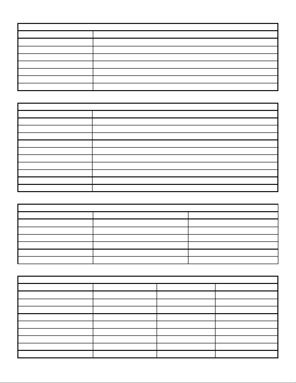
TABLE 1: 3-LEVEL MODES OF OPERATION
MODE NUMBER WIRES ACTIVATED
L1 GRN/BLK (LEVEL-1)
L2 WHT/BLK
L1 + L2 GRN/BLK & WHT/BLK (LEVEL-2)
L3 RED/BLK
L1 + L3 GRN/BLK & RED/BLK
L2 + L3 WHT/BLK & RED/BLK
L1 + L2 + L3 GRN/BLK, WHT/BLK, & RED/BLK (LEVEL-3)
TABLE 2: PATTERN SELECTION WIRES
WIRE COLOR PAIR OF HEADS CONTROLLED
GRN/WHT FRONT OUTBOARD
BLU/BLK FRONT INBOARD
GRN FRONT CORNER
BLK/WHT REAR OUTBOARD
RED/WHT REAR INBOARD
BLU/WHT REAR CENTER
BLU REAR CORNER
BLK REAR UPPER / END FLASH
WHT MULTI-COLOR ALLEY
ORG/BLK MULTI-COLOR TAKEDOWN
TABLE 3: PRIMARY/SECONDARY LAMP COLORS
MULTI-COLOR LAMPS PRIMARY COLOR SECONDARY COLOR
RED/BLUE RED BLUE
RED/AMBER RED AMBER
RED/WHITE RED WHITE
BLUE/AMBER BLUE AMBER
BLUE/WHITE BLUE WHITE
AMBER/WHITE AMBER WHITE
TABLE 4: FACTORY DEFAULT EMERGENCY WARNING FLASH PATTERNS (PROGRESSIVE SWITCH)
LAMP POSITION LEVEL-1 DEFAULT LEVEL-2 DEFAULT LEVEL-3 DEFAULT
FRONT OUTBOARD NULL FLASH (13) FAST QUAD (1) CYCLE FLASH (12)
FRONT INBOARD NULL FLASH (13) FAST QUAD (1) CYCLE FLASH (12)
FRONT CORNER NULL FLASH (13) FAST QUAD (1) CYCLE FLASH (12)
REAR OUTBOARD FAST QUAD (1) FAST QUAD (1) CYCLE FLASH (12)
REAR INBOARD FAST QUAD (1) FAST QUAD (1) CYCLE FLASH (12)
REAR CENTER FAST QUAD (1) FAST QUAD (1) CYCLE FLASH (12)
REAR CORNER FAST QUAD (1) FAST QUAD (1) CYCLE FLASH (12)
REAR UPPER / END FLASH FAST QUAD (1) FAST QUAD (1) CYCLE FLASH (12)
MULTI-COLOR ALLEY FAST QUAD (1) FAST QUAD (1) CYCLE FLASH (12)
3
Page 4

TABLE 5A: EMERGENCY WARNING FLASH PATTERNS
STANDARD FLASH PATTERNS
PATTERN NUMBER PATTERN DESCRIPTION
1 FAST QUAD 80FPM
2 SLOW QUAD 60FPM
3 FAST SINGLE 375FPM
4 MEDIUM SINGLE 115FPM
5 SLOW SINGLE 60FPM
6 FAST DOUBLE 115FPM
7 SLOW DOUBLE 60FPM
8 FAST SIX 80FPM
9 SLOW SIX 60FPM
10 VARIABLE RATE SINGLE
11 NFPA QUAD 75FPM
12 CYCLE FLASH
13 NULL FLASH (OFF)
PRIMARY ONLY PATTERNS
PATTERN NUMBER PATTERN DESCRIPTION
14 FAST QUAD 80FPM
15 SLOW QUAD 60FPM
16 FAST SINGLE 375FPM
17 MEDIUM SINGLE 115FPM
18 SLOW SINGLE 60FPM
19 FAST DOUBLE 115FPM
20 SLOW DOUBLE 60FPM
21 FAST SIX 80FPM
22 SLOW SIX 60FPM
23 VARIABLE RATE SINGLE
24 NFPA QUAD 75FPM
25 CYCLE FLASH
4
Page 5
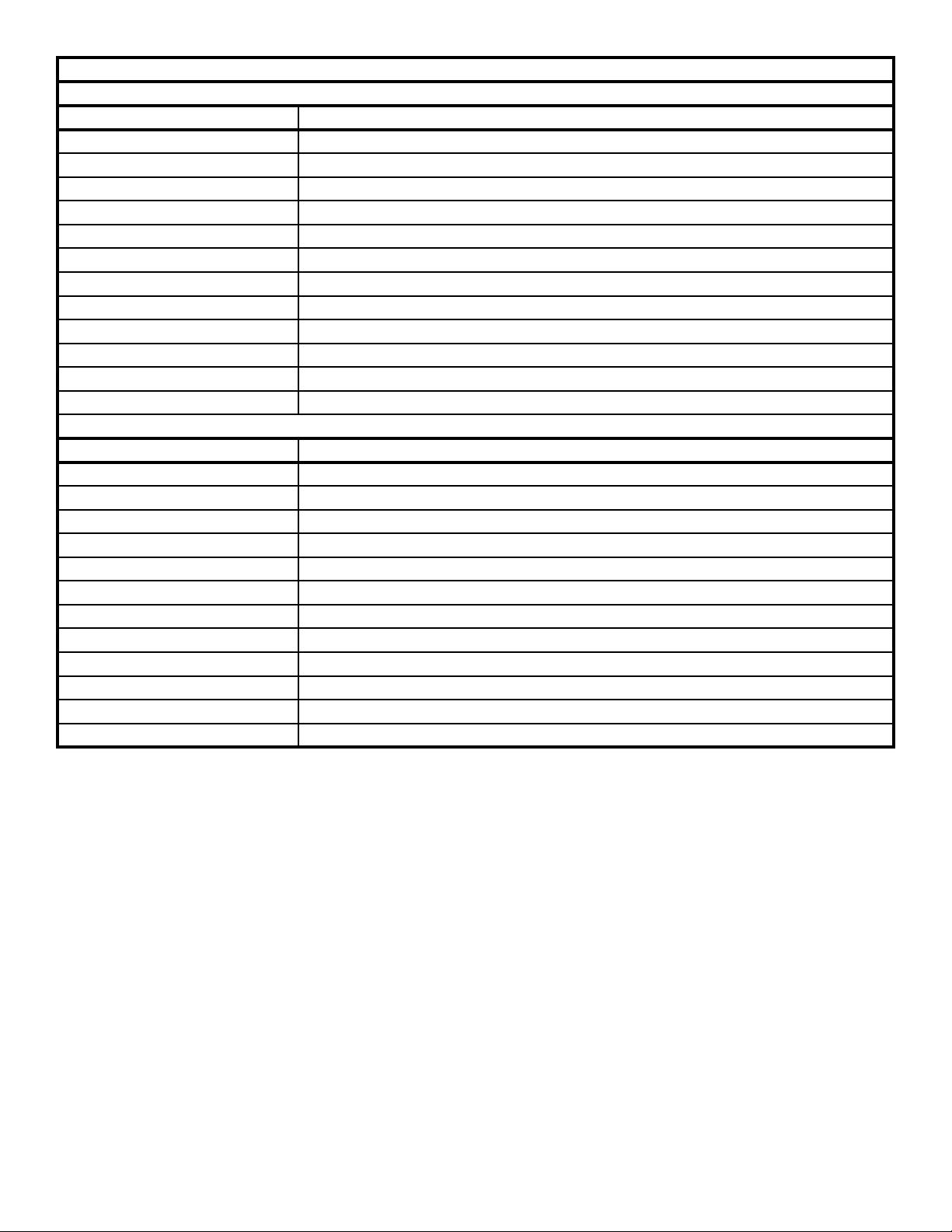
TABLE 5B: EMERGENCY WARNING FLASH PATTERNS (CONTINUED)
SECONDARY ONLY PATTERNS
PATTERN NUMBER PATTERN DESCRIPTION
26 FAST QUAD 80FPM
27 SLOW QUAD 60FPM
28 FAST SINGLE 375FPM
29 MEDIUM SINGLE 115FPM
30 SLOW SINGLE 60FPM
31 FAST DOUBLE 115FPM
32 SLOW DOUBLE 60FPM
33 FAST SIX 80FPM
34 SLOW SIX 60FPM
35 VARIABLE RATE SINGLE
36 NFPA QUAD 75FPM
37 CYCLE FLASH
PRIMARY DRIVER’S SIDE / SECONDARY PASSENGER’S SIDE PATTERNS
PATTERN NUMBER PATTERN DESCRIPTION
38 FAST QUAD 80FPM
39 SLOW QUAD 60FPM
40 FAST SINGLE 375FPM
41 MEDIUM SINGLE 115FPM
42 SLOW SINGLE 60FPM
43 FAST DOUBLE 115FPM
44 SLOW DOUBLE 60FPM
45 FAST SIX 80FPM
46 SLOW SIX 60FPM
47 VARIABLE RATE SINGLE
48 NFPA QUAD 75FPM
49 CYCLE FLASH
5
Page 6

ArrowStik® Modules:
Selecting the ArrowStik® Pattern:
The Central Controller is designed to offer user selectable traffi c directing and traffi c warning fl ash patterns. Each of
the ArrowStik functions (LEFT, CENTER-OUT, RIGHT or FLASH) can be programmed individually for unique patterns
and fl ash rates. This allows the greatest fl exibility when controlling the various light bar confi gurations available. The
light bar will come from the factory with the Building pattern as the default for LEFT, CENTER-OUT and RIGHT. The
default pattern for FLASH is the Standard Flash. If it is desired to change the pattern for any of the functions, follow the
programming procedure below.
STEP 1:
Power-up the light bar. Apply +power to the appropiate wire for the ArrowStik function that you wish to program (LEFT RED, CENTER-OUT - RED and ORG, RIGHT - ORG or FLASH - WHT). Programming will not work if more than one
function is selected at a time.
STEP 2:
Continue applying power to the wire from Step 1. Refer to Table 6 for the available fl ash patterns.
To increment to the next pattern, momentarily hold the BLK/RED wire to +power for less than two seconds and then
release. The four corner light heads will turn on steady to indicate that the pattern has been incremented.
To decrement to the previous pattern, momentarily hold the BLK/RED wire to +power for two to four seconds and
then release. The four corner light heads will turn on steady and then turn off to indicate that the pattern has been
decremented.
After the pattern selection wire has been released, the new pattern will begin to fl ash and is automatically stored each
time.
Notice that for the LEFT, CENTER-OUT and RIGHT functions there are four pattern choices (Building, Building with 3
Flash, Traveling Ball with 3 fl ash, and Build/Collapse) and three speeds (Fast, Medium and Slow). There are a total of
twelve possible selections for each function and then you return to the top selection.
For the FLASH function there are nine traffi c warning patterns available. Flash patterns marked with an asterisk “*” can
be selected in Fast, Medium or Slow fl ash rate.
NOTE: To restore the Factory Default ArrowStik Flash Pattern for any traffi c direction mode, hold the BLK/RED
wire to +power for more than four seconds. The four corner light heads will turn on steady, turn off and then turn
on steady again to indicate that the Factory Default ArrowStik Flash Pattern has been restored. Only the traffi c
direction mode that is activated will be restored.
STEP 3:
Repeat steps 1 through 2 for the other ArrowStik functions as desired.
TABLE 6: TRAFFIC DIRECTING / TRAFFIC WARNING FLASH PATTERNS
Mode LEFT CENTER-OUT RIGHT FLASH
1 Building Building Building Standard Flash*
2 Building, 3 Flash Building, 3 Flash Building, 3 Flash Quad Flash Standard
3 Traveling Ball, 3 Flash Traveling Ball, 3 Flash Traveling Ball, 3 Flash Simultaneous Flash*
4 Build/Collapse Build/Collapse Build/Collapse Quad Flash Simultaneous
5 Even/Odd Flash*
6 Quad Flash Even/Odd
7 Left/Right Flash*
8 Quad Flash Left/Right
9 Traveling Ball Flash*
All Patterns have a fast,
medium, or slow speed.
All Patterns have a fast,
medium, or slow speed.
All Patterns have a fast,
medium, or slow speed.
Patterns with the * have a fast,
medium, or slow speed.
6
Page 7

Take Down and Alley Light Modules:
Selecting Flash Patterns:
The Take Down and Alley Lights can be programmed to fl ash at different rates.
Note: The white color for Multi-Color Take Down and Alley lightheads may also be programmed as noted below.
STEP 1:
Power-up the light bar. Select the Take Down Flash Mode (BLK) or the Alley Flash Mode (BLU/WHT) by applying +power
to the appropriate wire. Programming will not work if more than one function is selected at a time.
STEP 2:
Continue applying power to the wire from Step 1. Refer to Table 7 for the available fl ash patterns.
To increment to the next pattern, momentarily hold the BLK/RED wire to +power for less than two seconds and then
release. The four corner light heads will turn on steady to indicate that the pattern has been incremented.
To decrement to the previous pattern, momentarily hold the BLK/RED wire to +power for two to four seconds and
then release. The four corner light heads will turn on steady and then turn off to indicate that the pattern has been
decremented.
After the pattern selection wire has been released, the new pattern will begin to fl ash and is automatically stored each
time.
NOTE: To restore the Factory Default Take Down or Alley Flash Pattern, hold the BLK/RED wire to +power for
more than four seconds. The four corner light heads will turn on steady, turn off and then turn on steady again
to indicate that the Factory Default Take Down or Alley Flash Pattern has been restored. The default fl ash pattern
for Take Down and Alley Lights is Medium Single 115FPM.
STEP 3:
Repeat steps 1 through 2 for the Take Down Flash Mode or the Alley Flash Mode as desired.
TABLE 7: TAKE DOWN AND ALLEY FLASH PATTERNS
PATTERN NUMBER PATTERN DESCRIPTION
1 FAST QUAD 80FPM
2 SLOW QUAD 60FPM
3 FAST SINGLE 375FPM
4 MEDIUM SINGLE 115FPM
5 SLOW SINGLE 60FPM
6 FAST DOUBLE 115FPM
7 SLOW DOUBLE 60FPM
8 FAST SIX 80FPM
9 SLOW SIX 60FPM
10 VARIABLE RATE SINGLE
11 NFPA QUAD 75FPM
12 CYCLE FLASH
.
7
Page 8

Secondary Take Down And Alley Light Modules:
Selecting Secondary Take Down and Alley Light Functions:
If the light bar is confi gured with Multi-Color lightheads in the Front:
The Front Cut wire (GRN/WHT) can be confi gured to activate the Front Multi-Color lightheads as a Second Take Down
mode (see Table 8).
The Take Down wire (ORG/BLK) may also be confi gured to activate the Front Multi-Color light heads as a Third Take
Down mode (see Table 11).
If the light bar is confi gured with Multi-Color lightheads in the Corners:
The Rear Cut wire (BLU/BLK) can be confi gured to operate Second Right Alley mode (see Table 9).
The Right Alley wire (RED/WHT) can be confi gured to operate Thrid Right Alley mode (see Table 12).
The Cruise wire (GRN) can be confi gured to operate Second Left Alley Light mode (see Table 10).
The Left Alley wire (BLK/WHT) can be confi gured to operate Third Left Alley Light mode (see Table 13).
Other programmable functions include:
The Rear Cut wire (BLUE/BLK) can be confi gured for multiple Rear Work Light functions (see Table 9 for work light
options).
The Cruise wire (GRN) can be confi gured for multiple Cruise functions (see Table 10 for cruise options).
NOTE: If the Front Cut wire (GRN/WHT) is confi gured to activate the Front Multi-Color lightheads as Secondary
Take Downs, the standard Front Cut function will be disabled. If the Rear Cut wire (BLU/BLK) is confi gured to
activate the Corner Multi-Color lightheads as Secondary Alley Lights, the standard Rear Cut function will be
disabled. If the Cruise wire (BLU/BLK) is confi gured to activate the Corner Multi-Color lightheads as Secondary
Alley Lights, the standard Cruise function will be disabled.
STEP 1:
Power up the light bar. Select one of the following:
For second mode; Front Cut function (GRN/WHT) or the Rear Cut function (BLU/BLK) or the Cruise function (GRN) by
applying +power to the appropriate wire. Programming will not work if more than one function is selected at a time.
For third mode; Take Down function (ORG/BLK) or the Right Alley function (RED/WHT) or the Left Alley function (BLK/
WHT) by applying +power to the appropriate wire. Programming will not work if more than one function is selected
at a time.
NOTE: If the Front Cut wire (GRN/WHT) is confi gured for the Front Cut function, no lightheads will be activated
when +power is applied to the GRN/WHT wire. If the Rear Cut wire (BLU/BLK) is confi gured for the Rear Cut
function, no lightheads will be activated when +power is applied to the BLU/BLK wire.
STEP 2:
Continue applying power to the wire from Step 1. Refer to Table 8 for the available Front Cut functions, Table 9 for the
available Rear Cut Functions, Table 10 for the available Cruise Light functions, Table 11 for Take Down functions, Table 12
for Right Alley functions, or Table 13 for Left Alley functions.
To increment to the next function, momentarily hold the BLK/RED wire to +power for less than two seconds and then
release. The four corner light heads will turn on steady to indicate that the function has been incremented.
To decrement to the previous function, momentarily hold the BLK/RED wire to +power for two to four seconds and
then release. The four corner light heads will turn on steady and then turn off to indicate that the function has been
decremented.
After the BLK/RED wire has been released, the new function will begin to operate and is automatically stored each time.
NOTE: To restore the Factory Default Secondary Take Down and Alley Light Functions, hold the BLK/RED wire
to +power for more than four seconds. The four corner light heads will turn on steady, turn off and then turn
on steady again to indicate that the Factory Default Secondary Take Down and Alley Light Functions have been
restored. The default function for the Front Cut, Rear Cut, Cruise, Take Down, Right Alley, and Left Alley wires is
function number 1 as shown in Tables 8, 9, 10, 11, 12, and 13. Only the function that is activated will be restored.
STEP 3:
Repeat steps 1 through 2 for the Front Cut function, Rear Cut function, Cruise function, Take Down, Right Alley, and Left
Alley as desired.
8
Page 9

TABLE 8: FRONT CUT (GRN/WHT) FUNCTIONS
FUNCTION NUMBER FUNCTION DESCRIPTION
1 STANDARD FRONT CUT FUNCTION
2 WHITE FRONT OUTBOARD LIGHTHEADS**
3 WHITE FRONT INBOARD LIGHTHEADS**
4 WHITE ALL FRONT LIGHTHEADS**
5 WHITE FRONT OUTBOARDS AND CORNER LIGHTHEADS**
6 WHITE FRONT INBOARDS AND CORNER LIGHTHEADS**
7 WHITE ALL FRONT AND CORNER LIGHTHEADS**
8 RED/BLUE OUTBOARD LIGHTHEADS*
9 RED/BLUE INBOARD LIGHTHEADS*
10 RED/BLUE ALL FRONT LIGHTHEADS*
11 RED/BLUE OUTBOARD AND CORNER LIGHTHEADS*
12 RED/BLUE INBOARD AND CORNER LIGHTHEADS*
13 RED/BLUE ALL FRONT AND CORNER LIGHTHEADS*
TABLE 9: REAR CUT (BLU/BLK) FUNCTIONS
FUNCTION NUMBER FUNCTION DESCRIPTION
1 STANDARD REAR CUT FUNCTION
2 WHITE FRONT RIGHT CORNER LIGHTHEAD**
3 WHITE REAR RIGHT CORNER LIGHTHEAD**
4 RED/BLUE FRONT RIGHT CORNER LIGHTHEAD*
5 RED/BLUE REAR RIGHT CORNER LIGHTHEAD*
6 WHITE REAR OUTBOARD LIGHTHEADS**
7 WHITE REAR INBOARD LIGHTHEADS**
8 WHITE REAR CENTER LIGHTHEADS**
9 WHITE REAR INBOARD AND CENTER LIGHTHEADS**
10 WHITE REAR UPPER LIGHTHEADS**
11 WHITE REAR ALL LIGHTHEADS**
12 WHITE REAR OUTBOARD AND CORNER LIGHTHEADS**
13 WHITE REAR INBOARD AND CORNER LIGHTHEADS**
14 WHITE REAR CENTER AND CORNER LIGHTHEADS**
15 WHITE REAR UPPER AND CORNER LIGHTHEADS**
16 WHITE REAR ALL AND CORNER LIGHTHEADS**
TABLE 10: CRUISE FUNCTIONS
FUNCTION NUMBER FUNCTION DESCRIPTION
1 CRUISE PRIMARY LAMPS ONLY
2 CRUISE SECONDARY LAMPS ONLY
3 CRUISE PRIMARY DRIVER’S SIDE / SECONDARY PASSENGER’S SIDE
4 FLICKER ALL CRUISE PRIMARY LAMPS ONLY
5 FLICKER ALL CRUISE SECONDARY LAMPS ONLY
6 FLICKER ALL CRUISE PRIMARY DRVR’S SIDE / SECONDARY PASSGR’S SIDE
7 WHITE LEFT FRONT CORNER LIGHTHEAD**
8 WHITE LEFT REAR CORNER LIGHTHEAD**
9 RED/BLUE LEFT FRONT CORNER LIGHTHEAD*
10 RED/BLUE LEFT REAR CORNER LIGHTHEAD*
9
Page 10

TABLE 11: TAKE DOWN (ORG/BLK) FUNCTIONS
FUNCTION NUMBER FUNCTION DESCRIPTION
1 STANDARD TAKE DOWN FUNCTION
2 TAKE DOWN AND WHITE FRONT OUTBOARD LIGHTHEADS**
3 TAKE DOWN AND WHITE FRONT INBOARD LIGHTHEADS**
4 TAKE DOWN AND WHITE ALL FRONT LIGHTHEADS**
5 TAKE DOWN AND WHITE FRONT OUTBOARDS AND CORNER LIGHTHEADS**
6 TAKE DOWN AND WHITE FRONT INBOARDS AND CORNER LIGHTHEADS**
7 TAKE DOWN AND WHITE ALL FRONT AND CORNER LIGHTHEADS**
8 TAKE DOWN AND RED/BLUE OUTBOARD LIGHTHEADS*
9 TAKE DOWN AND RED/BLUE INBOARD LIGHTHEADS*
10 TAKE DOWN AND RED/BLUE ALL FRONT LIGHTHEADS*
11 TAKE DOWN AND RED/BLUE FRONT OUTBOARD AND CORNER LIGHTHEADS*
12 TAKE DOWN AND RED/BLUE FRONT INBOARD AND CORNER LIGHTHEADS*
13 TAKE DOWN AND RED/BLUE ALL FRONT AND CORNER LIGHTHEADS*
TABLE 12: RIGHT ALLEY (RED/WHT) FUNCTIONS
FUNCTION NUMBER FUNCTION DESCRIPTION
1 STANDARD RIGHT ALLEY FUNCTION
2 RIGHT ALLEY AND WHITE FRONT RIGHT CORNER LIGHTHEAD**
3 RIGHT ALLEY AND WHITE REAR RIGHT CORNER LIGHTHEAD**
4 RIGHT ALLEY AND RED/BLUE FRONT RIGHT CORNER LIGHTHEAD*
5 RIGHT ALLEY AND RED/BLUE REAR RIGHT CORNER LIGHTHEAD*
TABLE 13: LEFT ALLEY (BLK/WHT) FUNCTIONS
FUNCTION NUMBER FUNCTION DESCRIPTION
1 STANDARD LEFT ALLEY FUNCTION
4 LEFT ALLEY AND WHITE FRONT LEFT CORNER LIGHTHEAD**
5 LEFT ALLEY AND WHITE REAR LEFT CORNER LIGHTHEAD**
6 LEFT ALLEY AND RED/BLUE FRONT LEFT CORNER LIGHTHEAD*
7 LEFT ALLEY AND RED/BLUE REAR LEFT CORNER LIGHTHEAD*
*RED/BLUE Functions will activate both colors in the Multi-Color lighthead and are designed for use in RED/BLUE lightheads only. When the RED/BLUE lightheads are activated together the colors will blend creating the effect of a WHITE
lighthead when veiwed from a distance.
**WHITE ONLY Functions will activate only the secondary color in the Multi-Color lighthead and are designed for use in
RED/WHITE, BLUE/WHITE and AMBER/WHITE lightheads only.
10
Page 11
Rear Upper / End Flash Modules:
Selecting the Rear Upper / End Flash Pattern:
The Central Controller is designed to offer user selectable Rear Upper (Solex) or End Flash (21TR) fl ash patterns. This
feature allows the Rear Upper or End Flash lamps to Alternate whenever any of the ArrowStik functions (LEFT, CENTEROUT, RIGHT or FLASH) are activated. The light bar will come from the factory with the Rear Upper / End Flash feature in
the Off pattern. If it is desired to change the pattern, follow the programming procedure below.
STEP 1:
Power-up the light bar. Apply +power to one of the ArrowStik functions (LEFT - RED, CENTER-OUT - RED and ORG or
RIGHT - ORG). Programming will not work if more than one function is selected at a time.
STEP 2:
Continue applying power to the wire from Step 1. Refer to Table 14 for the available fl ash patterns.
To increment to the next pattern, momentarily hold the BLK and BLK/RED wires to +power for less than two seconds and
then release. The four corner light heads will turn on steady to indicate that the pattern has been incremented.
To decrement to the previous pattern, momentarily hold the BLK and BLK/RED wires to +power for two to four seconds
and then release. The four corner light heads will turn on steady and then turn off to indicate that the pattern has been
decremented.
After the pattern selection wires have been released, the new pattern will begin to fl ash and is automatically stored each
time.
NOTE: To restore the Factory Default Rear Upper / End Flash Pattern, hold the BLK and BLK/RED wires to
+power for more than four seconds. The four corner light heads will turn on steady, turn off and then turn on
steady again to indicate that the Factory Default Pattern has been restored. Selecting the Rear Upper / End Flash
Pattern for one ArrowStik function will select this pattern for all ArrowStik functions.
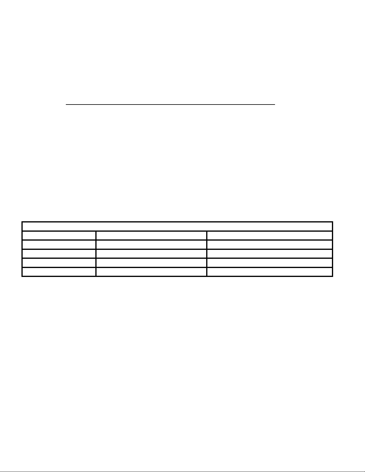
TABLE 14: REAR UPPER / END FLASH PATTERNS
PATTERN NUMBER MULTI-COLOR LAMPS SINGLE COLOR LAMPS
1 Off Off
2 Alternating Multi-Color Alternating
3 Alternating Primary Only
4 Alternating Secondary Only
11
Page 12

WARRANTY
Code 3®, Inc.’s emergency devices with Torus® Technology are tested and found to be operational at the time of
manufacture. Provided this product is installed and operated in accordance with the manufacturer's recommendations,
Code 3, Inc. warrants all parts and components (with the exception of all incandescent and halogen bulbs) of the product
to be free of defects in material and workmanship for a period of one (1) year and Torus light heads for a period of fi ve
(5) years from the date of purchase. This Warranty excludes normal wear & tear. Units demonstrated to be defective
within the warranty period will be repaired or replaced at the factory service center at no cost. Code 3, Inc. will return
the repaired product with transportation cost prepaid. Code 3, Inc. assumes no liability for expenses incurred in the
packaging, handling, and shipping of the product to the Factory Technical Service Department for repair. For in-warranty
product return authorization, questions regarding product warranty coverage or questions regarding out-of-warranty
repair quotes, contact the Factory Technical Service Department.
This Warranty is void if, in the judgment of Code 3, Inc. (1) an attempt has been made to repair the light head, and/
or (2) the product has been used with inappropriate or inadequate wiring or circuit protection, and/or (3) the product has
failed as a result of abuse or unusual use and/or accidents.
CODE 3, INC. SHALL IN NO WAY BE LIABLE FOR ANY OTHER DAMAGES RELATING TO THE PRODUCT
INCLUDING BUT NOT LIMITED TO CONSEQUENTIAL, INCIDENTAL, INDIRECT OR SPECIAL DAMAGES OR
LOST PROFITS OR REVENUE; NOR ANY EXPENSES INCURRED IN THE REMOVAL AND/OR RE-INSTALLATION OF PRODUCTS REQUIRING SERVICE AND/OR REPAIR.
EXCEPT AS SET FORTH ABOVE, CODE 3, INC. MAKES NO OTHER EXPRESS OR IMPLIED WARRANTIES WHATSOEVER, INCLUDING, WITHOUT LIMITATION, WARRANTIES OF FITNESS FOR A PARTICULAR
PURPOSE OR MERCHANTABILITY, WITH RESPECT TO THIS PRODUCT.
Problems or Questions? Call The Technical Assistance HOT LINE - (314) 996-2800
PRODUCT RETURNS
If a product must be returned for repair or replacement*, please contact our factory to obtain a
Return Goods Authorization Number (RGA number) before you ship the product to Code 3®, Inc.
Write the RGA number clearly on the package near the mailing label. Be sure you use suffi cient
packing materials to avoid damage to the product being returned while in transit.
*Code 3®, Inc. reserves the right to repair or replace at its discretion. Code 3®, Inc. assumes no responsibility or liability for expenses incurred for the removal and /or
reinstallation of products requiring service and/or repair.; nor for the packaging, handling, and shipping: nor for the handling of products returned to sender after the service has been
rendered.
Code 3®, Inc.
St. Louis, Missouri 63114-2029—USA
Ph. (314) 426-2700 Fax (314) 426-1337
10986 N. Warson Road
www.code3pse.com
Code 3 is a registered trademark of Code 3, Inc.
12
Revision 2, 06/14 - Supplement No. T51599
©2014 Printed in USA
 Loading...