

Page 1
INSTALLATION
& OPERATION
MANUAL
21TRTM AND 21TR PLUSTM LIGHTBAR
21TR
For future reference record your lightbar's serial no. here __________________________________________
IMPORTANT:
TM
CONTENTS:
TM
and 21TR Plus
LIGHTBAR
Introduction...................................................................................2
Unpacking & Pre-Installation.........................................................2
Installation & Mounting..........................................................3-4
Wiring Instructions - 21TRTM..............................................................5-8
Wiring Instructions - 21TR PlusTM...................................................9-12
Takedown & Alley Lights..................................................................13-14
Maintenance.........................................................................15
Parts List (Replacement Parts / Exploded View) & Troubleshooting.............16
Warranty.....................................................................................17
Read all instructions and warnings before installing and using.
INSTALLER: This manual must be delivered to the end user of this equipment.
1
Page 2
Introduction
The 21TR™ & 21TR PlusTM Light Bar is a light bar that is approximately 2" high, yet delivers unobstructed 360° warning and more signal
power and versatility than any other light bar of its size through the use of newly designed Torus TechnologyTM optics. The low prole
and aerodynamic lines reduce air drag, which results in fuel savings and stability at high speeds. This light bar has a strong extruded
internal frame, shock-resistant polycarbonate lenses, and warning signals that exceed SAE standards. The light bar is designed on a
modular basis, which means that the light bar can be customized to meet any requirement. It has room for numerous halogen and
LED options, and offers the ultimate exibility in the location of warning and auxiliary lights.
The use of this or any warning device does not ensure that all drivers can or will observe or react to an
emergency warning signal. Never take the right-of-way for granted. It is your responsibility to be sure you can
proceed safely before entering an intersection, driving against trafc, responding at a high rate of speed, or
walking on or around trafc lanes.
The effectiveness of this warning device is highly dependent upon correct mounting and wiring. Read and
follow the manufacturer’s instructions before installing or using this device. The vehicle operator should insure
daily that all features of the device operate correctly. In use, the vehicle operator should insure the projection
of the warning signal is not blocked by vehicle components (i.e.: open trunks or compartment doors), people,
vehicles, or other obstructions.
!
WARNING!
This equipment is intended for use by authorized personnel only. It is the user’s responsibility to understand
and obey all laws regarding emergency warning devices. The user should check all applicable city, state and
federal laws and regulations.
Code 3, Inc., assumes no liability for any loss resulting from the use of this warning device.
Proper installation is vital to the performance of this warning device and the safe operation of the emergency
vehicle. It is important to recognize that the operator of the emergency vehicle is under psychological and
physiological stress caused by the emergency situation. The warning device should be installed in such a
manner as to: A) Not reduce the output performance of the system, B) Place the controls within convenient
reach of the operator so that he can operate the system without losing eye contact with the roadway.
Emergency warning devices often require high electrical voltages and/or currents. Properly protect and use
caution around live electrical connections. Grounding or shorting of electrical connections can cause high cur-
rent arcing, which can cause personal injury and/or severe vehicle damage, including re.
PROPER INSTALLATION COMBINED WITH OPERATOR TRAINING IN THE PROPER USE OF EMERGENCY WARNING DEVICES IS ESSENTIAL TO INSURE THE SAFETY OF EMERGENCY PERSONNEL AND
THE PUBLIC.
Wiring Instructions (read Carefully Before Installation)
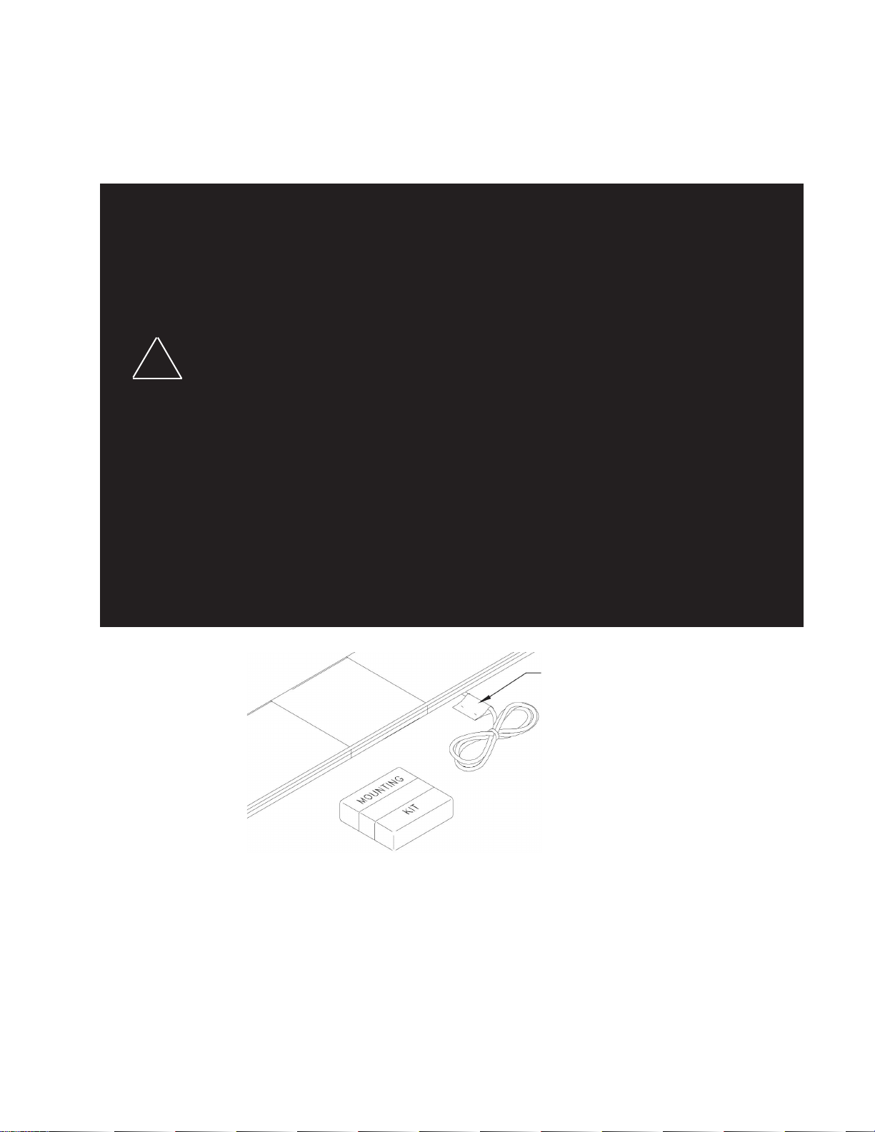
Unpacking & Pre-installation
Carefully remove the light bar and place it on a at surface, taking care not to scratch the lenses or damage the cable coming out of the
bottom. Examine the unit for transit damage, broken lamps, etc. Report any damage to the carrier and keep the shipping carton.
Standard light bars are built to operate on 12 volt D.C. negative ground (earth) vehicles. If you have an electrical system other than 12
volt D.C. negative ground (earth), and have not ordered a specially wired light bar, contact the factory for instructions.
Test the unit before installation. To test, touch the black wire to the ground (earth) and the other wires to +12 volts D.C., in accordance
with the instructions attached to the cable (an automotive battery is preferable for this test). A battery charger may be used, but please
note that some electronic options (ashers, etc.) may not operate normally when powered by a battery charger. If problems occur at
this point, contact the factory.
2
Page 3
Installation & Mounting
Utilizing non-factory supplied screws and/or mounting brackets and/or the improper
WARNING!
!
Mounting Hardware
All mounting hardware is packed in a small box inside the main carton. Four standard kits are available: (1) Hook-On Type, (1) Tow and
Recovery and (2) Permanent Types. These are discussed in detail later. Note: Hook-on mounting for "gutterless" type vehicles will
require a special hook for mounting. Several special application hooks are available. Contact the factory for details.
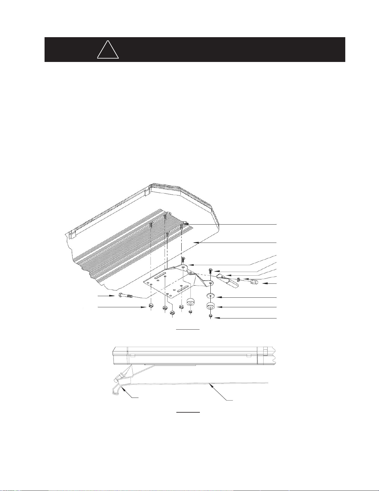
Hook-on Mounting
Begin the installation by attaching the rubber feet to the mounting brackets using the black 1/4" carriage bolts and 1/4" nuts provided.
See Figure 1. (Do not install shims at this time). Place the light bar upside down on a table or other work surface, being careful not to
scratch the lenses. Slide the 5/16" carriage bolts into the frame. Secure the mounting brackets nger tight so they support the weight
of the light bar, but can still be positioned. Locate the vehicle on a level surface. Place the light bar on the roof of the vehicle. Place
a soft pad in the center of the roof to protect the paint. The mounting brackets must be placed so that the rubber feet are resting on
the curved section of the roof, see Figure 2. This is the strongest part of the roof. Once the light bar is centered, tighten the mounting
bracket to the light bar. Using a tape measure and a level, center the light bar from side to side and locate a position on the roof where
the light bar is level.
number of screws may result in loss of warranty coverage on the equipment.
5/16" Cap Screw
5/16" Nut
Curved Feet on
Curved Portion
Vehicle Gutter
5/16-18 Carriage Bolt
Bottom of Lightbar
Mounting Bracket
1/4-20 Carriage Bolt
Gutter Hook
5/16" Split Lockwasher
5/16" Trim Nut
(Do Not Overtighten)
Plastic Shim (if needed)
Rubber Foot
1/4" Acorn Nut
FIGURE 1
Vehicle Roof
FIGURE 2
The shims provided may be used here to help level the light bar, see Figure 1. Also, the tabs on the mounting brackets may be bent at
any angle to match the curvature of the roof. Select the appropriate length cap screw and insert through the holes in the gutter hook
and mounting bracket, and into a lock washer and acorn nut as shown in Figure 1. If a special hook for a "gutterless" vehicle is used,
refer to the instructions for that hook at this time. The stainless steel cap screws supplied are sized for the most common installations,
but longer and shorter bolts are available at any hardware store. Tighten the cap screws on both sides evenly keeping the light bar
centered and level.
3
Page 4
NOTE: Tighten only until the bar is secure (bar does not move when bumped sharply with the heel of the palm). It is NOT necessary to
dimple the roof to obtain a stable attachment. If the light bar "bows" more than 3/16" (determined by placing a straightedge along the
front, bottom part of the frame and measuring downward at the center of the frame), loosen the 5/16" trim nut sightly.
Re-Installation: When moving a light bar from one vehicle to another, we suggest that new rubber feet be used. These are standard
hardware items, and can usually be found at any hardware store, or can be ordered from the factory. The special hooks are stainless
steel and should be saved and reused. Mounting kit parts are available to permit remounting on vehicles of different design or make.
Consult your local dealer or Code 3 , Inc. for detailed information.
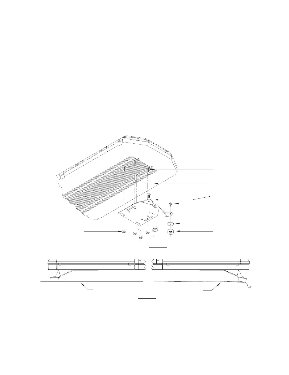
Permanent Mounting
Typical Mounting: Refer to Figure 3. Place the light bar upside down on a table or other work surface, being careful not to scratch
the lenses. Slide the 5/16" carriage bolts into the frame. Secure the mounting brackets nger tight so they support the weight of the
light bar. Place the unit on the roof of the vehicle. Place a soft pad in the center of the roof to protect the paint. The mounting brackets
must be placed so that they are resting on the curved section of the roof, see Figure 4. This is the strongest part of the roof. Once
the light bar is centered, tighten mounting brackets to light bar. Using a tape measure and a level, center the light bar from side
to side and locate a position of the roof where the light bar is level. The shims provided may be used here to help level the light
bar. Also, the tabs on the mounting bracket may be bent at any angle to match the curvature of the roof (see Figure 4).
5/16" Nut
Flat Roof
FIGURE 3
FIGURE 4
Curved Roof
5/16-18 Carriage Bolt
Bottom of Lightbar
Mounting Bracket
Customer Supplied Bolt
Plastic Shim (if needed)
Rubber Foot
Place Feet on
Curved Portion
Once the light bar is level and centered, mark the holes through the mounting tabs and remove the light bar from the vehicle. Make
sure that the drill will not damage anything when penetrating the roof. Drill the mounting holes and remove any burrs. Attachment
can be made using 1/4" cap screws, toggle bolts, or other fasteners as may be convenient. Use sealant as necessary to prevent water
leakage into the vehicle.
4
Page 5

Wiring Instructions
Before attempting to connect wiring refer to wire tag attached to the lightbar's main cable. Each wire in the cable controls a separate
lightbar function as described in the wire tag.
Larger wires and tight connections will provide longer service life for components. For high current wires it
is highly recommended that terminal blocks or soldered connections be used with shrink tubing to protect
the connections. Do not use insulation displacement connectors (e.g. 3M® Scotchlock type connectors).
Route wiring using grommets and sealant when passing through compartment walls. Minimize the number
of splices to reduce voltage drop. High ambient temperatures (e.g. underhood) will signicantly reduce the
current carrying capacity of wires, fuses, and circuit breakers. Use "SXL" type wire in engine compartment.
All wiring should conform to the minimum wire size and other recommendations of the manufacturer and
!
WARNING!
be protected from moving parts and hot surfaces. Looms, grommets, cable ties, and similar installation
hardware should be used to anchor and protect all wiring. Fuses or circuit breakers should be located as
close to the power takeoff points as possible and properly sized to protect the wiring and devices. Particular
attention should be paid to the location and method of making electrical connections and splices to protect
these points from corrosion and loss of conductivity. Ground terminations should only be made to substantial chassis components, preferably directly to the vehicle battery. The user should install a fuse sized
to approximately 125% of the maximum Amp capacity in the supply line to protect against short circuits.
For example, a 30 Amp fuse should carry a maximum of 24 Amps. DO NOT USE 1/4" DIAMETER GLASS
FUSES AS THEY ARE NOT SUITABLE FOR CONTINUOUS DUTY IN SIZES ABOVE 15 AMPS. Circuit
breakers are very sensitive to high temperatures and will "false trip" when mounted in hot environments or
operated close to their capacity.
Routing
Route the wiring cables into the engine or passenger compartment, taking care to use grommets and to apply sealant around openings
to keep water out. It is advisable to leave an extra loop of cable when installing the light bar to allow for future changes or reinstallations.
Connect the black lead to a solid frame ground (earth), preferably, the (-) or ground (earth) side of the battery and bring the other wires
to the control head or switches. Connect the wires as directed by the wiring instructions on the cable.
5
Page 6
WARNING!
This Product contains high intensity LED devices. To prevent eye damage, DO NOT
!
stare into light beam at close range.
Fusing - 21TR
The light bar should be installed with an external fuse or circuit breaker in the RED lead of the 11 conductor cable. The recommended
external fuse size for the light bar is 15A. The internal circuitry of the Central Controller is reverse polarity protected. Each output on
the Central Controller board is protected against over current and over heating with automatically resetting output devices.
Wiring - 21TR
Connect the black lead to a solid frame ground (earth), preferably the (-) or ground (earth) side of the battery, and the power wire to
the +12V terminal of the battery. Connect the remaining wires in the 11 conductor cable as shown in Table 1.
Note: All control inputs are +power enabled.
Control Input Function Denition
Wire Color Function Description
BLUE
ORANGE
YELLOW #1 (18 GA)
LIGHT BLUE Take Down lights Take Down Lights Steady Burn (overrides Take Down Flash)
YELLOW #2 (20 GA) ******Not Used****** ******Not Used******
YELLOW/BLACK Left Alley Light Left Alley Steady Burn (overrides Alley Light Flash)
WHITE Light Bar Dimming Dims All Lighthead Modules in Lightbar Except for Corners
GREEN Pattern Select Light Bar Flash Pattern Select Wire & Diagnostic Test
BLACK Ground Ground
RED Power +12V Input Supply
BROWN Right Alley Light Right Alley Steady Burn (overrides Alley Light Flash)
Flash Pattern Selection - 21TR
The Pattern Select wire is the Green wire in the 11 conductor control cable and is activated by momentarily touching the wire to +12V.
There are seven total combinations of unique ash patterns that can be dened with a unique ash pattern. It is also important to understand whether the light bar will be controlled by a progressive style switching controller, or individual switches.
This often leads to confusion in selecting patterns and may result in the end user not achieving the desired outcome. This is
discussed in the section titled "Progressive vs. Independent Switching".
TM
TM
Level Control Wire
Table 1 - Control Wire Denitions - 21TR
Energizes light heads per the pattern chosen by the end user or, if left
unchanged, per the defaults set at the factory (see Table 2).
TM
TM
Diagnostic Test
There is also a diagnostic test that can be run using the Green pattern change wire. Apply +12V to the Green wire (only). The lights
will turn on one at a time and then turn off. At the end it should ash all emergency lights at the same time three times. Note that
it can only be activated by applying power to the Green wire at start up. If the unit has been energized with any other wire, power
needs to be removed entirely from the light bar before applying power to the Green wire to enter into this mode again.
6
Page 7

Factory Defaults - Flash Patterns
Find below the seven default ash patterns for the various combinations of wires. Reference Table 2 for all ash patterns.
Blue: Pattern 13 Fast In-Out Quad Rear
Orange: Pattern 25 Fast In-Out Quad Front
Yellow: Pattern 11 Cycle Front/Rear
Blue & Orange: Pattern 1 Fast In-Out Quad Front/Rear
Blue & Yellow: Pattern 11 Cycle Front/Rear
Orange & Yellow: Pattern 11 Cycle Front/Rear
Blue & Orange & Yellow: Pattern 11 Cycle Front/Rear
Table 2 - Flash Patterns - 21TR
Pattern Number Flash Pattern Description
1 (Default: Blue + Orange) Fast In-Out Quad Front/Rear
2 Picket Fence Single Front/Rear
3 In-Out Single Front/Rear
4 Picket Fence Quad Front/Rear
5 Picket Fence Six Front/Rear
6 Slow In-Out Quad Front/Rear
7 Slow In-Out Six Front/Rear
8 Fast In-Out Six Front/Rear
9 Variable Rate Picket Fence, Single Front/Rear
10 In-Out Quad (80 FPM, NFPA) Front/Rear
11 (Default: Yellow, Blue+Yellow, Orange+Yellow, Blue+Orange+Yellow) Cycle Front/Rear
12 Simultaneous Quad (75 FPM, NFPA) Front/Rear
13 (Default: Blue) Fast In-Out Quad Rear
14 Picket Fence Single Rear
15 In-Out Single Rear
16 Picket Fence Quad Rear
17 Picket Fence Six Rear
18 Slow In-Out Quad Rear
19 Slow In-Out Six Rear
20 Fast In-Out Six Rear
21 Variable Rate Picket Fence, Single Rear
22 In-Out Quad (80 FPM, NFPA) Rear
23 Cycle Rear
24 Simultaneous Quad (75 FPM, NFPA) Rear
25 (Default: Orange) Fast In-Out Quad Front
26 Picket Fence Single Front
27 In-Out Single Front
28 Picket FEnce Quad Front
29 Picket Fence Six Front
30 Slow In-Out Quad Front
31 Slow In-Out Six Front
32 Fast In-Out Six Front
33 Variable Rate Picket Fence, Single Front
34 In-Out Quad (80 FPM, NFPA) Front
35 Cycle Front
36 Simultaneous Quad (75 FPM, NFPA) Front
TM
7
Page 8

Progressive vs. Independent Switching
In a 3-level progressive switch application there are only 3 patterns that typically need to be set.
Example 1: Using the defaults in Table 2, the patterns displayed would be as follows as the switch is moved from the off position
through Levels 1, 2 and 3:
Level/Switch Energized
Pattern Description Notes
Wire Color
1 Blue 13 Fast In-Out Quad REAR Only Level 1 is energized.
2 Blue + Orange 1 Fast In-Out Quad FRONT/
REAR
3 Blue + Orange
+ Yellow
In an application with 2- or 3- independent switches there are "combinations" of wire colors that can have unique ash patterns
dened, thus allowing the switches to simulate a progressive style application. It is intuitive to think that only two unique ash patterns
can be displayed in a system with 2 independent switches; however, a third pattern is available. In the below scenario 2 independent
switch can mimic a 3-level progressive switch.
11 Cycle FRONT/REAR Levels 1 & 2 are still energized, there-
Level 1 is still energized, therefore
the pattern displayed is dened by
the "Blue + Orange" default. In this
instance the ash pattern chosen for
the "Orange" wire by itself (pattern 25)
does not come into play because the
switch is progressive.
fore the pattern displayed is dened by
the "Blue + Orange + Yellow" default.
In this instance, the ash patterns
chosen for the "Blue", "Orange" and
"Yellow" wires by themselves do not
come into play because the switch is
progressive.
Note: Remember that switches that are not progressive operate completely independent of each other.
Example 2: Setting Blue to Pattern 13 (which is the default), Orange to Pattern 1 (which is NOT the default), and Blue + Orange to
Pattern 11 (which is NOT the default), the patterns displayed would be as follows for a 2 independent switch application:
Level/Switch On/Off Wire Color Pattern Description Notes
1 ON Blue 13 Fast In-Out Quad REAR Only Level 1 is energized.
2 Off Orange
1 Off Blue
2 ON Orange 1 Fast In-Out Quad FRONT/
REAR
1 ON Blue
2 ON Orange
11 Cycle FRONT/REAR
Note: in the above scenarios the Blue and Orange wires are not being tied together in nal installation, however, they do need to be
tied together when setting the ash pattern for that combination of wire colors. The "Blue + Orange" description simply identies that
a unique pattern can be chosen for the scenario where both Level 1 and Level 2 are energized. In order to achieve proper operation
of the lightbar all possible combinations of the independent switches must be programmed to the desired pattern.
Only Level 2 is energized. If the ash
pattern for "Orange" had been left at
it's default factory setting (pattern 25),
then the light bar would have ashed
in a "Fast In-Out Quad FRONT" only.
Both Levels 1 & 2 are energized,
therefore the pattern displayed is de-
ned by the "Blue + Orange" pattern
that had been set by the user, which
was Pattern 11
8
Page 9
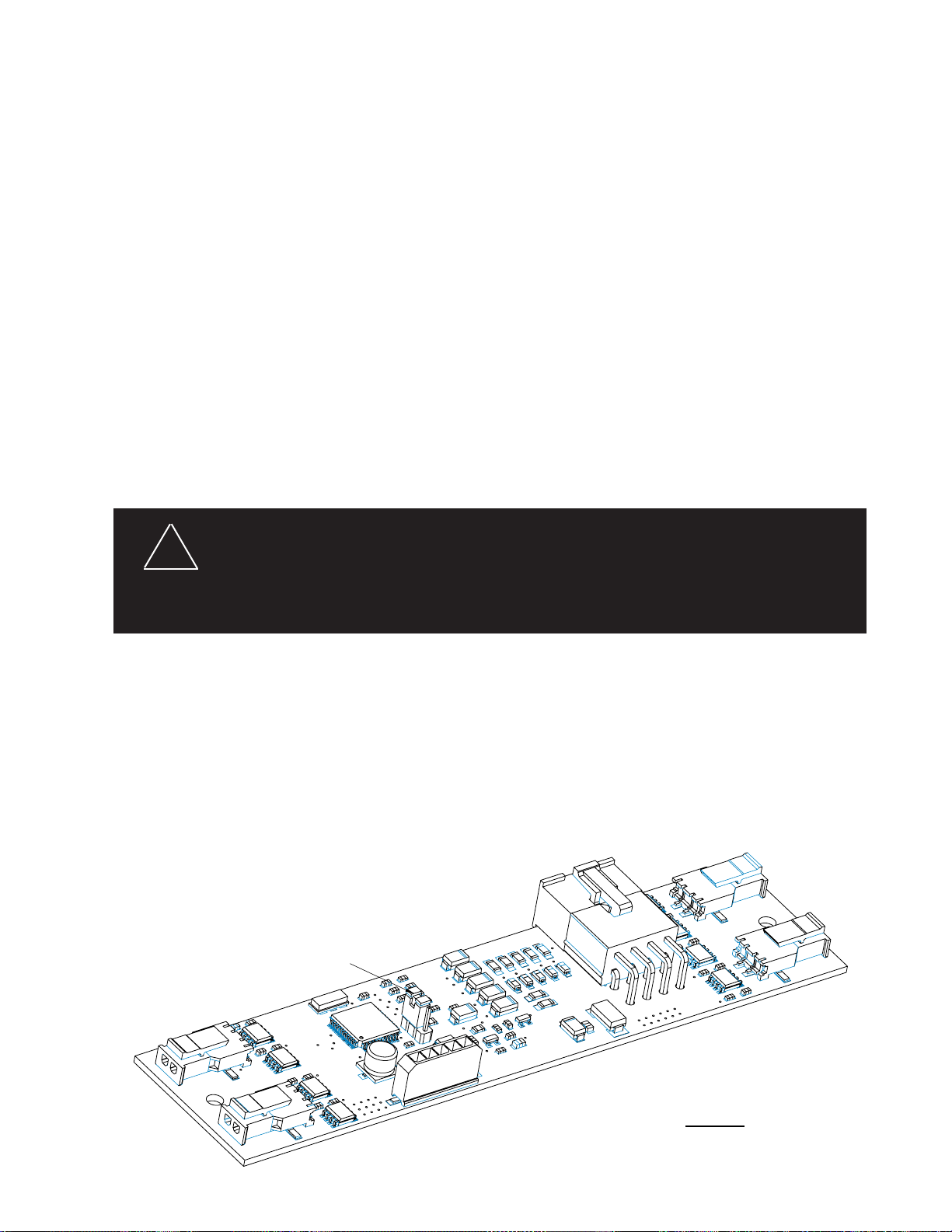
Setting Flash Patterns
Jumper - Shown in Default Position
Move jumper to next position for
Steady Burn light head operation
Jumper Position:
Default: Light head(s) connected to Blue/Black wire will operate in flashing mode.
Steady-Burn: Light heads(s) connected to Blue/Black wire will operate in steady-burn mode.
Step 1
Power-up the light bar by connecting the Red wire to +12V and the Black wire to ground, and select Level 1 on a user-purchased 3
Level controller or, if the Lightbar is not yet connected to a controller, energize Level-1 by connecting the Blue wire to +12V.
Step 2
Observe the ash pattern operation and determine which pattern is in operation for Level-1. Refer to Table 2. Note: the Factory
Default is different for each ash pattern Level. Once the ash pattern has been determined, proceed to Step 3.
Step 3
Apply +12V to the Green wire momentarily to scroll to the next ash pattern, then release the Green wire from +12V. Continue to
repeat these steps until the desired ash pattern is reached. The pattern is automatically stored for Level 1. Repeat this procedure
for Level 2 and Level 3, or any other desired combinations of wire colors.
Default Pattern Selection
To reset the ash patterns to the factory default, activate the Lightbar in the desired Level, or combination of colors, and then hold the
Green wire to +12V for approximately 4 seconds.
Dimming Operation - 21TR™
The 21TR™ features a low power "Dimming" mode. Dimming is controlled by connecting the White wire to +12V. When Dimming is
engaged, the light heads will operate in a reduced power mode. For safety purposes, the corner modules in lightbars are not connected to the dimming circuit. This ensures that when corner modules are turned on, full 360 degree coverage and compliance
with SAE warning light standards is provided.
The Dim setting reduces the light output of emergency warning lights reducing the effectiveness of
!
WARNING!
them especially in brightly lit areas. Failure to use adequate light for the circumstances can cause
motorists to fail to see the emergency vehicle and lead to serious personal injury or death. Never
use the DIM setting in a brightly lit area. Use of the DIM setting may cause emergency lights to not
comply with applicable emergency warning light standards. Use caution when using the DIM setting
to assure that motorists can clearly see the emergency vehicle.
Steady Burn Setting - 21TRTM
The Steady Burn feature allows one output from the Lightbars central controller to operate in Steady Burn mode. Any lightheads connected to the #2 output (the blue/black colored wire) will operate in Steady Burn mode assuming the Steady Burn feature is enabled
as described below. The default setting from the factory is Flashing mode, not steady burn mode.
Steady Burn is enabled by a user-supplied 3 Level controller. The light bar is congured so that Steady Burn Light head(s) are on when
either Level 1, Level 2 or Level 3 are energized. Simply move the jumper to the non-default position. Refer to the detail in Figure 5.
FIGURE 5
9
Page 10

WARNING!
This Product contains high intensity LED devices. To prevent eye damage, DO NOT
!
stare into light beam at close range.
TM
TM
Table 3 - Control Wire Denitions - 21TR Plus
TM
Fusing - 21TR Plus
The light bar should be installed with an external fuse or circuit breaker in the RED lead of the 2 conductor 10 AWG power cable of the
21TR Plus™ bar. The recommended external fuse size for the light bar is 30A. The internal circuitry of the Central Controller is reverse
polarity protected. Each output on the Central Controller board is protected against over current and over heating with automatically
resetting output devices.
Wiring - 21TR Plus
Connect the black lead to a solid frame ground (earth), preferably the (-) or ground (earth) side of the battery, and the power wire to
the +12V terminal of the battery. Connect the remaining wires in the 16 conductor cable as shown in Table 3.
For the ArrowStik® function, connect the appropriate control wires to any control switch capable of providing +power at approximately
25ma current. As noted in the wire description, connecting both the LEFT Arrow and RIGHT Arrow wire to +power at the same time
enables the Center-Out ArrowStik function.
Note: All control inputs are +power enabled.
Control Input Function Denition
Wire Color Function Description
GRN/BLK Level 1 Level 1 Emergency Mode
WHT/BLK Level 2 Level 2 Emergency Mode
RED/BLK Level 3 Level 3 Emergency Mode
ORG/BLK Take Down lights Take Down Lights Steady Burn (overrides Take Down Flash)
BLU/BLK Rear Cut-Off Blacks-Out Rear Facing LEDs
GRN/WHT Front Cut-Off Blacks-Out Front Facing LEDs
RED/WHT Right Alley Light Right Alley Steady Burn (overrides Alley Light Flash)
BLK/WHT Left Alley Light Left Alley Steady Burn (overrides Alley Light Flash)
WHT ArrowStik Flash ArrowStik Flash (overrides L1, L2 & L3 for rear of light bar)
BLK/RED** Pattern Select Pattern Select for ArrowStik, L1, L2 & L3, enables test mode)
BLK Take Down Flash Enables Take Down Lights Wig/Wag Flash
RED* ArrowStik Left Left ArrowStik (overrides L1, L2 & L3 for rear of light bar)
GRN Cruise Lights End LEDs only (overridden by all other functions except for Dim)
ORG* ArrowStik Right Right ArrowStik (overrides L1, L2 & L3 for rear of light bar)
BLU Light bar DIM Sets LED to Dim mode
BLU/WHT Alley Light Flash Enables Alley Light Wig/Wag Flash
Flash Pattern Selection - 21TR Plus
The Pattern Select wire is the BLK/RED wire in the 16 conductor control cable and is activated by momentarily touching the wire to
+12V. Reference Table 4 for ash patterns.
TM
Step 1
Power-up the light bar by connecting the Red wire to +12V and the Black wire to ground, and select Level 1 on a user-purchased 3
Level controller or, if the Lightbar is not yet connected to a controller, energize Level-1 by connecting the GRN/BLK wire in the 16
conductor control cable to +12V.
Step 2
Observe the ashing pattern operation and determine which pattern is in operation for Level-1. Refer to Table 1. This table shows the
available ash patterns. Note: the Factory Default is different and identied in the table for each of the ash mode Levels (L1, L2, L3).
Once the ash pattern has been determined, proceed to Step 3.
10
Page 11

Step 3
Continue applying +power to the GRN/BLK wire. Scroll to the next ash pattern by momentarily holding the Pattern Select wire (BLK/
RED) to +power for ~1 second, until the light heads switch ash patterns, and then releasing it. This will step to the next pattern in
numbered order as listed in Table 4 for the selected 3-Level mode. The new pattern is automatically stored each time. Repeat this
procedure for Level-2 and Level-3.
Table 4 - Flash Patterns - 21TR Plus
Factory Default Lighting Level Flash Pattern Description
L1 L2 L3
Factory Default Level 2 14 1 4 Fast Alternating Quad Flash
15 2 5 Alternating Two Flash
16 3 6 Alternating Single Flash
17 4 7 Fast Picket Fence Quad Flash
18 5 8 Slow Picket Fence Quad Flash
19 6 9 Alternate Quad Flash
20 7 10 Slow Alternating Six Flash
21 8 11 Alternating Six Flash
22 9 12 Variable Rate Even/Odd Flash
23 10 13 Alternating Quad Flash 75 FPM (NFPA)
Factory Default Level 1 1 11 14 Fast Alternating Quad Flash (Rear Only)
2 12 15 Fast Even/Odd Quad Flash (Rear Only)
3 13 16 Alternating Quad Flash (Rear Only)
4 14 17 Slow Alternating Six Flash (Rear Only)
5 15 18 Variable Rate Even/Odd Head Flash (Rear Only)
6 16 19 Fast Alternating Quad Flash (Front Only)
7 17 20 Fast Even/Odd Quad Flash (Front Only)
8 18 21 Alternating Quad Flash (Front Only)
9 19 22 Fast Alternating Six Flash (Front Only)
10 20 23 Variable Rate Even/Odd Head Flash (Front Only)
Factory Default Level 3 11 21 1 Cycle Flash (cycles through multiple patterns)
12 22 2 Simultaneous Quad Flash (all Light Heads) 75 FPM (NFPA)
13 23 3 Null Flash (no ashing light heads - only Steady Burns if equipped)
TM
Notes:
*When the ArrowStik® Left and ArrowStik Right wires are both connected to +power, the Center-Out ArrowStik function is activated.
**When the Pattern Select wire is connected to +power and all other inputs are off, test mode is enabled to exercise all outputs in
sequence until +power is removed from the wire.
The priority for the 3-Level inputs is L3, L2 then L1 in that order. In other words, if power is applied to both the L1 and L2 inputs, the
L2 function will be enabled.
If the light bar is equipped with Steady Burning light heads, these heads are enabled with the 3-Level input wires. The jumper
plug must be moved to JP1, JP2 or JP3 to select the 3-Level input which will enable the Steady Burning heads, (see Figure 6).
The Steady Burn function for both the Take Down and Alley lights will always override the Wig/Wag Flash function.
The Cruise Light function is mutually exclusive with all other functions. If any other input has +power applied, the Cruise
Lights will be turned off. Light bars with software T116XXV6 or greater, T117XXV6 or greater or T118XXV2 or greater can
operate the Cruise Light Function and the Dim Function together. The Dim Function has no affect on the Cruise Lights.
11
Page 12

ArrowStik® Pattern Selection
The 21TR Plus™ is designed to offer user selectable traffic directing signals and traffic warning options.
This allows the greatest exibility when controlling the various congurations available. The end user can match the desired signal to a particular light bar conguration whether it is a 5, 6, 7, or 8 light head conguration. The light bar will come from the factory with the Building Fast default pattern for the ArrowStik conguration you ordered. If it is desired to change the pattern in any
of the modes (LEFT, CTR, RIGHT or FLASH) follow the programming procedure outlined. Reference Table 5 for ash patterns.
Table 5 - Trafc Directing / Trafc Warning Pattern Options - 21TR Plus
LEFT CENTER-OUT RIGHT FLASH
1. Building 8HD
2. Building 8HD, 3 Flash
3. Travelling Ball 8HD, 3 Flash
4. Build/Collapse 8HD
5. Building 7HD
6. Building 7HD, 3 Flash
7. Travelling Ball 7HD, 3 Flash
8. Build/Collapse 7HD
9. Building 6HD
10. Building 6HD, 3 Flash
11. Travelling Ball 6HD, 3 Flash
12. Build/Collapse 6HD
13. Building 5HD
14. Building 5HD, 3 Flash
15. Travelling Ball 5HD, 3 Flash
16. Build/Collapse 5HD
Building 8HD
Building 8HD, 3 Flash
Travelling Ball 8HD, 3 Flash
Build/Collapse 8HD
Building 7HD
Building 7HD, 3 Flash
Travelling Ball 7HD, 3 Flash
Build/Collapse 7HD
Building 6HD
Building 6HD, 3 Flash
Travelling Ball 6HD, 3 Flash
Build/Collapse 6HD
Building 5HD
Building 5HD, 3 Flash
Travelling Ball 5HD, 3 Flash
Build/Collapse 5HD
Signal Options for ArrowStik® Control
TM
Quad Fl Even/Odd
Left/Right Flash *
Quad Fl, Left/Right
Travelling Ball Flash
Standard Flash *
Quad Flash Standard
Simultaneous Flash *
Quad Fl Simultaneous
Even/Odd Flash*
As mentioned previously, the 21TR PlusTM will come from the factory with the ArrowStik patterns set in the default conguration,
which is the Building Fast conguration. The current conguration can be determined by observing the operation of the ArrowStik
unit. Note that FLASH Signal Patterns marked with an Asterisk "*" are available in Fast, Medium or Slow ash rate.
Note: It will be important to observe the operation of the ArrowStik unit during the programming procedure while stepping
through the signal options. Signals are available for 5, 6, 7, or 8 head congurations. Also refer to the trafc directing
signal options in Table 2 for the following procedure.
The Pattern Select wire is the BLK/RED wire in the sixteen conductor light bar control cable and is activated by momentarily touching
the wire to +12V.
Step 1
Power-up the light bar by connecting the Red wire to +12V and the Black wire to ground. Select the ArrowStik mode that you wish to
program (LEFT, CENTER-OUT, RIGHT or FLASH).
Step 2
Observe the ArrowStik operation and determine the current mode. Determine what pattern and conguration the control head is currently in, if not in the factory default. Once the pattern / conguration have been determined, proceed to Step 3.
Step 3
Refer to Table 5, above. This table shows the available patterns for each mode and their order in program memory. Notice that for
the LEFT, CENTER-OUT and RIGHT positions there are four (4) pattern choices; Building, Building with 3 Flash for the end lights,
Traveling Ball with 3 ash for the end lights and Build/Collapse, four (4) congurations for the number of heads; 5, 6, 7, or 8HD and
three (3) speeds; Fast, Medium and Slow. There are a total of twelve possible selections for each conguration of light heads and
then you return to the top selection, Building Fast. Starting from the rst pattern in Table 5 you can step through each pattern, ( 1-4 )
for an 8HD, ( 5-8 ) for a 7HD, ( 9-12 ) for a 6HD, and (13-16) for a 5 HD conguration, by momentarily holding the Pattern Select wire
to +power for 1-2 seconds, until the ArrowStik light heads stop, and then releasing. This will step to the next pattern in Table 5 for the
selected mode. The new pattern is automatically stored each time.
12
Page 13

Note: HOLD the Pattern Select wire to +POWER source until you are sure ArrowStik pattern has changed (~1 second) before
releasing the wire from the +POWER source. To restore the Factory Default ArrowStik patterns, hold the PGM wire on the
+POWER source for ~four (4) seconds.
When the FLASH function is selected, the same procedure applies as above, but you will notice in Table 5 that the patterns are not
grouped by the number of heads or outputs. These are trafc warning patterns and work equally well for any conguration of light
heads. There are a total of 9 (1-9) trafc warning patterns available. Flash patterns marked with an asterisk "*" may also be selectable in Fast, Medium or Slow ash rate. When you have programmed the desired pattern for the selected function, proceed to Step 4.
Step 4
Select another mode and repeat the previous steps until all of the functions are programmed as desired.
NOTE: Table 5 shows ArrowStik® patterns for all ArrowStik congurations. Your light bar is capable of only the patterns
appropriate for the conguration purchased.
Steady Burn Setting - 21TR PlusTM
The Steady Burn feature allows up to two (2) of the light bar's light heads to be designated to operate in Steady Burn mode. The Steady
Burn light heads are always connected to connectors P9 & P10.
The Steady Burn outputs are enabled by the 3-Level control inputs. The light bar may be congured so that Steady Burn light
heads are on when either L1, L2 or L3 are active (JP1 position); when L2 or L3 are active (JP2 position) or just when L3 is active (JP3 position). Simply move the jumper to the appropriate location (JP1, JP2 or JP3). Refer to the detail in Figure 6 and 7.
FIGURE 6
13
Page 14

Jumpers shown in
default positions
FIGURE 7
Take Down and Alley Lights
Alley Lights
Located at the ends of the light bar to provide light to the side of the vehicle.
Stationary Lamps/Takedown Lights
A stationary assembly used for ArrowStik ashing, takedown, and/or work light applications.
The lamps used for either application are either MR11 Halogen or LED. Reference Figure 8.
MR-11 (Halogen)
LED
FIGURE 8
14
Page 15

Take Down and Alley Light Flash Mode - 21TR Plus
The Take Down and Alley Lights can be programmed to ash at different rates. Reference Table 6.
TM
Step 1
Power-up the light bar. Select the Take Down Flash Mode (BLK) or the Alley Flash Mode (BLU/WHT) by applying +12V to the appropriate wire. Programming will not work if more than one function is selected at a time.
Step 2
Observe the ash pattern and determine which pattern is in operation (see Take Down and Alley Flash Patterns). This table shows
the available ash patterns. Once the ash pattern has been determined, proceed to Step 3.
NOTE: The default ash pattern for Take Down and Alley Lights is Medium Single 115FPM.
Step 3
Scroll to the next pattern by momentarily holding the BLK/RED wire to +power for ~one (1) second. The light bar will stop ashing
when the wire is connected to +power. Release the wire and the next pattern as listed in Table 6 will begin to ash. The new pattern
is automatically stored each time.
NOTE: To restore the Factory Default Take Down and Alley Flash Patterns, hold the BLK/RED wire to +12V for ~four (4)
seconds.
Table 6 - Flash Patterns - Alley and Takedown Lights - 21TR Plus
PATTERN NUMBER PATTERN DESCRIPTION
1 FAST QUAD 80FPM
2 SLOW QUAD 60FPM
3 FAST SINGLE 375FPM
4 MEDIUM SINGLE 115FPM *
5 SLOW SINGLE 60FPM *
6 FAST DOUBLE 115FPM
7 SLOW DOUBLE 60FPM *
8 FAST SIX 80FPM
9 SLOW SIX 60FPM
10 VARIABLE RATE SINGLE
11 NFPA QUAD 75FPM
12 CYCLE FLASH
TM
15
Page 16

Maintenance
Directional
Module
Corner
Module
LED TD/Alley
Module
Lens Cleaning
Use plain water and a soft cloth, or Code 3® lens polish and a very soft
paper towel or facial tissue. Because plastic scratches easily, cleaning is
recommended only when necessary (about every six months). Do
not subject the lenses to car washes that use brushes, as these will
scratch the lenses.
Twist to
Lift Lens
Pry Up to
Remove
Lens Clip
Lens Removal
First, disengage the lens clips (4 per lens) as shown in Figure 9. Finally,
insert a screwdriver into the small slot in the lens clip pocket or the lens edge,
and twist the screwdriver to lift the lens.
FIGURE 9
Light Head Removal and/or Lamp Replacement
Directional/Corner: Remove single screw securing the light head assembly to the at plate, lift light head assembly, and then
remove the control wire. Reference Figure 10.
LED TD/Alley: Remove the single screw securing the light head assembly to the at plate, lift light head assembly, and then discon-
nect the red wire from the control wire by decoupling the quick slides (make sure to pull on the quickslides only, not the wires). Reference Figure 9.
MR11 Halogen TD/Alley: Remove the two screws securing the light head assembly to the at plate, lift light head assembly, and
then disconnect the red wire from the control wire by decoupling the quick slides (make sure to pull on the quickslides only, not the
wires). Remove the lamp assembly by removing the appropriate fasteners, remove fasteners sandwiching MR11 in bracket, and
remove lamp. Replace the lamp and reassemble. Reference Figure 10.
Light Head Modules
MR11 Halogen
FIGURE 10
16
Page 17

Parts List & Exploded View
1
1
2
6
7
7
3
3
4
9
5
21TR Central Controller Shown
8
21TRPlus Central Controller Shown
as installed
10
(Reference numbers identify items shown in Figure 11)
Ref No. Description Part No.
1 Bottom Outboard Lens - Clear T02361
2 Bottom Center Lens - Clear T02371
3 Outboard Lens Cap
Clear T03271
Red T03272
Blue T03273
Amber T03274
Black T03278
4 Center Lens Cap
Clear T03281
Red T03282
Blue T03283
Amber T03284
Black T03288
5 4LED Directional Module
6 6LED Corner Module
7 3LED Takedown/Alley Module
8 3LED Directional Module
9 21TRTM Central Controller T11568
10 21TR PlusTM Central Controller (shown in installed location) T11564
Call Factory
Troubleshooting
FIGURE 11
All lightbars are thoroughly tested prior to shipment. However, should you encounter a problem during installation or during the life
of the product, follow the guide below for information on repair and troubleshooting. Additional information may be obtained from the
factory technical help line at 314-996-2800.
17
Page 18

WARRANTY
Code 3®, Inc.’s emergency devices are tested and found to be operational at the time of manufacture. Provided
they are installed and operated in accordance with manufacturer’s recommendations, Code 3®, Inc. guarantees all parts
and components except the lamps to a period of 1 year, LED Lighthead modules to a period of 5 years (unless otherwise
expressed) from the date of purchase or delivery, whichever is later. Units demonstrated to be defective within the warranty
period will be repaired or replaced at the factory service center at no cost.
Use of lamp or other electrical load of a wattage higher than installed or recommended by the factory, or use of
inappropriate or inadequate wiring or circuit protection causes this warranty to become void. Failure or destruction of the
product resulting from abuse or unusual use and/or accidents is not covered by this warranty. Code 3®, Inc. shall in no way
be liable for other damages including consequential, indirect or special damages whether loss is due to negligence or breach
of warranty.
CODE 3®, INC. MAKES NO OTHER EXPRESS OR IMPLIED WARRANTY INCLUDING, WITHOUT LIMITATION,
WARRANTIES OF FITNESS OR MERCHANTABILITY, WITH RESPECT TO THIS PRODUCT.
PRODUCT RETURNS
If a product must be returned for repair or replacement*, please contact our factory to obtain a Return
Goods Authorization Number (RGA number) before you ship the product to Code 3®, Inc. Write the RGA
number clearly on the package near the mailing label. Be sure you use sufcient packing materials to
avoid damage to the product being returned while in transit.
*Code 3®, Inc. reserves the right to repair or replace at its discretion. Code 3®, Inc. assumes no responsibility or liability for expenses incurred for the removal and /or reinstallation of products requiring service
and/or repair.; nor for the packaging, handling, and shipping: nor for the handling of products returned to sender after the service has been rendered.
Problems or Questions? Call The Technical Assistance HOTLINE - (314) 996-2800
Code 3, Inc.
www.code3pse.com
Code 3 is a registered trademark of
Code 3, Inc.
St. Louis, Missouri 63114-2029—USA
Ph. (314) 426-2700 Fax (314) 426-1337
Revision 0, 10/10 - Instruction Book Part No. T52126
©2010 Public Safety Equipment, Inc. Printed in USA
10986 N. Warson Road
Code 3,® Inc., a subsidiary of
Public Safety Equipment, Inc.
18
 Loading...