

Page 1
INSTALLATION
& OPERATION
MANUAL
21IFTM LIGHTBAR
21IF
LIGHTBAR
CONTENTS:
Introduction...................................................................................2
Unpacking & Pre-Installation.........................................................2
Installation & Mounting..........................................................3-4
Wiring Instructions & Fusing..............................................................5-6
Setting Flash Patterns..............................................................6
Takedown & Alley Lights..................................................................7
Maintenance.........................................................................8
Parts List (Replacement Parts / Exploded View) & Troubleshooting.............9
Notes.....................................................................................10-11
Warranty.....................................................................................12
For future reference record your lightbar's serial no. here __________________________________________
Read all instructions and warnings before installing and using.
IMPORTANT:
INSTALLER: This manual must be delivered to the end user of this equipment.
TM
1
Page 2
Introduction
The 21IF™ Light Bar is approximately 2" high, yet delivers unobstructed 360° warning and more signal power and versatility than any other light bar of its size through the use of newly designed Torus TechnologyTM optics. The low prole and
aerodynamic lines reduce air drag, which results in fuel savings and stability at high speeds. This light bar has a strong
extruded internal frame, shock-resistant polycarbonate lenses, and warning signals that exceed SAE standards. The light
bar is designed on a modular basis, which means that the light bar can be customized to meet any requirement. It has room
for numerous halogen and LED options, and offers the ultimate exibility in the location of warning and auxiliary lights.
The use of this or any warning device does not ensure that all drivers can or will observe or react to
an emergency warning signal. Never take the right-of-way for granted. It is your responsibility to be
sure you can proceed safely before entering an intersection, driving against trafc, responding at a
high rate of speed, or walking on or around trafc lanes.
The effectiveness of this warning device is highly dependent upon correct mounting and wiring.
Read and follow the manufacturer’s instructions before installing or using this device. The vehicle
operator should insure daily that all features of the device operate correctly. In use, the vehicle
operator should insure the projection of the warning signal is not blocked by vehicle components (i.e.:
open trunks or compartment doors), people, vehicles, or other obstructions.
This equipment is intended for use by authorized personnel only. It is the user’s responsibility to
!
WARNING!
understand and obey all laws regarding emergency warning devices. The user should check all applicable city, state and federal laws and regulations.
Code 3, Inc., assumes no liability for any loss resulting from the use of this warning device.
Proper installation is vital to the performance of this warning device and the safe operation of the
emergency vehicle. It is important to recognize that the operator of the emergency vehicle is under
psychological and physiological stress caused by the emergency situation. The warning device
should be installed in such a manner as to: A) Not reduce the output performance of the system, B)
Place the controls within convenient reach of the operator so that he can operate the system without
losing eye contact with the roadway.
Emergency warning devices often require high electrical voltages and/or currents. Properly protect
and use caution around live electrical connections. Grounding or shorting of electrical connections
can cause high current arcing, which can cause personal injury and/or severe vehicle damage,
including re.
PROPER INSTALLATION COMBINED WITH OPERATOR TRAINING IN THE PROPER USE OF
EMERGENCY WARNING DEVICES IS ESSENTIAL TO INSURE THE SAFETY
OF EMERGENCY
PERSONNEL AND THE PUBLIC.
Wiring Instructions (read Carefully Before Installation)
Unpacking & Pre-installation
Carefully remove the light bar and place it on a at surface, taking care not to scratch the lenses or damage the cable coming out of the bottom. Examine the unit for transit damage, broken lamps, etc. Report any damage to the carrier and keep
the shipping carton.
Standard light bars are built to operate on 12 volt D.C. negative ground (earth) vehicles. If you have an electrical system other
than 12 volt D.C. negative ground (earth), and have not ordered a specially wired light bar, contact the factory for instructions.
Test the unit before installation. To test, touch the black wire to the ground (earth) and the other wires to +12 volts D.C., in
accordance with the instructions attached to the cable (an automotive battery is preferable for this test). A battery charger
may be used, but please note that some electronic options (ashers, etc.) may not operate normally when powered by a
battery charger. If problems occur at this point, contact the factory.
2
Page 3
Installation & Mounting
Utilizing non-factory supplied screws and/or mounting brackets and/or the
WARNING!
!
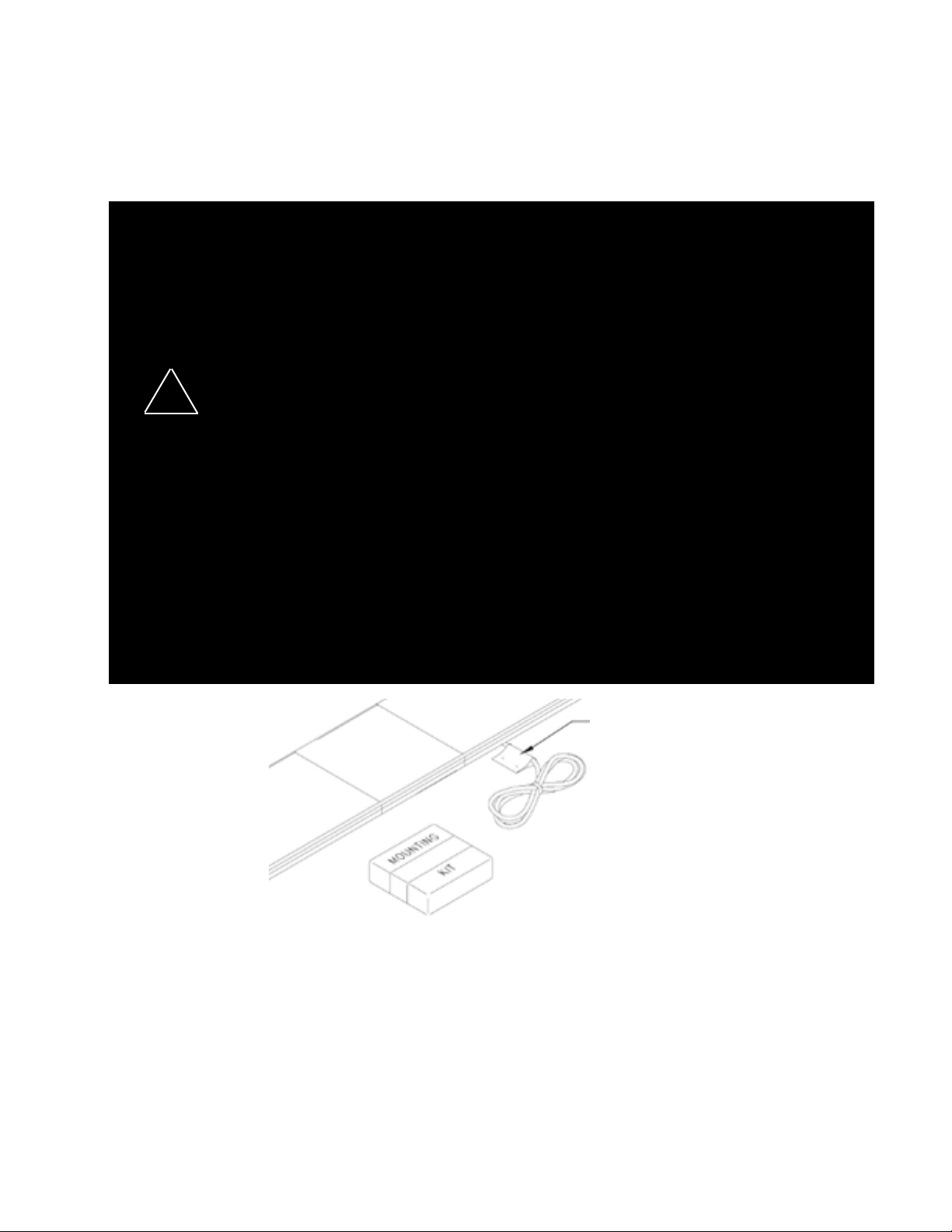
Mounting Hardware
All mounting hardware is packed in a small box inside the main carton. Four standard kits are available: (1) Hook-On Type,
(1) Tow and Recovery and (2) Permanent Types. These are discussed in detail later. Note: Hook-on mounting for "gutterless" type vehicles will require a special hook for mounting. Several special application hooks are available. Contact the
factory for details.
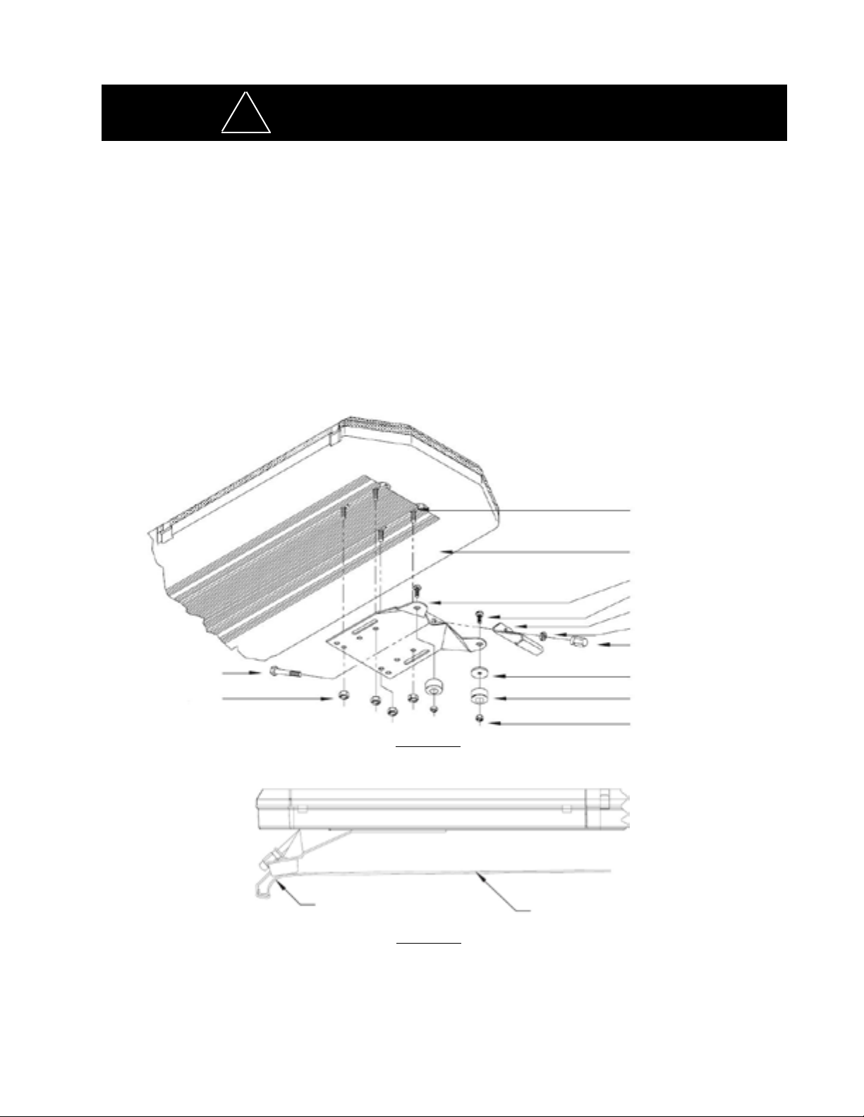
Hook-on Mounting
Begin the installation by attaching the rubber feet to the mounting brackets using the black 1/4" carriage bolts and 1/4" nuts
provided. See Figure 1. (Do not install shims at this time). Place the light bar upside down on a table or other work surface,
being careful not to scratch the lenses. Slide the 5/16" carriage bolts into the frame. Secure the mounting brackets nger
tight so they support the weight of the light bar, but can still be positioned. Locate the vehicle on a level surface. Place the
light bar on the roof of the vehicle. Place a soft pad in the center of the roof to protect the paint. The mounting brackets
must be placed so that the rubber feet are resting on the curved section of the roof, see Figure 2. This is the strongest part
of the roof. Once the light bar is centered, tighten the mounting bracket to the light bar. Using a tape measure and a level,
center the light bar from side to side and locate a position on the roof where the light bar is level.
improper number of screws may result in loss of warranty coverage on the
equipment.
5/16" Cap Screw
5/16" Nut
Curved Feet on
Curved Portion
FIGURE 1
Vehicle Gutter
5/16-18 Carriage Bolt
Bottom of Lightbar
Mounting Bracket
1/4-20 Carriage Bolt
Gutter Hook
5/16" Split Lockwasher
5/16" Trim Nut
(Do Not Overtighten)
Plastic Shim (if needed)
Rubber Foot
1/4" Acorn Nut
Vehicle Roof
FIGURE 2
The shims provided may be used here to help level the light bar, see Figure 1. Also, the tabs on the mounting brackets may
be bent at any angle to match the curvature of the roof. Select the appropriate length cap screw and insert through the holes
in the gutter hook and mounting bracket, and into a lock washer and acorn nut as shown in Figure 1. If a special hook for a
"gutterless" vehicle is used, refer to the instructions for that hook at this time. The stainless steel cap screws supplied are
sized for the most common installations, but longer and
the cap screws on both sides evenly keeping the light bar centered and level.
shorter bolts are available at any hardware store. Tighten
3
Page 4
NOTE: Tighten only until the bar is secure (bar does not move when bumped sharply with the heel of the palm). It is NOT
necessary to dimple the roof to obtain a stable attachment. If the light bar "bows" more than 3/16" (determined by placing
a straightedge along the front, bottom part of the frame and measuring downward at the center of the frame), loosen the
5/16" trim nut sightly.
Re-Installation: When moving a light bar from one vehicle to another, we suggest that new rubber feet be used. These are
standard hardware items, and can usually be found at any hardware store, or can be ordered from the factory. The special
hooks are stainless steel and should be saved and reused. Mounting kit parts are available to permit remounting on vehicles
of different design or make. Consult your local dealer or Code 3 , Inc. for detailed information.
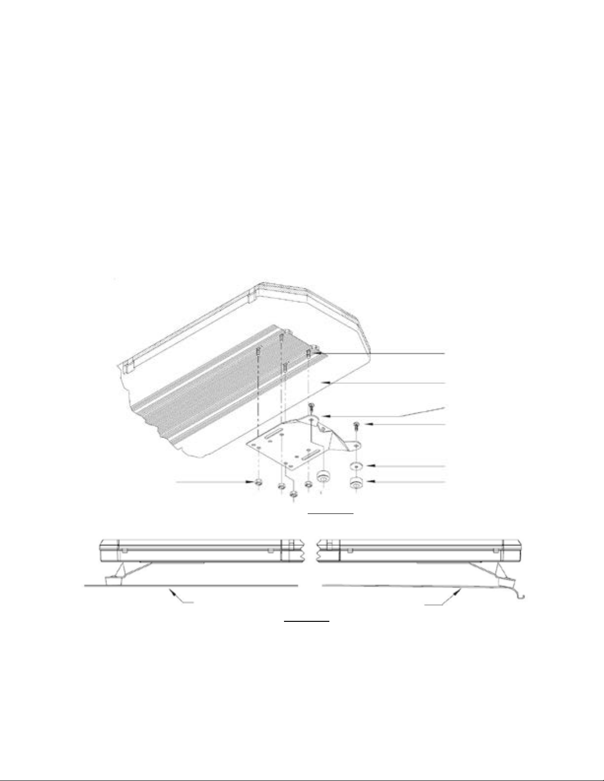
Permanent Mounting
Typical Mounting: Refer to Figure 3. Place the light bar upside down on a table or other work surface, being careful not to
scratch the lenses. Slide the 5/16" carriage bolts into the frame. Secure the mounting brackets nger tight so they support
the weight of the light bar. Place the unit on the roof of the vehicle. Place a soft pad in the center of the roof to protect the
paint. The mounting brackets must be placed so that they are resting on the curved section of the roof, see Figure 4. This
is the strongest part of the roof. Once the light bar is centered, tighten mounting brackets to light bar. Using a tape measure
and a level, center the light bar from side
shims provided may be used here to help level the light bar. Also, the tabs on the mounting bracket may be
bent at any angle to match the curvature of the roof (see Figure 4).
to side and locate a position of the roof where the light bar is level. The
5/16" Nut
Flat Roof
FIGURE 3
FIGURE 4
Curved Roof
5/16-18 Carriage Bolt
Bottom of Lightbar
Mounting Bracket
Customer Supplied
Bolt
Plastic Shim (if
needed)
Rubber Foot
Place Feet on
Curved Portion
Once the light bar is level and centered, mark the holes through the mounting tabs and remove the light bar from the vehicle.
Make sure that the drill will not damage anything when penetrating the roof. Drill the mounting holes and remove any burrs.
Attachment can be made using 1/4" cap screws, toggle bolts, or other fasteners as may be convenient. Use sealant as
necessary to prevent water leakage into the vehicle.
4
Page 5

Wiring Instructions
Before attempting to connect wiring refer to wire tag attached to the lightbar's main cable. Each wire in the cable controls
a separate lightbar function as described in the wire tag.
Larger wires and tight connections will provide longer service life for components. For high
current wires it is highly recommended that terminal blocks or soldered connections be used
with shrink tubing to protect the connections. Do not use insulation displacement connectors
(e.g. 3M® Scotchlock type connectors). Route wiring using grommets and sealant when passing through compartment walls. Minimize the number of splices to reduce voltage drop. High
ambient temperatures (e.g. underhood) will signicantly reduce the current carrying capacity of
wires, fuses, and circuit breakers. Use "SXL" type wire in engine compartment. All wiring should
conform to the minimum wire size and other recommendations of the manufacturer and be pro-
!
WARNING!
tected from moving parts and hot surfaces. Looms, grommets, cable ties, and similar installation
hardware should be used to anchor and protect all wiring. Fuses or circuit breakers should be
located as close to the power takeoff points as possible and properly sized to protect the wiring
and devices. Particular attention should be paid to the location and method of making electrical
connections and splices to protect these points from corrosion and loss of conductivity. Ground
terminations should only be made to substantial chassis components, preferably directly to the
vehicle battery. The user should install a fuse sized to approximately 125% of the maximum Amp
capacity in the supply line to protect against short circuits. For example, a 30 Amp fuse should
carry a maximum of 24 Amps. DO NOT USE 1/4" DIAMETER GLASS FUSES AS THEY ARE
NOT SUITABLE FOR CONTINUOUS DUTY IN SIZES ABOVE 15 AMPS. Circuit breakers are
very sensitive to high temperatures and will "false trip" when mounted in hot environments or
operated close to their capacity.
Routing
The only signicant difference between the 21IF™ with optional ArrowStik® and a conventional 21IF™ is the additional,
thinner cable exiting the bottom of the lightbar. The larger cable is the lightbar power cable. Route the wiring cable into
the engine or passenger compartment, taking care to use grommets and to apply sealant around openings to keep water
out. It is advisable to leave an extra loop of cable when installing the light bar to allow for future changes or reinstallations.
Connect the black lead to a solid frame ground (earth), preferably, the (-) or ground (earth) side of the battery and bring the
other wires to the control head or switches. Connect the wires as directed by the wiring instructions on the cable.
Arrowstik® / Narrowstik®
OPTIONAL L.E.D. NARROWSTIK® (11-wire) WIRING AND CONTROL HEAD INSTALLATION - After installation of the
lightbar, route the smaller of the two power cables through the vehicle to the location chosen for the control head. Cut the
cable to length and strip back the outer insulation to expose the seven or eleven colored wires. Strip back 1/8” - 1/4” of
colored insulation from each of the wires in the cable. Connect these wires to the seven position / eleven position terminal
plug enclosed in the user parts bag, according to the diagram on the bottom of the control head.
Refer to the control head manual packaged with the lightbar for control head installation
and operation instruction.
5
Page 6

L.E.D. Fusing Considerations
00
1
1
2
9
9
9 9
21
LOC
LOC
LOC
9
9
9 9
121
2
3
The average current draw per light engine assembly is very low; however, the instantaneous peak current to a module can
be signicantly higher during low voltage conditions. To avoid prematurely blowing ATO style fuses or tripping breakers it is
recommended the following rule-of-thumb be used to size fuses or breakers. This is especially important in lightbars with
many LED modules (light engine assemblies) running off a single fused source.
Minimum fuse size calculation is as follows:
Multiply the total number of light engine assemblies by 1.5. For example, a light bar with 18 light heads would
require a single 27A fuse, minimum (18 x 1.5 = 27).
WARNING!
!
This Product contains high intensity LED devices. To prevent eye damage, DO NOT stare into light beam at close range.
Setting Flash Patterns (TorusTM with Independent Flashing Lightheads)
Flash Pattern Description
1. Cycle Flash (DEFAULT)--------------Cycles through various patterns @ 70 fpm
2. NFPA Quad Flash 80 FPM-----------Four Pulses per ash @ 80 fpm
3. Quad Flash 70 FPM--------------------Four Pulses per ash @ 70 fpm
4. Steadyburn-------------------------------Steady-Burn
5. Five Flash 70 FPM---------------------Five Pulses per ash @ 70 fpm
6. Triple Flash 70 FPM ------------------Three Pulses per ash @ 70 fpm
7. Double Flash 70 FPM-----------------Two Pulses per ash @ 70 fpm
8. Single Flash 70 FPM------------------One Pulse per ash @ 70 fpm
9. Quad Pop Flash 70 FPM-------------Four Pulses per ash ( 3 equal, 1 extended) @ 70 fpm
10. Triple Pop Flash 70 FPM------------Three Pulses per ash ( 2 equal, 1 extended) @ 70 fpm
11. Mod Flash
12. Cycle Flash 150 FPM-----------------Cycles through various patterns @ 150 fpm
13. Five Flash 150 FPM-------------------Five Pulses per ash @ 150 fpm
14. Quad Flash 150 FPM-----------------Four Pulses per ash @ 150 fpm
15. Triple Flash 150 FPM ----------------Three Pulses per ash @ 150 fpm
16. Double Flash 150 FPM---------------Two Pulses per ash @ 150 fpm
17. Single Flash 150 FPM----------------One Pulse per ash @ 150 fpm
18. Single Flash 250 FPM----------------One Pulse per ash @ 250 fpm
19. Single Flash 375 FPM----------------One Pulse per ash @ 375 fpm
The ash pattern can be changed by shorting the JP1 pins with a wire or blade of a screwdriver (shown below). The lighthead can be reset to the default by shorting the JP1 pins for greater than 5 seconds and then releasing.
Momentarily short and release to change patterns
Optic removed for clarity
6
Located on front of
Integrated PCB/Light Engine
Page 7

Take Down and Alley Lights
Alley Lights
Located at the ends of the light bar to provide light to the side of the vehicle.
Stationary Lamps/Takedown Lights
A stationary assembly used for ArrowStik ashing, takedown, and/or work light applications.
The lamps used for either application are either MR11 Halogen or LED. Reference Figure 5.
MR-11 (Halogen)
LED
FIGURE 5
7
Page 8

Maintenance
Lens Cleaning
Use plain water and a soft cloth, or Code 3® lens polish and a very
soft paper towel or facial tissue. Because plastic scratches easily,
cleaning is recommended only when necessary (about every
six months). Do not subject the lenses to car washes that use
brushes, as these will scratch the lenses.
Twist to
Lift Lens
Pry
Up to
Remove
Lens
Clip
Lens Removal
First, disengage the lens clips (4 per lens) as shown in Figure 6.
Finally, insert a screwdriver into the small slot in the lens clip pocket or
the lens edge, and twist the screwdriver to lift the lens.
FIGURE 6
Light Head Removal and/or Lamp Replacement
Directional/Corner: Remove single screw securing the light head assembly to the at plate, lift light head assembly, and
then remove the control wire. Reference Figure 7.
LED TD/Alley: Remove the single screw securing the light head assembly to the at plate, lift light head assembly, and
then disconnect the red wire from the control wire by decoupling the quick slides (make sure to pull on the quickslides
only, not the wires). Reference Figure 7.
MR11 Halogen TD/Alley: Remove the two screws securing the light head assembly to the at plate, lift light head assembly, and then disconnect the red wire from the control wire by decoupling the quick slides (make sure to pull on the
quickslides only, not the wires). Remove the lamp assembly by removing the appropriate fasteners, remove fasteners
sandwiching MR11 in bracket, and remove lamp. Replace the lamp and reassemble. Reference Figure 7.
LED TD/Alley
Module
Corner
Module
Directional
Module
Light Head Modules
MR11 Halogen
FIGURE 7
8
Page 9

Parts List & Exploded View
(Reference numbers identify items shown in Figure 8)
Ref No. Description Part No.
1 Bottom Outboard Lens - Clear T02361
2 Bottom Center Lens - Clear T02371
3 Outboard Lens Cap
Clear T03271
Red T03272
Blue T03273
Amber T03274
Black T03278
4 Center Lens Cap
Clear T03281
Red T03282
Blue T03283
Amber T03284
Black T03288
5 4LED Directional Module
6 6LED Corner Module
7 3LED Takedown/Alley Module
8 3LED Directional Module
Call Factory
3
1
Troubleshooting
5
4
8
7
2
3
6
1
7
FIGURE 8
All lightbars are thoroughly tested prior to shipment. However, should you encounter a problem during installation or during the life of the product, follow the guide below for information on repair and troubleshooting. Additional information may
be obtained from the factory technical help line at 314-996-2800.
9
Page 10

Notes
10
Page 11

Notes
11
Page 12

WARRANTY
Code 3®, Inc.’s emergency devices are tested and found to be operational at the time
of manufacture. Provided they are installed and operated in accordance with manufacturer’s
recommendations, Code 3®, Inc. guarantees all parts and components except the lamps to a period
of 1 year, LED Lighthead modules to a period of 5 years (unless otherwise expressed) from the date of
purchase or delivery, whichever is later. Units demonstrated to be defective within the warranty period
will be repaired or replaced at the factory service center at no cost.
Use of lamp or other electrical load of a wattage higher than installed or recommended by
the factory, or use of inappropriate or inadequate wiring or circuit protection causes this warranty to
become void. Failure or destruction of the product resulting from abuse or unusual use and/or accidents
is not covered by this warranty. Code 3®, Inc. shall in no way be liable for other damages including
consequential, indirect or special damages whether loss is due to negligence or breach of warranty.
CODE 3®, INC. MAKES NO OTHER EXPRESS OR IMPLIED WARRANTY INCLUDING,
WITHOUT LIMITATION, WARRANTIES OF FITNESS OR MERCHANTABILITY, WITH RESPECT TO
THIS PRODUCT.
PRODUCT RETURNS
If a product must be returned for repair or replacement*, please contact our factory to obtain a Return
Goods Authorization Number (RGA number) before you ship the product to Code 3®, Inc. Write the
RGA number clearly on the package near the mailing label. Be sure you use sufcient packing materials
to avoid damage to the product being returned while in transit.
*Code 3®, Inc. reserves the right to repair or replace at its discretion. Code 3®, Inc. assumes no
responsibility or liability for expenses incurred for the removal and /or reinstallation of products requiring
service and/or repair.; nor for the packaging, handling, and shipping: nor for the handling of products
returned to sender after the service has been rendered.
Problems or Questions? Call The Technical Assistance HOTLINE - (314) 996-2800
Code 3, Inc.
10986 N. Warson Road
St. Louis, Missouri 63114-2029—USA
Ph. (314) 426-2700 Fax (314) 426-1337
www.code3pse.com
Code 3,® Inc., a subsidiary of
Public Safety Equipment, Inc.
Code 3 is a registered trademark of
Code 3, Inc.
Revision 0, 09/12 - Instruction Book Part No. T52265
©2012 Public Safety Equipment, Inc. Printed in USA
12
 Loading...