

Page 1
INSTALLATION &
UTILITY INTERCEPTOR SHOWN:
OPERATION
MANUAL
2011 FORD EXPLORER &
2012-13 Uitility Interceptor
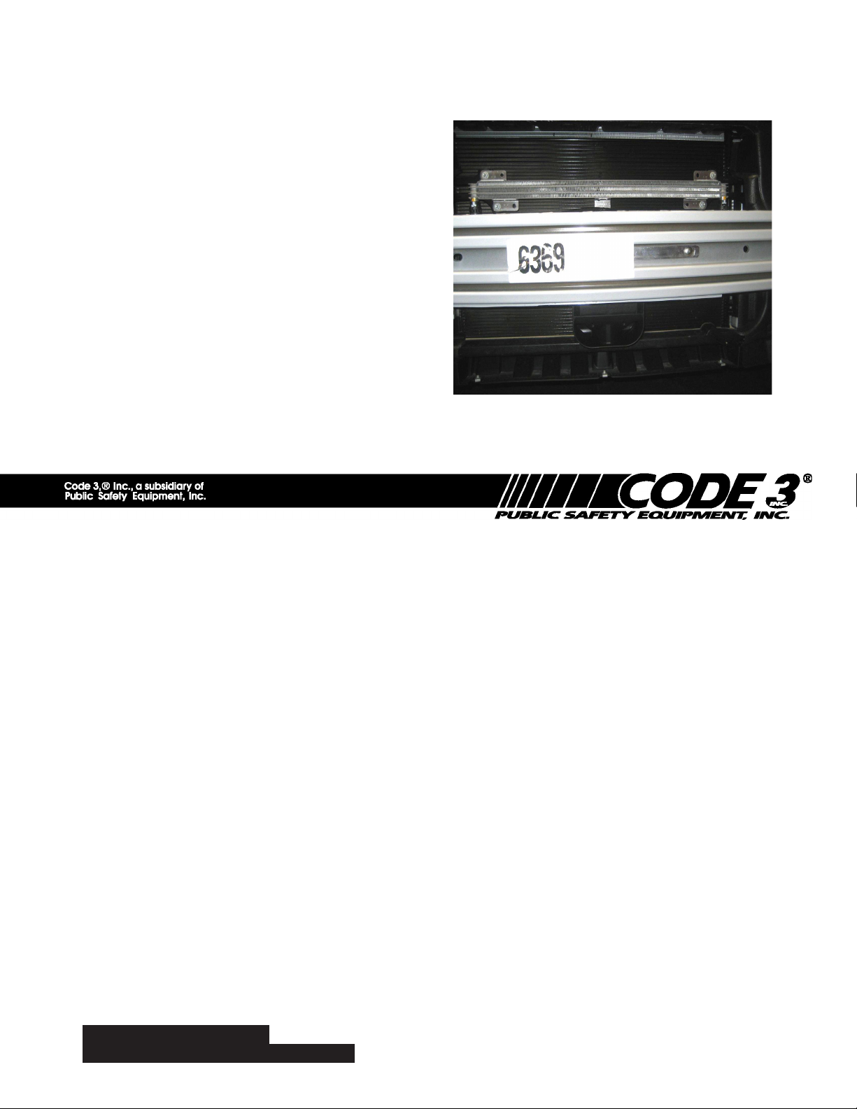
Speaker Bracket
Position : Below bumper installation shown,
Installation does not interfer with auxiliary cooler on Utility Interceptor version of Explorer.
2011-13 FORD EXPLORER & UTILITY INTERCEPTOR
SPEAKER INSTALLATION
Table of Contents:
Page No: Description:
1. Preparation for installation
2. Bolt-On Easy Installation of speaker to vehicle bumper system
3. Reinstalling the vehicle facia, Wiring connections and
Installation notes
4. Warranty Information
Preparation for Installation:
1. Access to the rear and front of the bumper extrusion is required in order to complete
hardware installation and make wiring connections.
Remove top engine shroud cover (2 push in fasteners & 6 hex head screws)•
Remove phillips head screws from both front wheel well forward areas•
Remove hex head screws from lower facia behind air dam area of vehicle•
Remove (2) phillips head screws from DS & PS facia under front wheel well trim •
Remove facia & grill from vehicle & unplug fog light connectors DS & PS•
IMPORTANT:
Read all instructions and warnings before installing and using.
This manual must be delivered to the end user of this equipment.
INSTALLER:
1
Page 2
NOTE: While vehicle facia is removed, installation of grill light brackets, Par
36 LED lighthead brackets and wiring harnesses may be easily accomplished.
Bolt - On Installation of Speaker Bracket to bumper system on vehicle:
(No Drilling Necessary)
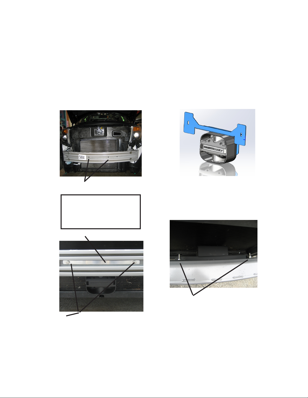
DOMESTIC EXPLORER SHOWN:
1. removal of the front facia
exposes the bumper area for
speaker installation. Locate (2)
center holes in the mid section
retaining strap bracket
carriage bolts
3. install 4.5" stainless steel carriage bolts through retaining strap
bracket, (Included in kit), and
place through holes in center of
bumper.
4. place speaker bracket over bolt
ends with speaker facing forward
g1
g3
Below
bumper
install
shown.
(FRONT VIEW)
NOTE:
Speaker should sit above lower lip of radiator hous-
ingandawayfromthefrontoftheradiatorns.
No contact with the radiator should be alowed.
g2
2. install speaker onto bracket using the
hardware provided. Speaker should sit in-
sidebracketrecessasshowning.2.
g4
(TOP VIEW)
5.installatwasher,lockwasherandnuton
the back side of the speaker bracket.
6. slide bracket up in mounting slots and
tighten nuts using wrench.
2
Page 3

Re-installation of vehicle facia:
1. Pre-determine wiring connections for speaker to wiring harness prior to re-installation of
vehicle facia.
2. Place vehicle facia into place and set top engine shroud over top edge of facia.
3. Place (2) plastic push-in fasteners through top engine shroud to hold it in place.
4. Hand insert and start one hex head fastener on each end of top engine shroud and through
the top leading edge of front facia. (These will hole facia in place for further installation)
5. Lift the wheel well trim cover and place facia into edges around each headlight and snap
trailing edge of facia into groove around front wheel well. The facia will snap into place on
each side of the vehicle at this point.
6. Re-install phillips head screws into sides of front facia and around each wheel well.
7. Re-install hex head screws along underside of facia behind air dam of lower facia.
WIRING CONNECTIONS:
Extend the BLUE (Positive) and the WHITE (Negative) speaker wires to your siren
amplier and connect as shown in the ampliers instructions and test the siren for proper
operation.
Notes:
3
Page 4

Larger wires and tight connections will provide longer service life for components. For high current wires it is highly
recommended that terminal blocks or soldered connections be used with shrink tubing to protect the connections. Do
not use insulation displacement connectors (e.g. 3M® Scotchlock type connectors). Route wiring using grommets
WARNING!
and sealant when passing through compartment walls. Minimize the number of splices to reduce voltage drop. High
ambient temperatures (e.g. underhood) will signicantly reduce the current carrying capacity of wires, fuses, and circuit
breakers. Use "SXL" type wire in engine compartment. All wiring should conform to the minimum wire size and other
recommendations of the manufacturer and be protected from moving parts and hot surfaces. Looms, grommets,
cable ties, and similar installation hardware should be used to anchor and protect all wiring. Fuses or circuit breakers
should be located as close to the power takeoff points as possible and properly sized to protect the wiring and devices.
Particular attention should be paid to the location and method of making electrical connections and splices to protect
these points from corrosion and loss of conductivity. Ground terminations should only be made to substantial chassis
components, preferably directly to the vehicle battery. The user should install a fuse sized to approximately 125% of
the maximum Amp capacity in the supply line to protect against short circuits. For example, a 30 Amp fuse should
carry a maximum of 24 Amps. DO NOT USE 1/4" DIAMETER GLASS FUSES AS THEY ARE NOT SUITABLE FOR
CONTINUOUS DUTY IN SIZES ABOVE 15 AMPS. Circuit breakers are very sensitive to high temperatures and will
"false trip" when mounted in hot environments or operated close to their capacity.
Wear hearing protection when testin, Use siren only for emergency response, Roll up windows when siren is operating,
Avoid exposure to the siren sound outside of vehicle.
WARRANTY
Code 3, ®Inc.'s emergency devices are tested and found to be operational at the time of manufacture. Provided they are installed and
operated in accordance with manufacturer's recommendations, Code 3, Inc. guarantees all parts and components except the lamps to a period
of 1 year (unless otherwise expressed) from the date of purchase or delivery, whichever is later. Units demonstrated to be defective within the
warranty period will be repaired or replaced at the factory service center at no cost.
Use of lamp or other electrical load of a wattage higher than installed or recommended by the factory, or use of inappropriate or inadequate
wiring or circuit protection causes this warranty to become void. Failure or destruction of the product resulting from abuse or unusual use and/or
accidents is not covered by this warranty. Code 3, Inc. shall in no way be liable for other damages including consequential, indirect or special
damages whether loss is due to negligence or breach of warranty.
CODE 3, INC. MAKES NO OTHER EXPRESS OR IMPLIED WARRANTY INCLUDING, WITHOUT LIMITATION, WARRANTIES OF
FITNESS OR MERCHANTABILITY, WITH RESPECT TO THIS PRODUCT.
PRODUCT RETURNS
If a product must be returned for repair or replacement*, please contact our factory to obtain a Return Goods Authorization Number
(RGA number) before you ship the product to Code 3, Inc. Write the RGA number clearly on the package near the mailing label. Be sure you
use sufcient packing materials to avoid damage to the product being returned while in transit.
*Code 3, Inc. reserves the right to repair or replace at its discretion. Code 3, Inc. assumes no responsibility or liability for expenses incurred for the removal and /or reinstallation of products requiring
service and/or repair.; nor for the packaging, handling, and shipping: nor for the handling of products return to sender after the service has been rendered.
PROBLEMS OR QUESTIONS? CALL OUR TECHNICAL ASSISTANCE HOTLINE (314) 996-2800
WWW.CODE3PSE.COM
Code 3® is a registered trademark of Code 3, Inc., a subsidiary of Public Safety Equipment, Inc.
4
Code 3®, Inc.
St. Louis, Missouri 63114-2029—USA
Ph. (314) 426-2700 Fax (314) 426-1337
10986 N. Warson Road
Part No. T56540 Rev. 2 06/2012
©2005 Code 3, Inc
 Loading...