

Page 1
INSTALLATION
MANUAL
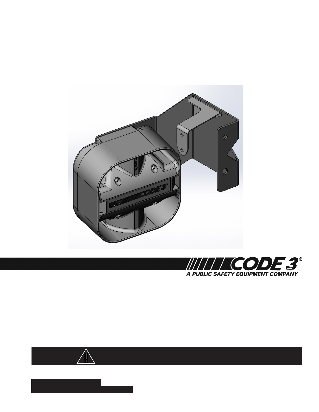
C3100 PASSENGER SIDE SPEAKER
MOUNTING BRACKET
2005 - PRESENT IMPALA PPV
WARNING!
For future reference record your product's serial no. here __________________________________________
IMPORTANT:
CONTENTS:
Installation & Mounting.........................................................2-4
Parts List...............................................................................5
Notes:...................................................................................6-7
Warranty................................................................................8
Utilizing non-factory supplied screws and/or mounting brackets and/or the improper number of
screws may result in loss of warranty coverage on the equipment.
Read all instructions and warnings before installing and using.
This manual must be delivered to the end user of this equipment.
INSTALLER:
Page 2
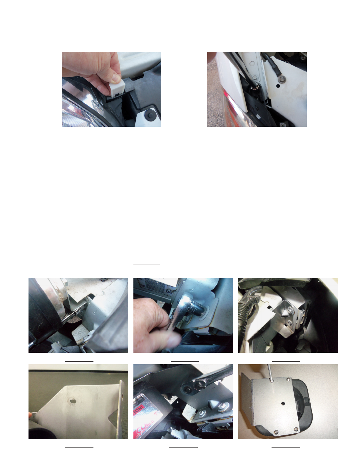
Installation Instructions:
Step 1. Remove the passenger side head light by pulling up and removing the white plastic retention clip (See Figure
-1). Remove the single mounting screw at the passenger side fender using a 7 mm hex socket wrench (See Figure -2).
Pull the head light out, unplug the wiring connector & set the head light, clip, & mounting screw aside.
FIGURE -1 FIGURE -2
Step 2. Remove the OEM horn assembly mounting screw with a 10 mm hex socket (See Figure -3). Take note as to
which horn is the top horn and which is the bottom. Unplug the horn connector and set the horn assembly aside.
Tuck the head light & horn wires & their connectors back in the fender to provide more room to install the speaker.
Step 3. Remove the (2) Vehicle bumper bolts using a 13 mm socket (See Figure -4).
Step 4. Position the Speaker Mounting bracket inside the side of the vehicle's frame as shown in Figure -5 and locate
the existing hole in the side of the vehicle's frame which will be behind the slot in the Speaker Mounting Bracket shown
in Figure -6. Note: The hole in the vehicle's frame is covered up by a bar code sticker. Take a small Phillips screw
driver or punch and poke a hole through the bar code sticker. Once you have located the existing hole in the vehicle's
frame, using a 10 mm socket, thread the supplied 1/4" X 5/8" Long Slot/Hex head sheet metal screw into the hole in the
side of the vehicle's frame (See Figure -7 -Shown with Speaker Mounting Bracket in place for clarity only) until the
screw has created a thread in the vehicle's frame sheet metal. Thread the screw in until it is almost bottomed out but not
fully tightened. Remove the screw for later steps in the process.
Step 5. Attach the C3100 Speaker to the mounting bracket using the (4) supplied #12 Phillips Pan Head Screws with (4)
1/4" internal tooth star washers (See Figure 8). NOTE: The speaker must be oriented with the speaker wires exit-
ing the bottom of the speaker and the CAUTION label at the top (See Figure -9 on page 3). The exit holes for the
wires are also the speaker drain holes. Failure to mount the speaker in this orientation will void all warranties!
FIGURE -3 FIGURE -4 FIGURE -5
FIGURE -6 FIGURE -7 FIGURE -8
2
Page 3
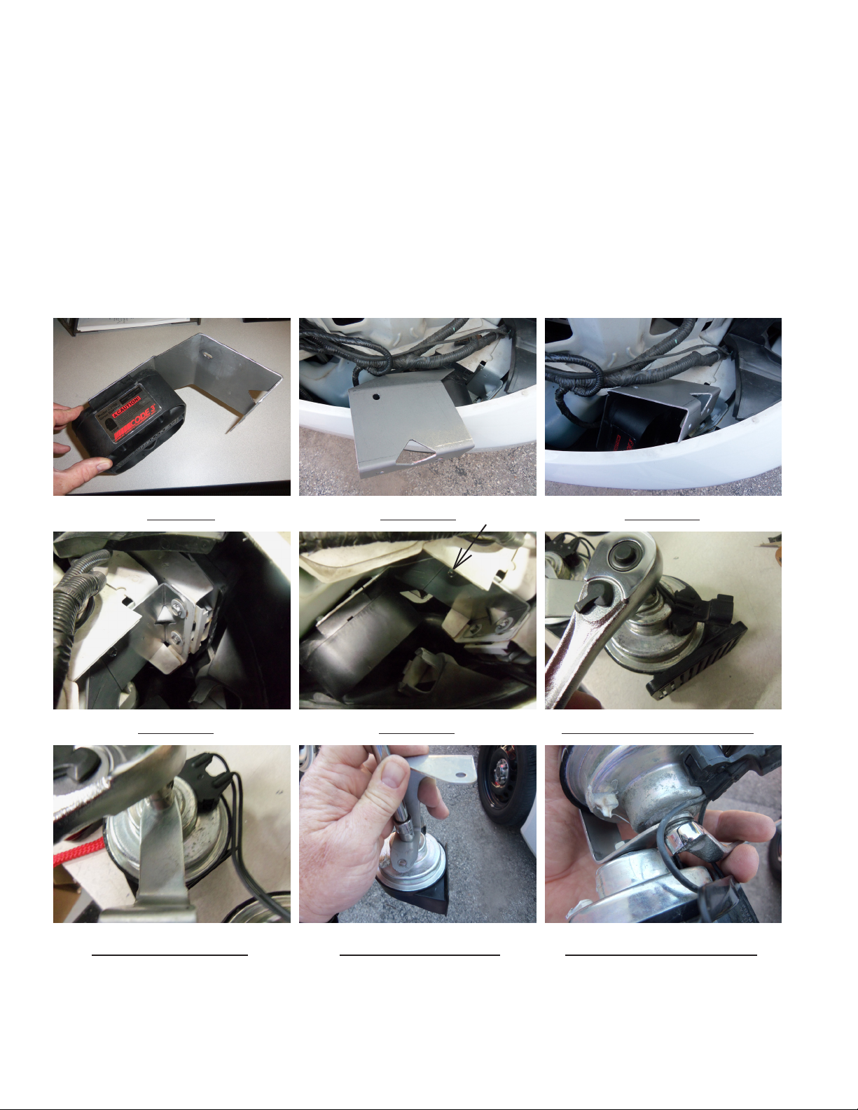
Installation Instructions - Cont:
Step 6. Drop the speaker assembly into the headlight cavity (See Figure -10) then rotate the speaker bracket mounting
ange forward & down into the headlight cavity while lowering the speaker deeper into the space below the headlight
(See Figure -11). NOTE: The vehicle's exible plastic front shroud and it's parts below will ex out of the way to
allow the speaker assembly to drop into position. Space is tight but it will t!
Step 7. Once the bracket is in position, thread the bumper bolts back into their holes (see Figure -12). Lift up on the
speaker and thread the supplied 1/4" X 5/8" Long Slot/Hex head sheet metal screw through the slot in the Speaker
Mounting Bracket and into the hole in the side of the vehicle's frame (See Arrow in Figure -13).
Step 8. Tighten up the bumper bolts and remove the 1/4" X 5/8" Long Slot/Hex head screw for the next step.
Step 9. Again take note and keep track of which horn is the bottom and which is the top, remove the hex nuts fastening
the horns to the vehicle's OEM horn mounting bracket (See Figures 14 & 15). Discard the OEM horn bracket. Mount
the horns to the supplied Horn Relocation/Mounting Bracket as shown in Figure -16 (Attach the TOP HORN rst) &
Figure -17 (BOTTOM HORN). Only tighten the horn fastening nuts nger tight at this time so they can be adjusted later.
FIGURE -9 FIGURE -10 FIGURE -11
FIGURE -12 FIGURE -13 FIGURE -14 - BOTTOM HORN
FIGURE 15 - TOP HORN FIGURE -16 - TOP HORN FIGURE -17 - BOTTOM HORN
3
Page 4
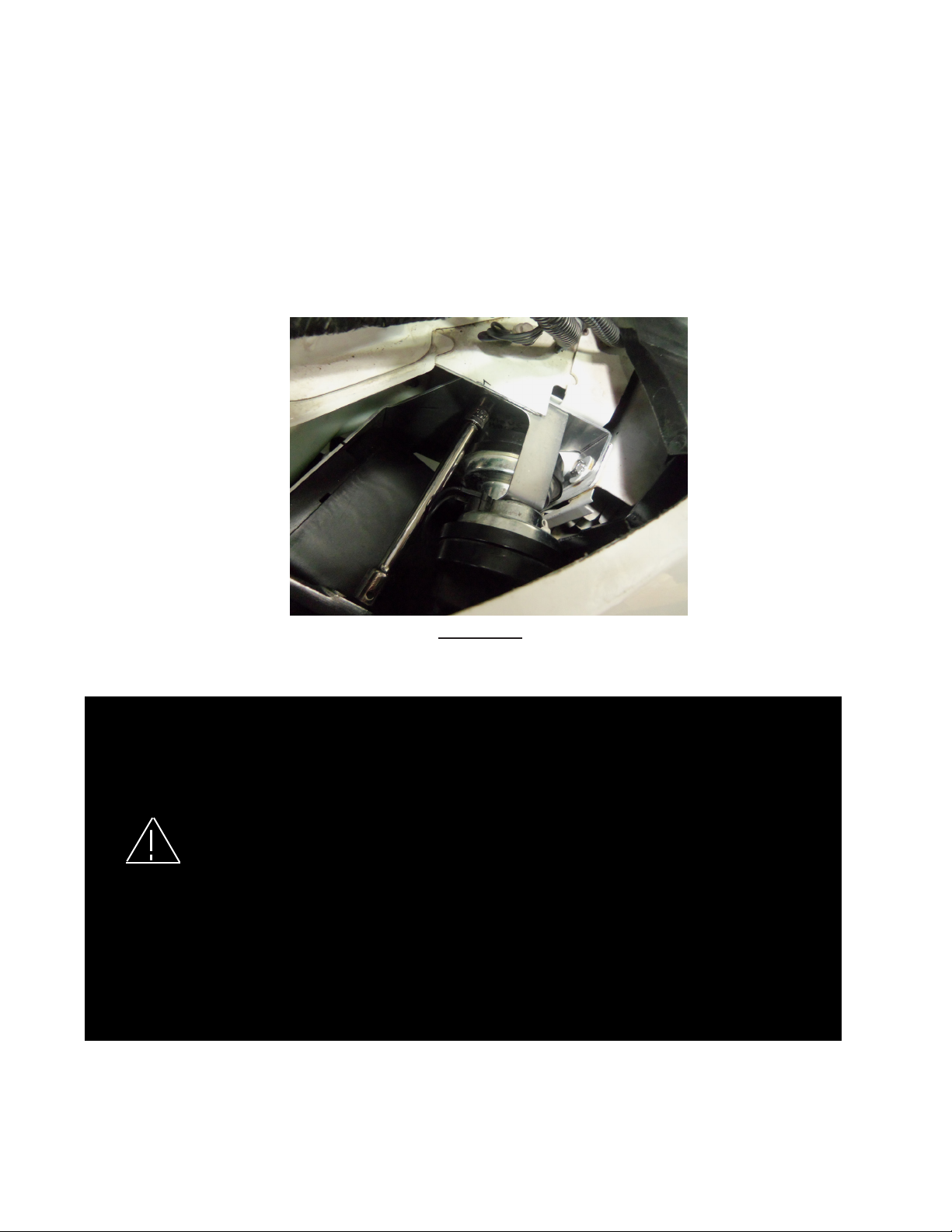
Installation Instructions - Cont:
Step 10. Reconnect the wiring connector to the bottom horn. Position the New Horn Assembly with both horn ares
facing down as shown in Figure -18. Thread the supplied 1/4" X 5/8" Long Slot/Hex head sheet metal screw with a supplied 1/4" internal tooth star washer through the mounting hole in the Horn Relocation/Mounting Bracket and into the
threaded hole in the vehicle's frame from Step -4. Tighten the screw using a 10 mm socket making sure that the top of
the Horn Relocation/Mounting Bracket is up against the under side of the vehicle's frame ange (see Figure -18). Position the horns so that they aim down and slightly to the rear of the vehicle and tighten the horn retention nuts to secure
the horns in place. Note: The top and bottom horns should not be touching each other or anything around them.
Step 11. Route the speaker wires as desired. Connect the speaker leads to the siren according to the siren install
manual.
Step 12. Re install the vehicle's head light.
FIGURE -18
Larger wires and tight connections will provide longer service life for components. For high current wires it
is highly recommended that terminal blocks or soldered connections be used with shrink tubing to protect
the connections. Do not use insulation displacement connectors (e.g. 3M® Scotchlock type connectors).
Route wiring using grommets and sealant when passing through compartment walls. Minimize the
number of splices to reduce voltage drop. High ambient temperatures (e.g. under hood) will signicantly
reduce the current carrying capacity of wires, fuses, and circuit breakers. Use "SXL" type wire in engine
compartment. All wiring should conform to the minimum wire size and other recommendations of the
manufacturer and be protected from moving parts and hot surfaces. Looms, grommets, cable ties, and
similar installation hardware should be used to anchor and protect all wiring. Fuses or circuit breakers
WARNING!
should be located as close to the power takeoff points as possible and properly sized to protect the wiring
and devices. Particular attention should be paid to the location and method of making electrical connections
and splices to protect these points from corrosion and loss of conductivity. Ground terminations should
only be made to substantial chassis components, preferably directly to the vehicle battery. The user should
install a fuse sized to approximately 125% of the maximum Amp capacity in the supply line to protect
against short circuits. For example, a 30 Amp fuse should carry a maximum of 24 Amps. DO NOT USE
1/4" DIAMETER GLASS FUSES AS THEY ARE NOT SUITABLE FOR CONTINUOUS DUTY IN SIZES
ABOVE 15 AMPS. Circuit breakers are very sensitive to high temperatures and will "false trip" when
mounted in hot environments or operated close to their capacity.
4
Page 5

PARTS LIST:
6
5
1
5
4
4
2
3
Item No Part Description Qty: Part Number
1 C3100 Speaker Mounting Bracket-Passenger Side 2005+Impala 1 T17154
2 C3100 Speaker Assembly 1 S71684
3 Horn Relocation/Mounting Bracket 1 T17155
4 1/4" X 5/8" Long Slot Hex Washer Head SMS STL Zinc 1 T16222
5 1/4" Internal Tooth Star Washer 5 T11253
6 #12 X 1" Long Phillips Pan Head SMS - 18-8 SS 4 T11247
5
Page 6

NOTES:
6
Page 7

NOTES:
7
Page 8

WARRANTY
This product was tested and found to be operational at the time of manufacture. Provided this product
is installed and operated in accordance with the manufacturer's recommendations, CODE 3, Inc. guarantees
this product for a period of 5 years from the date of purchase or delivery, whichever is later (does not apply to
lamps). Units demonstrated to be defective within the warranty period will be repaired or replaced at the factory
service center at no cost.
Use of a lamp or other electrical load of a wattage higher than installed or recommended by the factory,
or use of inappropriate or inadequate wiring or circuit protection causes this warranty to become void. Failure
or destruction of the product resulting from abuse or unusual use and/or accidents is not covered by this warranty. Use of non-CODE 3, Inc. components and assemblies may cause damage to the system and/or personal
injury, and voids all warranties.
CODE 3, Inc. shall in no way be liable for other damages including consequential, indirect or special
damages whether loss is due to negligence or breach of warranty.
CODE 3, INC. MAKES NO OTHER EXPRESS OR IMPLIED WARRANTY INCLUDING, WITHOUT LIMITATION, WARRANTIES OF FITNESS OR MERCHANTABILITY, WITH RESPECT TO THIS PRODUCT.
PRODUCT RETURNS
In order to provide you with faster service, if you are going to return a product for repair or replacement*,
please contact our factory to obtain a Return Goods Authorization Number (RGA number) before you ship the
product to Code 3. Write the RGA number clearly on the package near the mailing label. Be sure you use suf-
cient packing materials to avoid damage to the product being returned while in transit.
*Code 3, Inc. reserves the right to repair or replace product at its discretion and assumes no responsibility or liability for expenses
incurred for the removal and/or reinstallation of products requiring service and/or repair.
Problems or Questions? Call our Technical Assistance HOTLINE - (314) 966-2800
10986 N. Warson Road
St. Louis, Missouri 63114-2029—USA
Ph. (314) 426-2700 Fax (314) 426-1337
www.code3pse.com
CODE 3, Inc.
Code 3 is a registered trademark of Code 3, Inc. a subsidiary of Public Safety Equipment, Inc.
Revision - 0, 08/2014 - Instruction Book Part No. T17156
8
©2014 CODE 3, Inc. Printed in USA
 Loading...