

Page 1
INSTALLATION
& OPERATION
MANUAL
PATENT PENDING
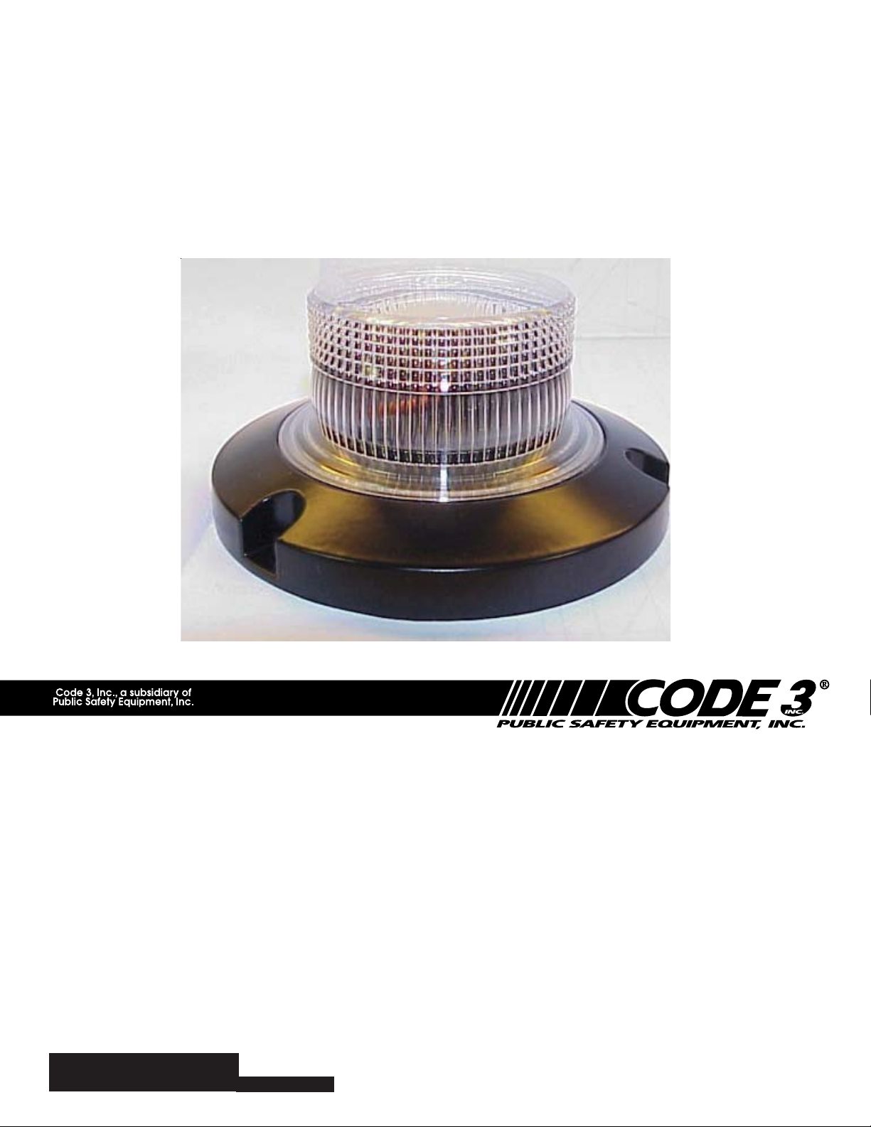
2004 LED Beacon
Contents:
Introduction (with warnings)......................................2
Installation & Mounting...........................................2-4
Features & Specifications.........................................5
Programming...............................................................5
Maintenance & Troubleshooting..............................6
Notes.............................................................................7
Warranty.......................................................................8
Read all instructions and warnings before installing and using.
IMPORT ANT:
INSTALLER:
This manual must be delivered to the end user of this equipment.
1
Page 2

Introduction
The use of this or any warning device does not insure that all drivers can or will observe or
react to an emergency warning signal. Never take the right-of-way for granted. It is your
responsibility to be sure you can proceed safely before entering an intersection, driving
against traffic, responding at a high rate of speed, or walking on or around traffic lanes.
!
WARNING!
The effectiveness of this warning device is highly dependent upon correct mounting and
wiring. Read and follow the manufacturer’s instructions before installing or using this
device. The vehicle operator should insure daily that all features of the device operate
correctly. In use, the vehicle operator should insure the projection of the warning signal is
not blocked by vehicle components (i.e.: open trunks or compartment doors), people,
vehicles, or other obstructions.
This equipment is intended for use by authorized personnel only. It is the user’s responsibility to understand and obey all laws regarding emergency warning devices. The user
should check all applicable city, state and federal laws and regulations.
Public Safety Equipment, Inc., assumes no liability for any loss resulting from the use of
this warning device.
Proper installation is vital to the performance of this warning device and the safe operation
of the emergency vehicle. It is important to recognize that the operator of the emergency
vehicle is under psychological and physiological stress caused by the emergency situation.
The warning device should be installed in such a manner as to: A) Not reduce the output
performance of the system, B) Place the controls within convenient reach of the operator
so that he can operate the system without losing eye contact with the roadway.
Emergency warning devices often require high electrical voltages and/or currents. Properly
protect and use caution around live electrical connections. Grounding or shorting of
electrical connections can cause high current arcing, which can cause personal injury and/
or severe vehicle damage, including fire. Incandescent lamps are extremely hot, allow to
cool completely before attempting to remove.
Any electronic device may create or be affected by electromagnetic interference. After
installation of any electronic device operate all equipment simultaneously to insure that
operation is free of interference. Never power emergency warning equipment from the
same circuit or share the same grounding circuit with radio communication equipment.
PROPER INSTALLATION COMBINED WITH OPERATOR TRAINING IN THE PROPER
USE OF EMERGENCY WARNING DEVICES IS ESSENTIAL TO INSURE THE SAFETY
OF EMERGENCY PERSONNEL AND THE PUBLIC.
Installation & Mounting
Wiring Instructions
The 2004 LED Beacons are designed to operate on 12-48 Volt DC negative ground
(earth) systems.
1) Route the user's wiring from the unit into the engine or passenger compartment. Use
grommets and apply sealant if needed to keep water out. Use #18 GA. or larger
wires.
2) Connect the black lead from the unit to a solid frame ground (earth), or preferably the
negative terminal of the battery.
3) Connect the red lead from the unit to one side of the user supplied control switch.
4) Connect the other terminal of the switch through a fuse or circuit breaker to the
positive terminal(+) of the battery or to the stud on the battery side of the starter
solenoid or alternator. The fuse or breaker should be rated for 10 Amps. Be aware
that circuit breakers and fuses are heat sensitive devices. Mounting them in high
temperatures may cause "false tripping". Reversing the power connections will
activate the reverse polarity protection, resulting in no light output. To correct,
properly connect the red to (+) and the black to (-) earth.
2
Page 3

5) NOTE: Crimped connectors tend to fail over time. Screw-type terminal blocks or
soldered connections provide much higher reliability.
6) The white control wire may be left unconnected. It can also be connected to GRND
through a momentary push-button switch, and be used for programming the
operation mode. Note the white wire should not be connected to a positive voltage
under any circumstances.
Permanent Mounting
Using the base as a template, mark and drill (3) holes for mounting and (1) to route the
wiring in the desired location. Check carefully before drilling to avoid damaging wiring or
other vehicle components; seal wire entry hole to prevent moisture entry and protect wires
from abrasions.
GENERAL: All devices should be mounted in accordance with the manufacturer's instructions and securely fastened to vehicle elements of sufficient strength to withstand the forces
!
WARNING!
applied to the device. Driver and/or passenger air bags (SRS) will affect the way equipment should be mounted. This device should be mounted by permanent installation and
within the zones specified by the vehicle manufacturer, if any. Any device mounted in the
deployment area of an air bag will damage or reduce the effectiveness of the air bag and
may damage or dislodge the device. Installer must be sure that this device, its mounting
hardware and electrical supply wiring does not interfere with the air bag or the SRS wiring or
sensors. Front or rear grille/bumber placement must avoid interference wih SRS sensors.
Mounting the unit inside the vehicle by a method other than the permanent installation is not
recommended as unit may become dislodged during swerving, sudden braking, or collision. Failure to follow instructions can result in personal injury.
WIRING: Larger wires and tight connections will provide longer service life for components.
For high current wires it is highly recommended that terminal blocks or soldered
connections be used with shrink tubing to protect the connections. Do not use insulation
displacement connectors (e.g. 3M
grommets and sealant when passing through compartment walls. Minimize the number of
splices to reduce voltage drop. High ambient temperatures (e.g. underhood) will
significantly reduce the current carrying capacity of wires, fuses, and circuit breakers. Use
"SXL" type wire in engine compartment. All wiring should conform to the minimum wire size
and other recommendations of the manufacturer and be protected from moving parts and
hot surfaces. Looms, grommets, cable ties, and similar installation hardware should be
used to anchor and protect all wiring.
Fuses or circuit breakers should be located as close to the power takeoff points as
possible and properly sized to protect the wiring and devices.
Particular attention should be paid to the location and method of making electrical
connections and splices to protect these points from corrosion and loss of conductivity.
Ground terminations should only be made to substantial chassis components, preferably
directly to the vehicle battery.
The user should install a fuse sized to approximately 125% of the maximum Amp capacity
in the supply line to protect against short circuits. For example, a 30 Amp fuse should
carry a maximum of 24 Amps. DO NOT USE 1/4" DIAMETER GLASS FUSES AS THEY
ARE NOT SUITABLE FOR CONTINUOUS DUTY IN SIZES ABOVE 15 AMPS. Circuit
breakers are very sensitive to high temperatures and will "false trip" when mounted in hot
environments or operated close to their capacity.
®
Scotchlock type connectors). Route wiring using
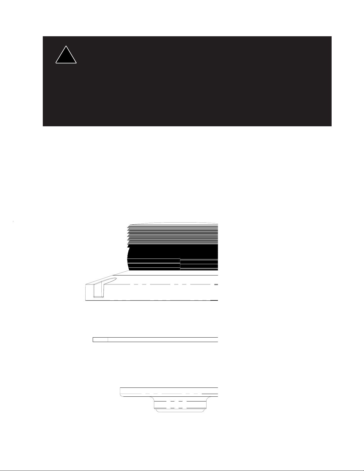
Magnetic Mounting
Attach the magnetic base to a smooth, clean, and flat surface, see Figure 1. To Operate:
Plug coil cord into a 12 or 24 Volt DC cigarette lighter; rotate and push in firmly to insure
the best possible connection.
3
Page 4
1) Rust Stains: Magnetic mounting is not intended as permanent mounting for beacons.
Long duration usage of any magnet will expose the high iron content of the steel, thereby
!
WARNING!
causing rust. The device should by removed when not used to prevent rust stains. Metallic
debris collected by the magnet will also contribute to rust stains. Insure that the magnet is
kept clean.
2) Surface rust stains can usually be removed with chrome polish, available at most auto
part stores.
3) As with any magnetically-mounted warning device, its use on the exterior of a moving
vehicle is at the sole discretion and responsibility of the user.
Magnetic mount products provide a secure, temporary installation in most circumstances
and is recommended for stationary use only. For maximum warning signal, mount the
beacon on the highest possible flat, level survace of the vehicle.
Pipe Mounting
The 2004 LED Beacon pipe mounting kit will accept a standard 1/2" NPT pipe flange
onto the beacon base. Four slotted holes are provided in the adapter plate to accomodate
the hole spacing of various pipe flanges. Attach the adapter plate to the pipe flange, then
to the beacon. Locknuts should be used to prevent the unit from working loose from the
mounting. Route the wiring as recommended and turn the beacon clockwise onto the pipe
by hand until secure. Do not over-tighten.
Figure 1
4
Page 5

Features and Specifications:
Operating Voltage: 10-48 Vdc, Reverse Polarity Protection
Flash Rate: 70 fpm minimum
Flash Modes:
1. Cycle-Flash: Cycles through Triple, Quad, Double, and Fast Single
modes at approximately 109 fpm.
2. Triple-Flash: Three consecutive pulses per flash at approximately
83 fpm.
3. Quad-Flash: Four consecutive pulses per flash at approximately
77fpm.
4. Double-Flash: Two consecutive pulses per flash at approximately
78 fpm.
5. Fast Single: Single flash pattern at 90 fpm.
6. Single-Flash: Single flash pattern at 75 fpm.
Flashing Current Draw:Single LED Beacon
Red/Amber:
.25 Avg. Amp
Blue:
.25 Avg. Amp
Flashing Current Draw:Triple LED Beacon
Red/Amber:
.75 Avg. Amp
Blue:
.75 Avg. Amp
Available colors: Red, Amber, or Blue
Size: 4.75" Dia. X 2.12" tall
Weight: 1 lb
Programming:
Programming the desired flash pattern (or operation mode) is done with the white control
wire. You can scroll through the six available flash patterns by momentarily grounding the
white control wire until you arrive at the desired operation mode. Momentary grounding of
the white wire can be accomplished either by momentarily touching the wire to GND, or
through a momentary push-button switch.
The unit will come on in the default Cycle-flash mode at the time of first power-up, until the
desired flash pattern is programmed. The default flash pattern can then be changed by
programming the desired pattern into the unit. The unit will continue to operate in the same
mode every time the unit is turned off and turned back on. The default flash pattern can be
changed at will any number of times.
The unit can be reset back to the default flash pattern (cycle-flash) by grounding the control
wire for about 8-10 seconds and then releasing it. This can be done while operating in any
of the flash modes.
5
Page 6

Maintenance:
The 2004 LED Beacons are completely sealed units designed to be maintenance free.
Refer to the guide below for help with troubleshooting. Should the unit be diagnosed as
malfunctioning, remove the unit and replace with a new module. No parts are accessible for
repair or replacement.
LED module housings may become hot with extended use. Allow modules
WARNING!
Problem Probable Cause Remedy
!
to cool completely before attempting to remove.
TROUBLESHOOTING
Lighthead does not activate a. No power to unit a. Check wiring for loose connection.
Lighthead is constantly ON a. Control wire permanently a. Avoid permanent grounding
b. Power input wire reversed b. Reverse Power wires.
c. Damaged or shorted cabling. c. Check cables for damage.
d. Defective Lighthead d. Replace lighthead module.
grounded or shorted to GND. of control wire.
Notes
6
Page 7

Notes
7
Page 8

WARRANTY
This product was tested and found to be operational at the time of manufacture. Provided
this product is installed and operated in accordance with the manufacturer's recommendations,
Code 3, Inc. guarantees all parts and components except the lamps for a period of 5 years
(unless otherwise expressed) from the date of purchase or delivery, whichever is later. Units
demonstrated to be defective within the warranty period will be repaired or replaced at the factory
service center at no cost.
Use of lamp or other electrical load of a wattage higher than installed or recommended by
the factory, or use of inappropriate or inadequate wiring or circuit protection causes this warranty
to become void. Failure or destruction of the product resulting from abuse or unusual use and/or
accidents is not covered by this warranty. Code 3, Inc. shall in no way be liable for other damages including consequential, indirect or special damages whether loss is due to negligence or
breach of warranty.
CODE 3, INC. MAKES NO OTHER EXPRESS OR IMPLIED WARRANTY INCLUDING, WITHOUT
LIMITATION, WARRANTIES OF FITNESS OR MERCHANTABILITY, WITH RESPECT TO THIS PRODUCT.
PRODUCT RETURNS
If a product must be returned for repair or replacement*, please contact our factory to obtain a
Return Goods Authorization Number (RGA number) before you ship the product to Code 3, Inc.
Write the RGA number clearly on the package near the mailing label. Be sure you use sufficient
packing materials to avoid damage to the product being returned while in transit.
*Code 3, Inc. reserves the right to repair or replace product at its discretion. Code 3, Inc. assumes no responsibility or liability for expenses incurred for the removal and/or reinstallation of products requiring service and/or repair.;
nor for the packaging, handling, and shipping: nor for the handling of products returned to sender after the service has
been rendered.
Ph. (314) 426-2700 Fax (314) 426-1337
St. Louis, Missouri 63114-2029—US
10986 N. Warson Road
Code 3,® Inc.
www.code3pse.com
Code 3 is a registered trademark of Code 3,® Inc. a subsidiary of Public Safety Equipment, Inc.
isCode 3 ® Inc. a subsidiary of
Public Safety Equipment, Inc.
Revision 2, 07/04- Instruction Book Part No.T09596
©2004 Code 3 ® Inc.
 Loading...