

Page 1
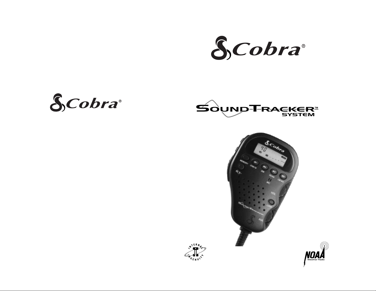
Operating instructions for your
COBRA ELECTRONICS CORPORATION
6500 W. Cortland Street
Chicago, Illinois 60707
Printed in Thailand Cobra Electronics Corp.© 1997 Part no. 480-230-P-001
COMPACT REMOTE MOUNT
CB RADIO WITH
75WXST
“Ingenious Products for
Easier Communication.”
“Cuts Noise Coming In... Strengthens Signals Going Out”
Page 2
INTRODUCTION
3
CITIZENS BAND RADIO
WITH SOUNDTRACKER
CONTENTS:
Introduction ..........................................3
Features ............................................3
Technical Support and service ..........3
Controls and Indicators ..................4/5
Included with your 75WX ....................6
Installation ............................................7
Connector Box Location....................7
Mounting Connector Box ..............8/9
Microphone Hanger ........................10
Antenna ..........................................11
Speakers..........................................12
Noise Interference ..........................12
SoundTracker System ......................13
Operation............................................13
Turning your CB On ........................14
Selecting a Channel ........................15
Activating SoundTracker ..................16
Testing SoundTracker ........................17
Setting the Squelch......................18/19
LCD Readout ..................................20
Operation (continued)
Receive / Transmit............................21
One Touch Channel 9 & 19........22/23
Key Lock ..........................................24
Frequency Display ..........................25
All Channel Scan ............................26
Weather Channel ............................27
Channel Saver..................................28
Memory Channels ......................28/29
Dual Watch ................................30/31
If you think you need service ..............32
How your CB can serve you................33
A few rules you should know ..........33
Weather Channel Messages..............34
Channel 9 Emergency Messages ......35
CB 10 Codes....................................36
Frequency Ranges................................37
Specifications ......................................38
Warranty Information ..........................39
Optional Accessories ..........................40
75 WX ST
INTRODUCTION
The Cobra 75 WX ST is the ultimate in remote mount CB transceivers and
features the SoundTracker system which dramatically eliminates annoying
static to deliver crisp, clear sound quality. The 75’s compact, state-of-theart design provides consistent, outstanding performance in almost all
conditions or situations. For ultimate satisfaction and performance from
your Cobra 75 WX ST, please review these operating instructions fully,
prior to use.
FEATURES
• SoundTracker System
• 40 CB Radio Channels
• 10 Weather Channels
• One-touch Emergency Channel 9
• One-touch Information Channel 19
• Remote Mount Installation System
• Full Featured LCD Display Panel
• Squelch Control
• Key Lock
• Channel Saver Circuitry
• Dual Watch Channel Monitor
• Full Channel Scan
• Four Memory Locations
• 10-Foot Flexible Cord
• Quick Disconnect
TECHNICAL SUPPORT
How to use your
For technical assistance, please call our Automated Help Desk
which can assist you by answering the most
frequently asked questions about Cobra products.
(773) 889-3087
24 hours a day, 7 days a week.
A Consumer Service Representative can be reached through this
same number 8:00 am - 8:00 pm, Monday through Friday, CST.
Technical assistance is also available on-line in the Frequently Asked
Question (FAQ) section at www.cobraelec.com or by e-mail
Page 3
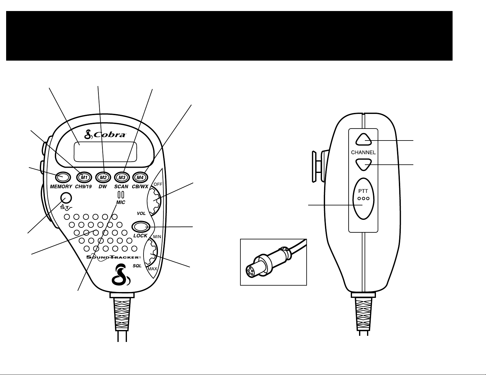
1. SoundTracker Key
2. Memory Key
3. Channel 9 / 19 / Memory Location 1 Key
4. LCD Display Panel
5. Dual Watch / Memory Location 2 Key
6. Scan / Memory Location 3 Key
7. CB / Weather Channel /
Memory Location 4 Key
8. On / Off / Volume Control
9. Lock Key
10. Squelch Control
11. Microphone
12. Speaker
13. Channel Up
14. Channel Down
15. PTT (Push-To-Talk) Key
16. Quick Disconnect Connector
INTRODUCTION
CONTROLS AND INDICATORS
5
INTRODUCTION
CONTROLS AND INDICATORS
4
1
2
3
4
5
6
7
8
9
10
13
12
14
15
11
16
Page 4
INSTALLATION
CONNECTOR BOX LOCATION
7
INTRODUCTION
COMPONENTS INCLUDED
6
LOCATION
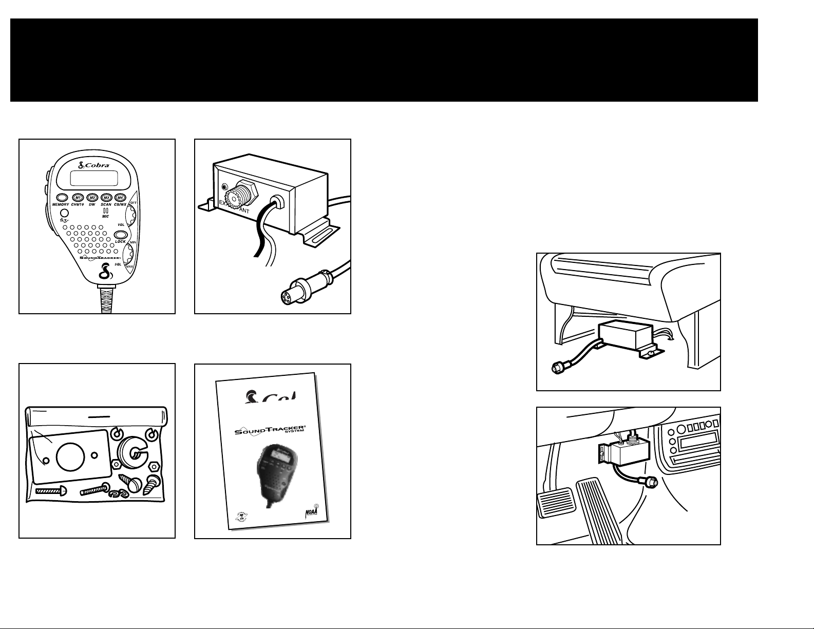
Mount your Cobra 75 WX ST Connector Box in a
convenient location, away from moisture and direct
sunlight, in a location that will not interfere with driving.
Cobra suggests mounting it either under the front seat or
on the fire wall.
UNDER THE FRONT
SEAT INSTALLATION
FIRE WALL
INSTALLATION
NOTE: Do not mount under
the hood, near heat ducts or
in direct line of the car’s
heater.
75 WX ST Transceiver
Connector Box
Installation Hardware Operating Manual
Operating instructions for your
COMPACT REMOTE MOUNT
CB RADIO WITH
75WXST
“Ingenious Products for
Easier Communication.”
“Cuts Noise Coming In... Strengthens Signals Going Out”
Page 5
INSTALLATION
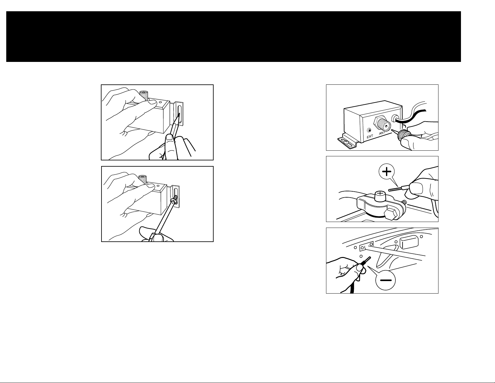
CONNECTOR BOX
9
INSTALLATION
CONNECTOR BOX
8
MOUNTING
CONNECTOR BOX
1. Hold Cobra 75 WX ST
Connector Box in exact
location desired for
mounting.
2.
Using it as a template,
mark the location
for
the mounting screws
(included).
NOTE: Make certain that
nothing will interfere with
the installation of the
mounting screws, before
drilling holes.
3. Mount Connector Box
as shown.
CONNECTING WIRES
1. Connect the antenna
cable connector.
2. Connect the red wire
marked “BATT” (+)
directly to the positive
side of the battery or to a
connection on the fuse
box that is always on.
3. Connect the black wire
marked “Ground” (-) to
the negative side of the
car, usually the chassis.
Any other location with
good electrical contact
(paint removed) will
also work.
CAUTION: Leaving the 75 WX ST on after your car is turned off can
drain your car battery when connected to a constant 12
volt source. When connected to accessory 12 volt source
unit will turn off.
Page 6
11
INSTALLING
MICROPHONE
HANGER
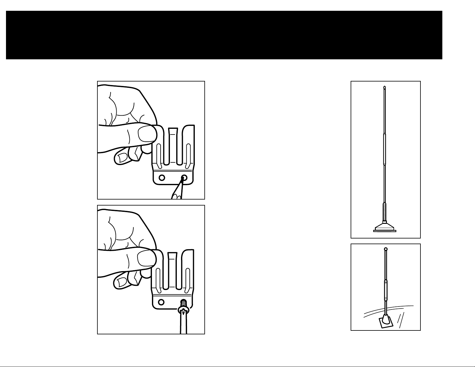
1. Hold microphone hanger
in location desired for
mounting. Make certain
that nothing will interfere
with the hanger’s
installation.
2. Mark the location for the
three mounting screws
(screws included).
3. Drill and mount
microphone hanger.
INSTALLATION
MICROPHONE HANGER
10
INSTALLATION
CB ANTENNA
CB ANTENNA INSTALLATION
For the most reliable operation and
maximum range, Cobra recommends
using a vertically polarized, quarter wave
length whip antenna (illustration A).
Shorter, loaded-type whips are adequate
when maximum range is not required
(illustration B).
NOTE: Mobile installations (cars, trucks,
boats, etc) should be made only with a
non-directional antenna system.
• A standard antenna connector
(Type SO-239) is provided on the
Connector Box for easy connection to
a standard PL-259 cable termination.
• Cobra antenna models are
recommended; see your local CB dealer
or order directly from Cobra. See order
form on page 40.
• For maximum efficiency in boat
installations, a ground plate is required,
unless the vessel has a steel hull. Consult
your CB dealer for information regarding
an adequate grounding system.
A
B
Page 7
13
12
INSTALLATION
SPEAKERS/NOISE INTERFERENCE
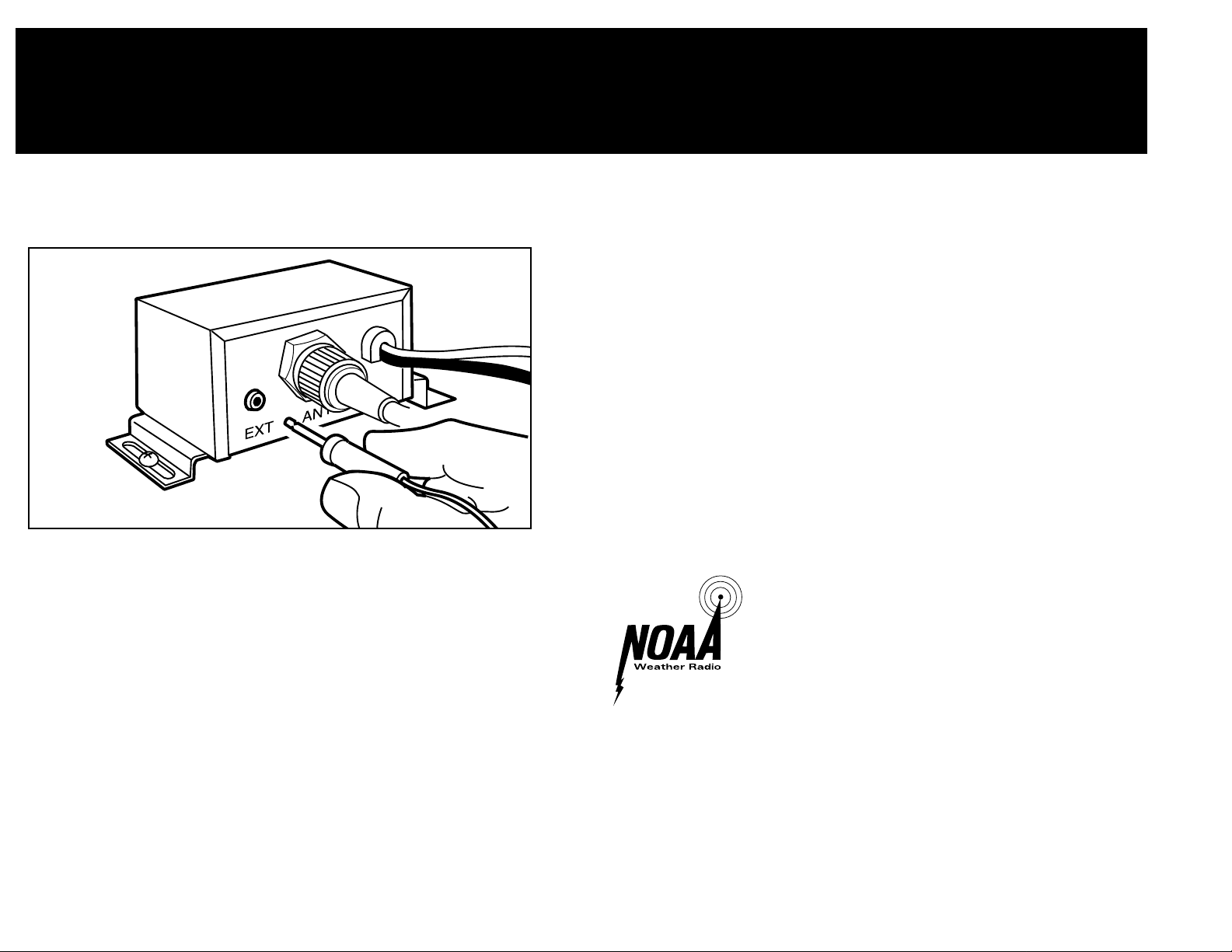
1. Mount external speaker in desired location.
2. Plug jack into the back of the Connector Box labled EXT.
*The external speaker should have 4-8 ohms impedance and be able to
handle at least 4 watts.
IGNITION NOISE INTERFERENCE
The alternator and ignition system in your vehicle may limit your ability
to receive low signal levels. Other noise interference can be the result
of several different installation variables. Consult your Cobra dealer or
a 2-way radio technician to help locate and correct the source of severe
noise interference.
EXTERNAL SPEAKER INSTALLATION
OPERATION
HOW SOUNDTRACKER WORKS
SOUNDTRACKER SYSTEM
While previous systems only “blanked out” or limited noise in higher
sound frequencies, the revolutionary new SoundTracker System actually
reduces noise while leaving the signal intact in the reception mode. In
the transmission mode, it actually strengthens the signal, providing you
with a significant reduction in noise on reception and transmission.
Sound clarity is measured by the ratio of the signal
level to the noise level. The higher the signal-to-noise
ratio, the better the sound.
HOW SOUNDTRACKER WORKS
On Reception–
“Cuts Noise Coming In”
With a normal CB, distant signals fall below the squelch level and
are unintelligible. With a SoundTracker CB, the noise level is cut
by up to 90%, which increases the signal-to-noise ratio and
dramatically improves signal clarity. This also allows you to
significantly reduce the squelch level, which greatly expands your
listening range.
On Transmission–
“Strengthens Signals Going Out”
A SoundTracker CB strengthens the transmit signal by more
effectively using the available RF power output of the CB.The
result is improved transmission signal clarity and an expanded
transmission range.
Page 8
14
OPERATION
TURNING CB ON
15
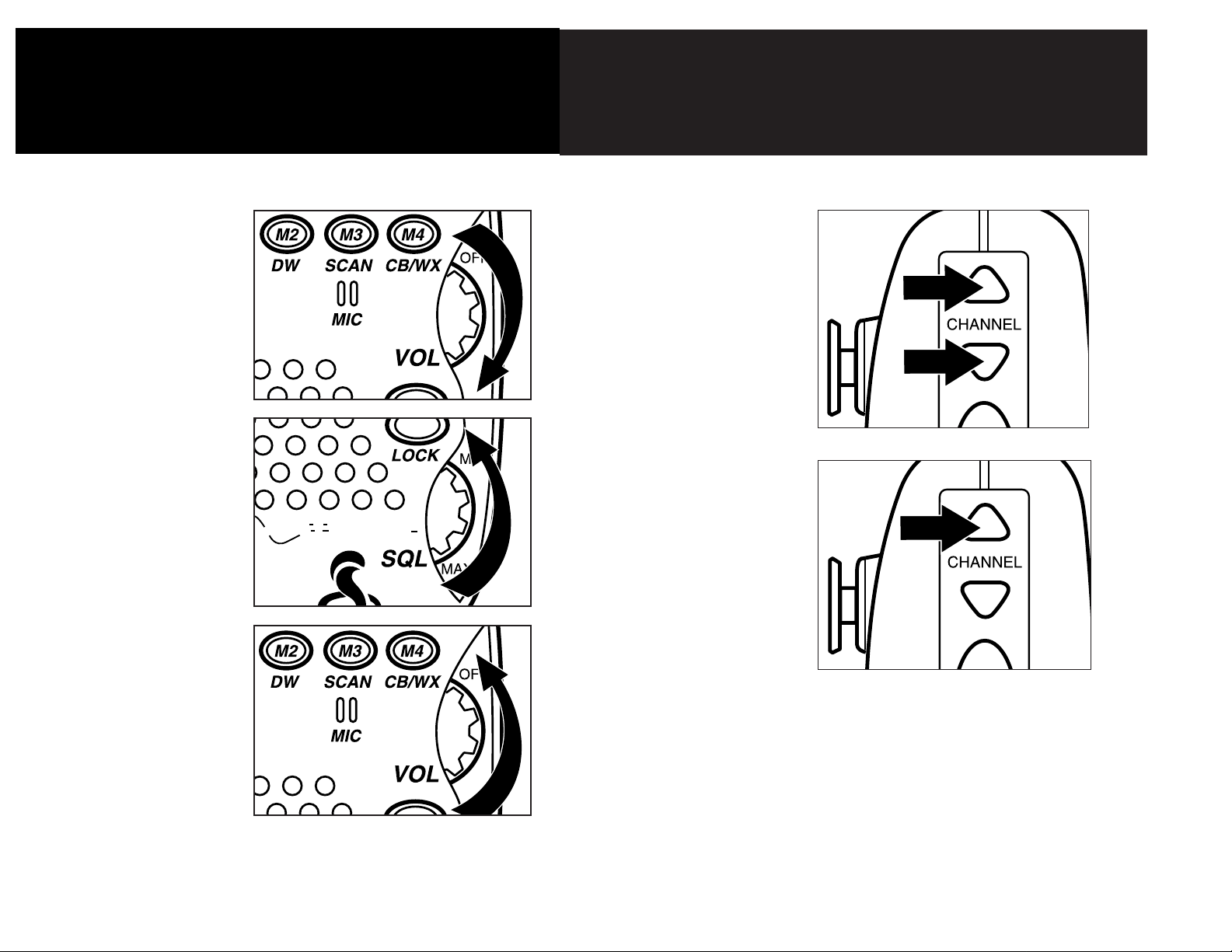
1. Rotate the power ON-
OFF Volume Control
clockwise.
2. Turn the Squelch Control
counterclockwise until
noise is heard.
3. Adjust volume to a
comfortable level.
TURNING YOUR
CB ON
OPERATION
SELECTING A CHANNEL
SELECTING A
CHANNEL
1. Change channels by
pressing either the
channel ▲ up or channel
▼ down key .
2. To quick-advance
channels, press and
hold either key.
UND
T
RACKER
TM
Page 9

40
1
3
5
9
+30 SIG
0.5 1 2 3 4 PWR
AM RX
TESTING
SOUNDTRACKER
1. Select any unused
channel on your CB.
2. Open the squelch control
fully by turning the knob
counterclock-wise until
it stops.
3. Turn the volume up
louder than your normal
listening level.
4. Depress the
SoundTracker key. Notice
the significant reduction
in noise.
S
OUND
T
RACKER
TM
17
OPERATION
TESTING SOUNDTRACKER
16
OPERATION
ACTIVATING SOUNDTRACKER
2. will be displayed on
the LCD readout.
ST
ACTIVATING
SOUNDTRACKER
1. Depress the Sound-
Tracker key.
40
1
3
5
9
+30 SIG
0.5 1 2 3 4 PWR
Page 10
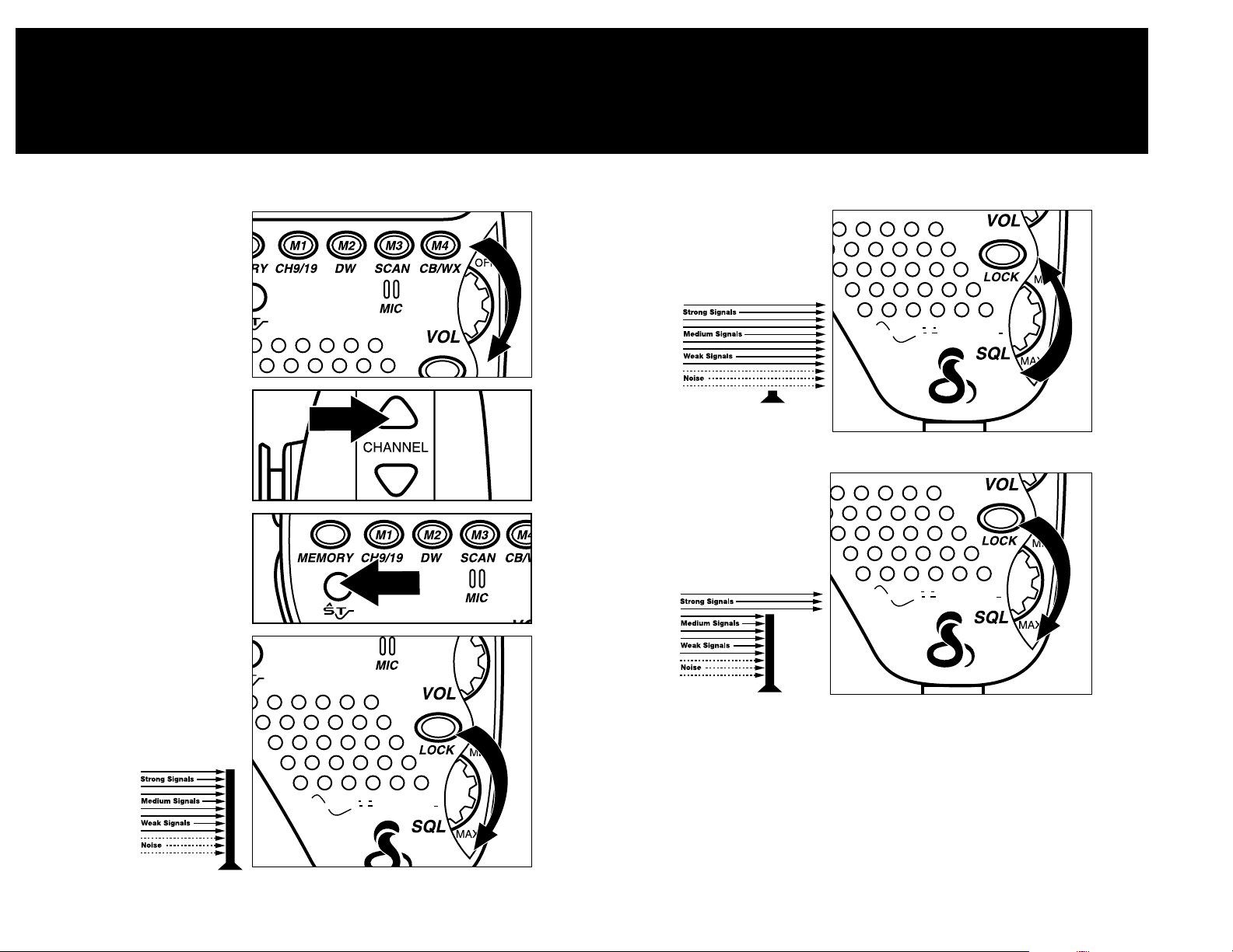
5. If you turn the squelch
control fully counterclockwise, it lowers the
“squelch gate” so low
that everything gets
through
- noise,
weak
signals
and
strong
signals.
6. To set the “squelch gate”
to the DSS-Desired
Squelch Setting, turn the
squelch control
counterclockwise until
you hear noise. Then turn
the squelch control back
clockwise
just until
the noise
stops.
Now only
strong
signals
get through.
The Desired Squelch
Setting, (DSS) only allows
actual transmissions to
come through. This
effectively blocks out
unwanted noise.
19
OPERATION
SETTING THE SQUELCH
18
OPERATION
SETTING THE SQUELCH
SETTING THE
SQUELCH
1. Turn CB on by turning
the volume control
clockwise. Adjust
the volume to a
comfortable level.
2. Before setting the squelch
control on your radio,
you must select a channel
that is not in use.
3. Turn on SoundTracker.
To achieve the Desired
Squelch Setting (DSS):
4. Think of your Squelch
Control as a gate for
incoming signals. If you
turn the Squelch Control
fully clockwise, it raises
the “squelch
gate” so
high that
no signals
get through.
S
OUND
T
RACKER
S
OUND
T
RACKER
S
OUND
T
RACKER
TM
TM
TM
Page 11
21
20
OPERATION
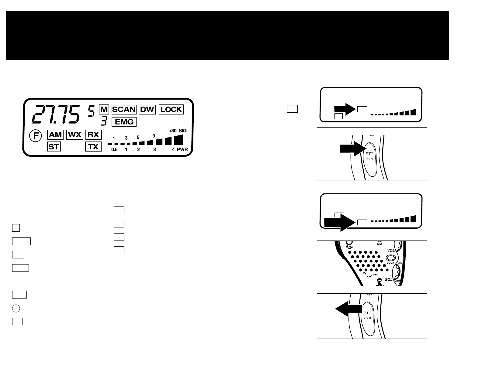
LCD READOUT
2 digit channel display / 5 digit
frequency display
= Memory Indicator
= Scan Indicator
= Dual Watch Indicator
= Lock Key Indicator
Memory Channel Number
= Emergency Channel 9
= Function key indicator
= Amplitude Modulation
= Weather Station
= Receive Indicator
= SoundTracker indicator
= Transmit Indicator
Signal Strength Meter
NOTE: To avoid damaging the LCD
display, do not subject your CB
radio to extreme temperatures
(below -5°F or above 140°F) for
extended periods of time.
TX
ST
RX
WX
AM
EMG
LOCK
DW
SCAN
M
LCD DISPLAY
Your Cobra 75 WX ST CB is designed with a liquid crystal display that
indicates channel number, frequency and the operating mode.
OPERATION
TRANSMIT/RECEIVE
TO RECEIVE
1. Your 75 WX ST is
automatically in the
receive mode and
is illuminated.
TO TRANSMIT
1. Press the Press-To-Talk
(PTT) key.
2. The TX icon will appear
3. Hold the microphone
about 2 inches from your
mouth and speak in a
normal voice.
4. Release the PTT button
and you will
automatically be in
the receive mode again.
RX
F
40
AM RX
ST
40
AM
ST TX
5
3
1
0.5 1 2 3 4 PWR
5
3
1
0.5 1 2 3 4 PWR
S
OUNDTRACKER
+30 SIG
9
+30 SIG
9
TM
Page 12
22
OPERATION
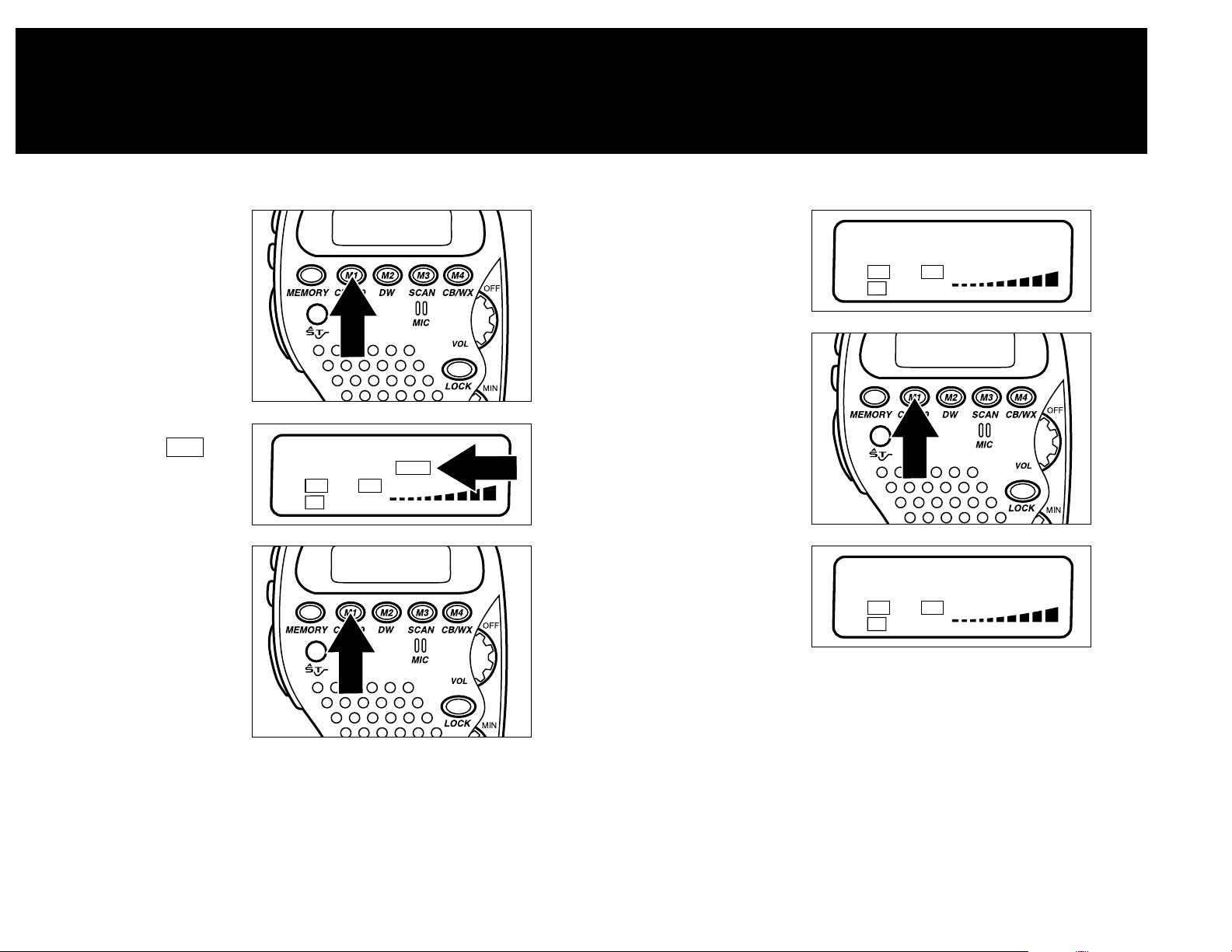
ONE TOUCH CHANNEL 9 AND 19
23
EMERGENCY
CHANNEL 9 OR
INFORMATION
CHANNEL 19
1. To access emergency
channel 9, press Channel
9/19 key once.
2.You are now on emergency
channel 9 and the
icon will appear.
3. To access information
channel 19, press Channel
9/19 key again.
EMG
4. You are now
on information
channel 19
5. Press 9/19 again
to return to the original
channel selected.
6. Original channel
OPERATION
ONE TOUCH CHANNEL 9 AND 19
9
AM RX
ST
EMG
3
1
0.5 1 2 3 4 PWR
+30 SIG
9
5
19
AM RX
ST
40
AM RX
ST
+30 SIG
9
5
3
1
0.5 1 2 3 4 PWR
+30 SIG
9
5
3
1
0.5 1 2 3 4 PWR
Page 13
25
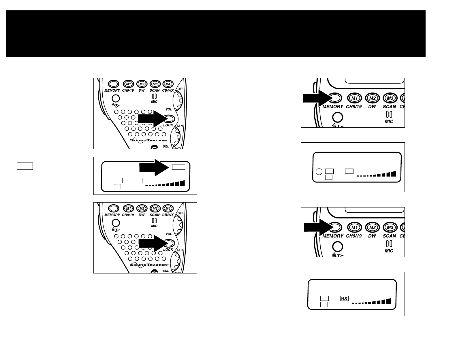
KEY LOCK
1. Press Key Lock button to
prevent unintentional
channel changing.
2.You are now locked and the
icon will appear.
3. Press Key Lock button
again to deactivate.
LOCK
OPERATION
FREQUENCY DISPLAY
24
5 DIGIT
FREQUENCY DISPLAY
1. Push and hold Memory
key for approximately
3 seconds.
2. Display will change to
the 5 digit frequency of
the channel selected.
3. Push and hold Memory
key for 3 seconds.
4. Display will change back
to channel display.
OPERATION
KEY LOCK
40
AM RX
ST
LOCK
+30 SIG
9
5
3
1
0.5 1 2 3 4 PWR
27.75
AM RX
F
ST
5
3
1
0.5 1 2 3 4 PWR
+30 SIG
9
5
AM
ST
40
+30 SIG
9
5
3
1
0.5 1 2 3 4 PWR
Page 14
27
26
OPERATION
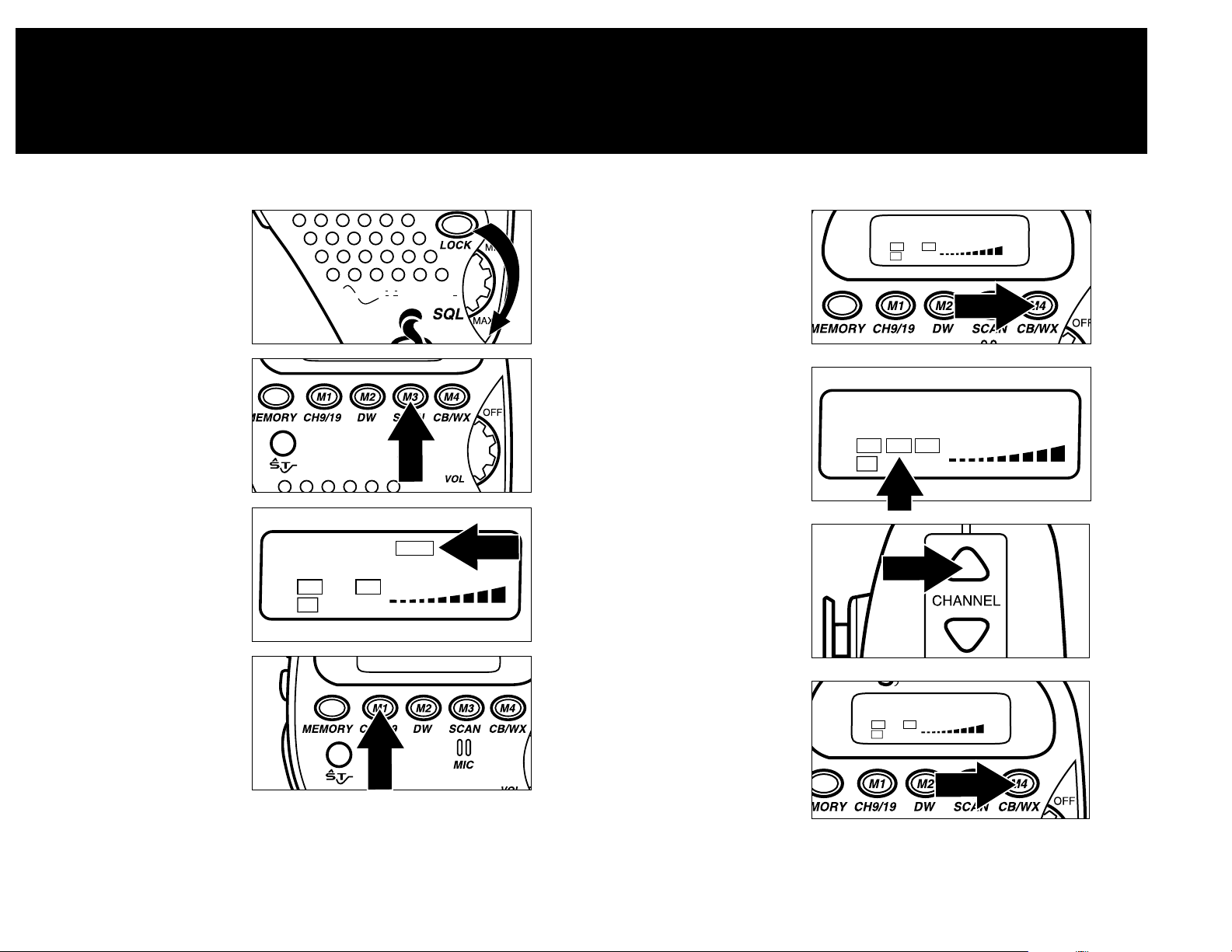
CHANNEL SCAN
ALL CHANNEL SCAN
1. Set Squelch Control (SQL)
to desired setting DSS.
*See page 18 to set DSS.
2. Press Scan key. When
activity is found on
a channel scanning
will stop.
3. Scan icon will apear.
4. Press any key to stop
scanning sequence.
NOTE.The 75 WX ST will stop scanning and monitor a channel
when it receives an incoming transmission. Five seconds
after the transmission stops, the 75 WX ST will resume the
scanning function.
OPERATION
WEATHER CHANNELS
WEATHER CHANNELS
1. Press the CB/WX key.
2. The unit will change to
the WX function and a
weather channel number
will be displayed.
2. Press Up/Down Channel
keys to locate the
weather station in
your area.
3. Press the CB/WX key to
return to a normal
CB channel.
S
OUND
40
AM RX
ST
T
RACKER
SCAN
1
0.5 1 2 3 4 PWR
TM
9
5
3
+30 SIG
40
AM
ST
1
AM WX RX
ST
RX
+30 SIG
9
5
3
1
0.5 1 2 3 4 PWR
5
3
1
0.5 1 2 3 4 PWR
+30 SIG
9
40
AM RX
ST
+30 SIG
9
5
3
1
0.5 1 2 3 4 PWR
Page 15
28
CHANNEL SAVER FEATURE*
Automatically retains the last channel used when CB is turned off and
returns you to that channel when CB is turned back on.
*To function, the “red wire” must be directly connected to either:
1. Positive (+) battery terminal.
2. Connection on the fuse box that is always on.
See installation section for details.
NOTE: Leaving the 75 WX ST on after your car is turned off can drain
your car battery when connected to a constant 12 volt source.
OPERATION
CHANNEL SAVER/MEMORY CHANNELS
29
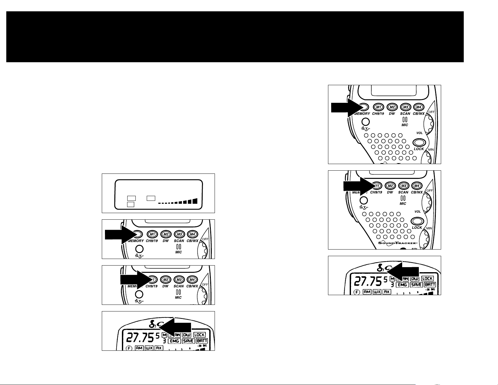
SAVING CHANNELS
IN MEMORY
1. Select desired channel to
store in memory.
2. PRESS and RELEASE the
Memory key.
3. PRESS and HOLD the
desired Memory Location
key to lock channel into
memory.
4. The Memory Location
will appear on
the display.
RETRIEVING
CHANNELS FROM
MEMORY
1. PRESS and RELEASE the
Memory key.
2. PRESS and RELEASE
the desired Memory
Location key.
3. The channel in the
memory location will
be recalled.
4. Repeat to recall other
Memory Locations.
OPERATION
MEMORY CHANNELS
40
AM RX
ST
+30 SIG
9
5
3
1
0.5 1 2 3 4 PWR
Page 16
00
30
OPERATION
DUAL WATCH
31
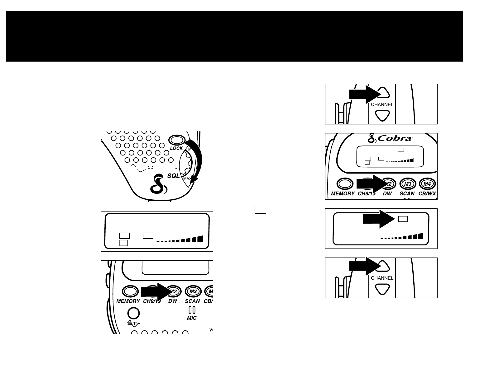
DUAL WATCH
Allows you to
simultaneously monitor any
two preselected channels at
one time.
1. Adjust squelch (SQL)
setting to the DSS level
(see page 18).
2. Set CB to one of the
stations you wish to
monitor.
3. PRESS and Hold the DW
key until a beep is heard.
S
OUND
T
RACKER
TM
NOTE:The 75 WX ST will alternate between both channels until it
receives an incoming transmission. Five seconds after the
transmission stops, it will again alternate between both channels.
OPERATION
DUAL WATCH
4. Select new channel.
5. Press and hold DW key
until a beep is heard.
6. The icon appears
and monitoring begins.
7. Press any key to stop
monitoring function.
DW
40
AM RX
ST
+30 SIG
9
5
3
1
0.5 1 2 3 4 PWR
35
AM RX
ST
1
0.5 1 2 3 4 PWR
DW
+30 SIG
9
5
3
1
0.5 1 2 3 4 PWR
DW
9
5
3
+30 SIG
Page 17
33
For technical assistance, please call our Automated Help Desk
which can assist you by answering the most
frequently asked questions about Cobra products.
(773) 889-3087
24 hours a day, 7 days a week.
A Consumer Service Representative can be reached through this same
number 8:00 am - 8:00 pm, Monday through Friday, CST.
Technical assistance is also available on-line in the
Frequently Asked Question (FAQ) section at www.cobraelec.com or by e-mail
32
HOW YOUR CB CAN SERVE YOU
• Warn of traffic tie-ups ahead.
• Provide weather and road information.
• Provide help fast in event of emergency or breakdown.
• Suggest good spots to eat and sleep.
• Make long trips more interesting, and help keep you awake.
• Provide direct contact with your office or home.
• Make friends as you travel.
• Provide “local information” to find your destination.
• Communicate with friends and family during outdoor activities.
• Help law enforcement officers by reporting drunk and reckless drivers.
A FEW RULES YOU SHOULD KNOW
1. You are not allowed to carry on a conversation with another station for
more than five minutes at a time without taking a one-minute break to
give others a chance to use the channel.
2. You are not allowed to blast others off the air by overpowering them
with illegally amplified transmitter power or illegally high antennas.
3. You can’t use the CB to promote illegal activities.
4. You are not allowed to use profanity.
5. You may not play music in your CB.
6. You may not use your CB to sell merchandise or professional service.
If You Think You Need Service, Call 773-889-3087
“If your product should require factory service please call
Cobra first before sending your unit in. This will ensure the
fastest turnaround time on your repair.”
You may be asked to send your unit to the Cobra factory. It will be necessary
to furnish the following, in order to have the product serviced and returned.
1. F or Warranty Repair proof-of-purchase, such as a mechanical
reproduction or carbon or a sales receipt will be required. If you send
the original receipt it cannot be returned.
2. The entire product, including CB unit and microphone must be sent in.
3. Enclose a description of what is happening with the unit. Include a typed
or clearly printed name and address of where the unit is to be returned.
4. Pack unit securely to prevent damage in transit. If possible, use the
original packing material.
5. Ship prepaid and insured by way of a traceable carrier (to avoid loss in
transit) such as United Parcel Service (UPS), Roadway Parcel Service
(RPS)
or First Class Insured Mail to Cobra Factory Service, Cobra
Electronics Corporation, 6500 W. Cortland St., Chicago, IL 60707.
Cobra is not responsible for units not received if package has not been
properly insured.
6.
If the unit is in warranty, upon receipt of your unit it will either be repaired
or exchanged depending on the model. Please allow approximately 3 to
4 weeks before contacting us for status. If the unit is out of warranty a
letter will automatically be sent informing you of the repair charge or
replacement charge. If you have any questions, please call 773-889-3087
for assistance.
Page 18
35
34
WEATHER CHANNEL MESSAGES
You can receive up to the minute local area weather reports provided by
NOAA (National Oceanic Atmospheric Administration) 24 hours a day,
7 days a week. An agency of the U.S. Department of Commerce, NOAA
warns of dangerous weather, charts our seas and skies, guides our use
and protection of ocean and coastal resources and conducts research to
improve our understanding and stewardship of the environment.
The National Weather Service operates about 380 stations. Approximately
90 percent of the Nation’s population is within listening range of a NOAA
Weather Radio broadcast.
A similar network of about 15 stations using the same frequencies broadcast
continuous weather information across much of southern Canada.
If you have a question concerning NOAA Weather Radio or wish to
receive a listing of NOAA Weather Radio receiver locations, please
contact your nearest National Weather Service Office, or write to
National Weather Service (Attn: W/OM11), National Oceanic and
Atmospheric Administration, Silver Spring, MD. 20910.
Note: Some areas may not have a broadcast tower within the receiving
range of your 75 WX ST.
Operating Procedure for Emergency Communications
1.
For EMERGENCY communications, set radio to Ch. 9. For
non-emergency communications, select desired Channel by pressing the
CHANNEL UP/DOWN tuning buttons until reaching the desired Channel.
Be sure the antenna is properly connected to the radio before
transmitting. Prolonged transmitting without an antenna, or use of a
poorly matched antenna, could cause damage to the transmitter.
2. When asking for aid on Channel 9 it is suggested that you request a
REACT base to respond by saying “Break Channel 9 for a REACT base”
and provide the CB DISTRESS DATA (called “CLIP”):
CALL SIGN-Identify yourself and vehicle.
LOCATION-Be exact.
INJURIES-Number. Type. Trapped?
PROBLEM- Give details and help required. Air CLIP repeatedly so any
monitor can aid you.
If you don't receive a response on Ch. 9; try Ch.14 or 19.
FCC gives the following examples of permitted and prohibited types of
communications for use on Channel 9. These are guidelines and are not
intended to be all-inclusive.
USE CHANNEL 9 FOR EMERGENCY ONLY
Permitted Example Message
Yes “A tornado sighted six miles north of town.”
No “This is observation post number 10. No tornado sighted.”
Yes “I am out of gas on Interstate 95 at mile marker 121.”
No “I am out of gas in my driveway.”
Yes “There is a four-car collision at Exit 10 on the Beltway,
send police and ambulance.”
No “Traffic is moving smoothly on the Beltway.”
Yes “Base to Unit 1, the Weather Bureau has just issued a
thunderstorm warning. Bring the sailboat into port.”
No “Attention all motorists. The Weather Bureau advises that
the snow tomorrow will accumulate 4 to 6 inches.”
Yes “There is a fire in the building on the corner of 6th and
Main Streets.”
No “This is Halloween patrol unit number 3. Everything is
quiet here.”
Page 19
37
36
CB 10-CODES
Citizens Band radio operators have largely adopted the “10-code” for
standard questions and answers. Its use permits faster communications
and better understanding in noisy areas. The following table lists some of
the more common codes and their meanings:
Code Meaning
10-1 Receiving poorly
10-2 Receiving well
10-3 Stop transmitting
10-4 OK, message received
10-5 Relay message
10-6 Busy, stand by
10-7 Out of service, leaving air
10-8 In service, subject to call
10-9 Repeat message
10-10 Transmission completed,
standing by
10-11 Talking too rapidly
10-12 Visitors present
10-13 Advise Weather/Road
conditions
10-16 Make pick up at
10-17 Urgent business
10-18 Anything for us?
10-19 Nothing for you, return to base
10-20 My location is
10-21 Call by telephone
10-22 Report in person to
10-23 Stand by
10-24 Completed last assignment
10-25 Can you contact
10-26 Disregard last information
10-27 I am moving to channel
10-28 Identify your station
10-29 Time is up for contact
10-30 Does not conform to FCC rules
10-32 I will give you a radio check
10-33 EMERGENCY TRAFFIC
10-34 Trouble at this station
10-35 Confidential information
10-36 Correct time is
Code Meaning
10-37 Wrecker needed at
10-38 Ambulance needed at
10-39 Your message delivered
10-41 Please turn to channel
10-42 Traffic accident at
10-43 Traffic Tie up at
10-44 I have a message for you
10-45 All units within range
please report
10-50 Break channel
10-60 What is next
message number?
10-62 Unable to copy,
use phone
10-63 Net directed to
10-64 Net clear
10-65 Awaiting your next
message/assignment
10-67 All units comply
10-70 Fire at
10-71
Proceed with transmission
in sequence
10-77 Negative contact
10-81 Reserve hotel room for
10-82 Reserve room for
10-84 My telephone number is
10-85 My address is
10-91 Talk closer to mike
10-93 Check my frequency on this
channel
10-94 Please give me a
long count
10-99 Mission completed, all
units secure
10-200 Police needed at
This device complies with part 15 of the FCC rules. Operation is
subject to the following conditions:
1. This device may not cause harmful interference
2. This device must accept any interference received, including
interference that may cause undesired operation.
CB Channel Freq.
Channel in MHz
1 26.965
2 26.975
3 26.985
4 27.005
5 27.015
6 27.025
7 27.035
8 27.055
9 27.065
10 27.075
11 27.085
12 27.105
13 27.115
14 27.125
15 27.135
16 27.155
17 27.165
18 27.175
19 27.185
20 27.205
CB Channel Freq.
Channel in MHz
21 27.215
22 27.225
23 27.255
24 27.235
25 27.245
26 27.265
27 27.275
28 27.285
29 27.295
30 27.305
31 27.315
32 27.325
33 27.335
34 27.345
35 27.355
36 27.365
37 27.375
38 27.385
39 27.395
40 27.405
Weather Weather Freq.
Channel in MHz
1 162.550
2 162.400
3 162.475
4 162.425
5 162.450
6 162.500
7 162.525
8 161.650
9 161.775
0 163.275
FREQUENCY RANGE
Your COBRA transceiver represents one of the most advanced AM twoway radios used as a Class D station in the Citizens Radio Service. This
unit features advanced Phase Lock Loop (PLL) circuitry providing
complete coverage of all 40 CB channels and 10 weather channels as
shown below.
Page 20

39
LIMITED TWO YEAR WARRANTY
COBRA ELECTRONICS CORPORATION warrants that its COBRA CB Radios, and
the component parts thereof, will be free of defects in workmanship and materials
for a period of two (2) years from the date of first consumer purchase. This
warranty may be enforced b y the first consumer purc haser, provided that the product
is utilized within the U.S.A.
COBRA will, without charge, repair or replace, at its option, defective CB radios,
products or component parts upon delivery to the COBRA factory Service
Department, accompanied by proof of the date of first consumer purchase, such as
a duplicated copy of a sales receipt.
You must pay any initial shipping charges required to ship the product for warranty
service, but the return charges will be at Cobra's expense, if the product is repaired
or replaced under warranty. For further details concerning procedures for obtaining
service, see the “If You Think You Need Service” section of the Owner’s Manual.
Exclusions: This limited warranty does not apply; 1) to any product damaged by
accident; 2) in the event of misuse or abuse of the product or as a result of
unauthorized alterations or repairs; 3) if the serial number has been altered, defaced
or removed; 4) if the owner of the product resides outside the U.S.A.
All implied warranties, including warranties of merchantability and fitness for a
particular purpose are limited in duration to the length of this warranty.
COBRA shall not be liable for any incidental, consequential or other
damages; including, without limitation, damages resulting from loss of use or
cost of installation.
Some states do not allow limitations on how long an implied warranty lasts and/or
do not allow the exclusion or limitation of incidental or consequential damages, so
the above limitations may not apply to you.
COBRA ELECTRONICS CORPORATION
6500 W. Cortland Street
Chicago, Illinois 60707
38
75WXST SPECIFICATIONS
GENERAL
CHANNELS CB - 40 CH
WEATHER - 10 CH
FREQUENCY RANGE CB - 26.965 TO 27.405 MHZ
WEATHER - 161.650 TO 163.275 MHZ
FREQUENCY TOLERANCE 0.005 %
FREQUENCY CONTROL PLL (PHASE LOCK LOOP) SYNTHESIZER
OPERATING TEMPERATURE RANGE -30° C TO + 65° C
MICROPHONE ELECTRET, PUSH-TO-TALK
INPUT VOLTAGE 13.8 VDC, EXTERNAL
ANTENNA CONNECTOR SO 239
METER LCD DISPLAY, ICONS
SIZE L 2 3/4" x W 1 7/8" x H 4 1/4"
WEIGHT 1 LB.
TRANSMITTER
POWER OUTPUT 4.0 W AT 13.8 VDC
MODULATION AM
FREQUENCY RESPONSE 300 - 3000 HZ AT -6 DB
OUTPUT IMPEDANCE 50 OHMS, UNBALANCED
RECEIVER
CB
SENSITIVITY LESS THAN 1 uV FOR 10 DB S/N
IF FREQUENCY DUAL CONVERSION
1 ST - 10.690 MHZ, 2ND - 455 KHZ
AUDIO OUTPUT 500 mW MAXIMUM AT 10 % THD
FREQUENCY RESPONSE 300 - 3000 HZ AT -6 DB
2ND IF IMAGE REJECTION GREATER THAN 60 DB
ADJACENT CH. REJECTION 50 DB MIN.
AUTOMATIC NOISE LIMITER BUILT- IN.
FREQUENCY CONTROL PLL (PHASE LOCK LOOP)
WEATHER
SENSITIVITY LESS THAN 1 uV FOR 12 DB SINAD
IF FREQUENCY DUAL CONVERSION
1st: -10.690 MHz
2nd: -455 KHz
AUDIO OUTPUT MAXIMUM 500 mW AT 10 % THD
FREQUENCY RESPONSE 300 - 3000 HZ AT -6 DB
Page 21
40
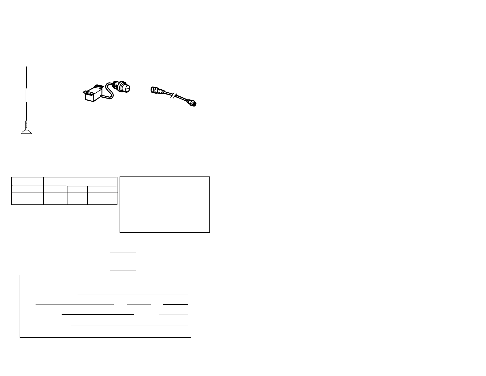
High Performance
Magnetic Mount
Weather/CB Antenna.
ATW-400 $39.95
Remote connector box.
AC-701 $29.95
4 foot extension cord.
AC-702 $19.95
OPTIONAL ACCESSORIES
You can find these fine accessories at your local Cobra CB dealer.
If you wish, you can order directly from Cobra
Order by phone:
Call 1-773-889-3087 (Press 1 from the main menu) 8a.m.-8p.m. M-F CST.
Order by mail or fax: Please fill out order form below, and mail/fax directly to Cobra.
Fax to:
1-773-622-2269
Please print clearly:
Name
Address (Not P.O. Box)
City State Zip
Credit Card No. Exp. Date
Customer Signature
Circle One: Visa MasterCard Discover
Allow 4 to 6 weeks for delivery. Offer valid in Continental U.S. only.
★★
Illinois residents add 7%
★★
Cook Co. residents add .75% (7.75% total)
★★
Chicago residents add 1% (8.75% total)
★★
Indiana residents add 5%
★★
Michigan residents add 4 %
★★
Minnesota residents add 6%
★★
Ohio residents add 6%
★★
Wisconsin residents add 5%
Part No. Cost Ea. X Qty. = Amount
AC-701 $29.95
AC-702 $19.95
ATW-400 $39.95
Amount
(Tax if applicable)
Shipping//handling $3.75
Total
Mail to:
Cobra Accessories Dept.
6500 W. Cortland St.,
Chicago, IL 60707
(Prices subject to change without notice)
 Loading...