

Page 1
UK75ST-English-UK.qx 6/15/99 3:56 PM Page 2
COBRA ELECTRONICS CORPORATION
6500 W. Cortland Street
Chicago, Illinois 60707 U.S.A.
www.cobraelec.com
UK75ST
C O M PACT REMOTE-MOUNT CB RADIO W I T H
KO M PAKTES, FERNMONTIERBARES CB-FUNKGERÄT MIT
RADIO COMPAC TA DE BA N DA CIUDA DA NA (CB) DE MONTAJE REMOTO, CON
RADIO CB DE FAIBLES DIMENSIONS A INSTA L L ATION A DISTANCE AV E C
R I C E T R A S M E T T I TORE CB COMPAT TO MONTABILE A DISTANZA CON
Cobra Electronics Corp.© 1998
“Ingenious Products for
Easier Communication.”
Page 2

UK75ST-English-UK.qx 6/15/99 3:56 PM Page 4
Operating instructions for your
UK75ST
C O M PACT REMOT E - M O U N T
C B RADIO W I T H
“Cuts Noise Coming In... Strengthens Signals Going Out”
“Ingenious Products for
Easier Communication.”
Downloaded from www.cbradio.nl
Page 3
UK75ST-English-UK.qx 6/15/99 3:56 PM Page 6
How to use your
CITIZENS BAND RADIO
WITH SOUNDTRACKER
CONTENTS (SECTION A - ENGLISH):
Introduction ..........................................2
Features ............................................2
Notice................................................2
Controls and Indicators ..................3/4
Included with your UK75ST ..................5
Installation ............................................6
Connector Box Location....................6
Mounting Connector Box..................7
Connecting Wires..............................8
Installing CB Hanger..........................9
Antenna ..........................................10
Speakers..........................................11
Noise Interference ..........................11
SoundTracker System ......................12
Operation ............................................13
Turning your CB On ........................13
Selecting Mode (EU - UK)................14
Selecting a Channel ........................14
Activating SoundTracker ..................15
Setting the Squelch ......................16/17
LCD Readout ..................................18
Operation (continued)
Receive / Transmit............................19
One-Touch Channel 19....................20
Key Lock..........................................21
Frequency Display ..........................22
All-Channel Scan ............................23
Channel Saver..................................24
Memory Channels ......................24/25
Dual Watch ................................26/27
How your CB can serve you................28
A few rules you should know ..........28
CB 10-Codes....................................29
Frequency Ranges ..........................30/31
Specifications ......................................32
Optional Accessories ..........................33
Deutsch ................................Abschnitt B
Español ....................................Sección C
Français....................................Section D
Italiano ....................................Sezione E
UK75ST
INTRODUCTION
INTRODUCTION
The Cobra UK75ST is the ultimate in remote-mount CB transceivers and
features the SoundTracker system which dramatically eliminates annoying
static to deliver crisp, clear sound quality.The 75’s compact, state-of-theart design provides consistent, outstanding performance in almost all
conditions or situations. To get the best performance from your Cobra
UK75ST, please read these operating instructions fully,before using the
unit.
FEATURES
• Complies with UK MPT 1382
• SoundTracker System
• 40 European (CEPT) and
40 UK FM CB Radio Channels
• One-touch Channel 19
• Remote-Mount Installation System
• Full-Featured LCD Display Panel
• Squelch Control
• Key Lock
• Channel Saver Circuitry
• Dual Watch Channel Monitor
• Full Channel Scan
• Five Memory Locations
• 3 metre (10-Foot) Flexible Cord
• Quick-Disconnect
NOTICE
A licence is required for use in the UK. Please contact your local CB
dealer for additional information.
2
Page 4

UK75ST-English-UK.qx 6/15/99 3:56 PM Page 8
INTRODUCTION
CONTROLS AND INDICATORS
3
4
3
2
1
5
6
7
8
9
INTRODUCTION
CONTROLS AND INDICATORS
1. SoundTracker Key
2. Memory Key
3. Channel 19 / Memory Location 1 Key
4. LCD Display Panel
5. Dual Watch / Memory Location 2 Key
6. Scan / Memory Location 3 Key
7. Display / Memory Location 4 Key
8. On / Off / Volume Control
9. Lock Key / Memory
Location 5 Key
10. Squelch Control
11. Microphone
12. Speaker
13. Channel Up Key
14. Channel Down Key
15. PTT (Push-To-Talk) Key
16. Quick-Disconnect Connector
15
16
4
13
14
12
10
11
Page 5
UK75ST-English-UK.qx 6/15/99 3:56 PM Page 10
INTRODUCTION
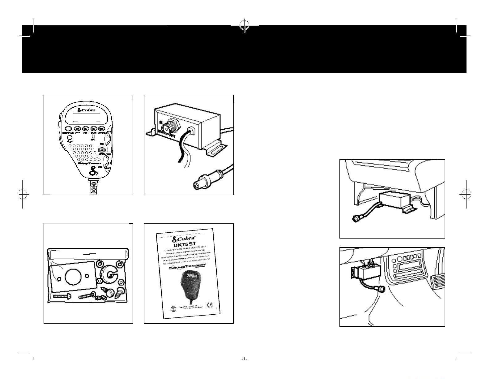
COMPONENTS INCLUDED
5
UK75ST Transceiver
INSTALLATION
CONNECTOR BOX LOCATION
6
LOCATION
Mount your Cobra UK75ST Connector Box in a
convenient location, away from moisture and direct
sunlight, in a location that will not interfere with driving.
Cobra suggests mounting it either under the front seat or
on the front bulkhead.
UNDER THE FRONT
SEAT INSTALLATION
Connector Box
Installation Hardwar e Operating Manual
FRONT BULKHEAD
INSTALLATION
NOTE: Do not mount under
the bonnet, near heat ducts or
directly in line with heater
ducts.
Page 6
UK75ST-English-UK.qx 6/15/99 3:56 PM Page 12
INSTALLATION
CONNECTOR BOX LOCATION
7
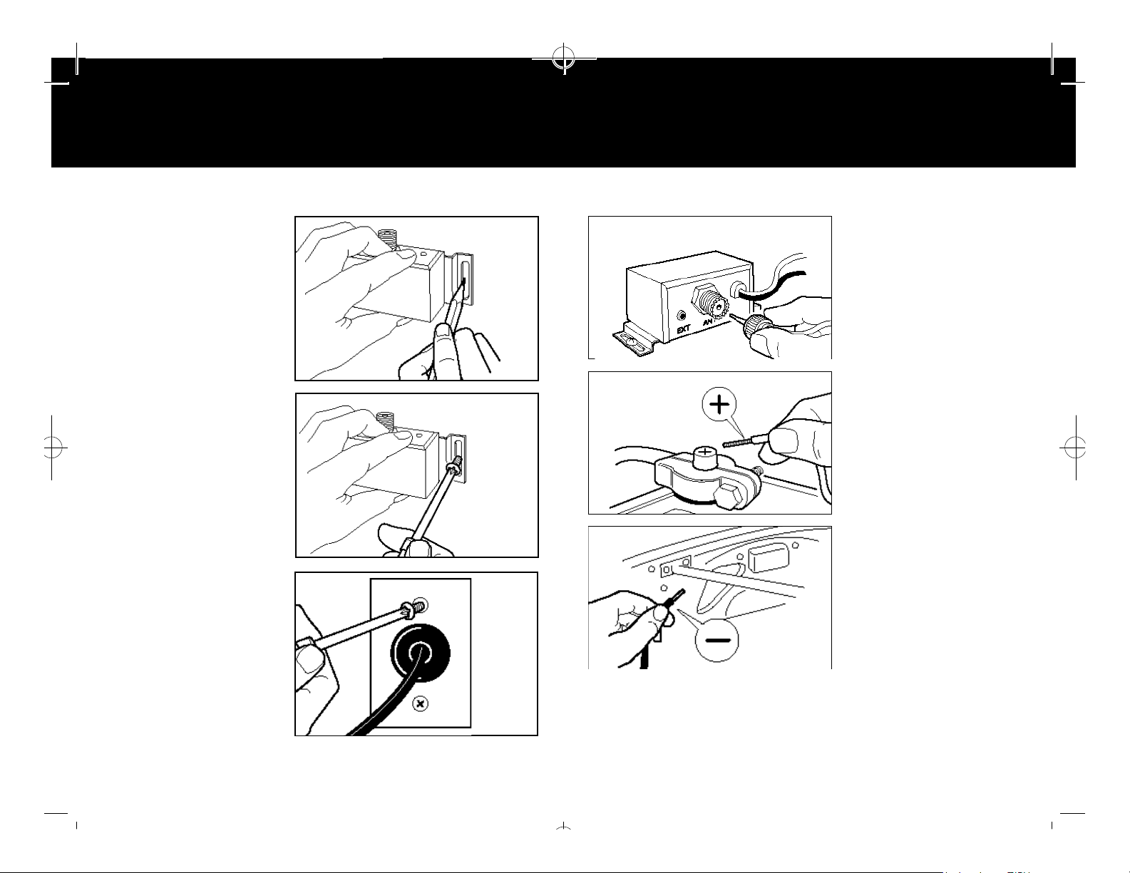
MOUNTING
CONNECTOR BOX
1. Hold Cobra UK75ST
Connector Box in exact
location desired for
mounting.
2.
Using it as a template,
mark the location
the mounting screws
(included).
NOTE: Make certain that
nothing will interfere with
the installation of the
mounting screws, before
drilling holes.
3. Mount Connector Box
as shown.
MOUNTING
THROUGH FRONT
BULKHEAD
1. Drill hole through
bulkhead.
for
INSTALLATION
CONNECTOR BOX
8
CONNECTING WIRES
1. Connect the antenna
cable connector.
2. Connect the red wire
marked “BATT” (+)
directly to the positive
side of the battery or to a
connection on the fusebox that is always live.
3. Connect the black wire
marked (-) “Earth” to the
negative side of the car,
usually the chassis. Any
other location with good
electrical contact (paint
removed) will
also work.
2.
Bolt plate and grommet to
bulkhead.
3. Push cable through
grommet.
The UK75ST is designed for 12 VDC, negative ground vehicles only.
CAUTION: If the UK75ST is connected to a constant 12-volt source,
leaving it switched on after the engine is turned off may drain
the car battery. If the UK75ST is connected to an accessory
12-volt source, it will switch off when the engine is turned off,
and reset to Channel 1.
Page 7
UK75ST-English-UK.qx 6/15/99 3:56 PM Page 14
INSTALLATION
CB HANGER
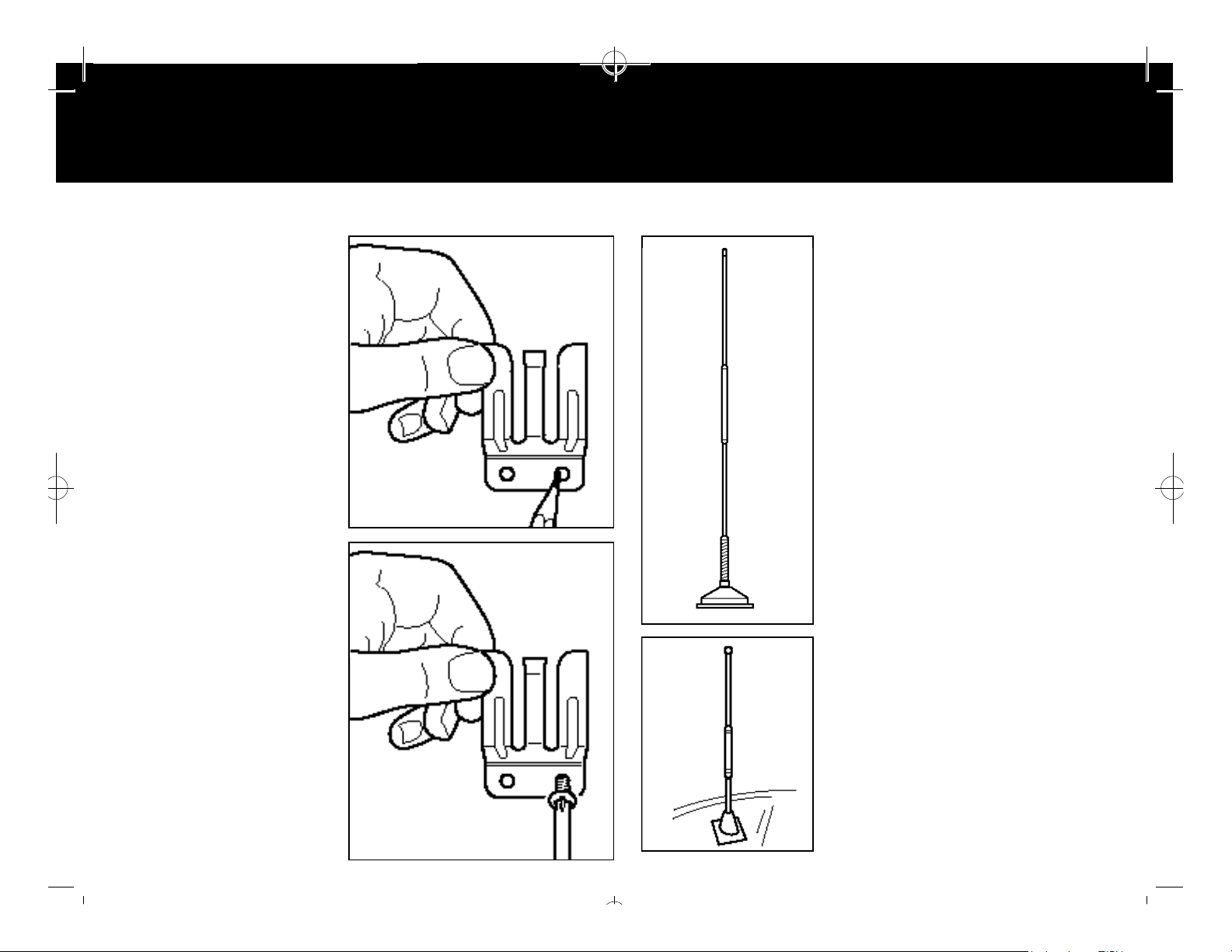
INSTALLING
CB HANGER
1. Hold CB hanger in
location desired for
mounting. Make certain
that nothing will interfere
with the hanger’s
installation.
2. Mark the location for the
two mounting screws
(screws included).
3. Drill holes and mount CB
hanger.
INSTALLATION
CB ANTENNA
109
A
CB ANTENNA INSTALLATION
For the most reliable operation and
maximum range, Cobra recommends
using a vertically polarized, quarter
wavelength whip antenna (illustration A).
Shorter, loaded-type whips are adequate
when maximum range is not required
(illustration B).
NOTE: Mobile installations (cars, vans,
lorries, boats, etc) should be made only
with a non-directional antenna system.
• A standard antenna connector
(Type SO-239) is provided on the
Connector Box for easy connection to
a standard PL-259 cable termination.
• Cobra antenna models are
recommended; see your local CB dealer
or order directly from Cobra.
• For maximum efficiency in boat
installations, an earthing plate is required,
B
unless the vessel has a steel hull. Consult
your CB dealer for information regarding
an adequate earthing system.
• Be sure that the antenna is properly
connected and tuned (SWR) to the radio
before transmitting. Prolonged transmitting
without an antenna, or use of a poorly
matched antenna, could cause damage to
the transmitter.
Page 8
UK75ST-English-UK.qx 6/15/99 3:56 PM Page 16
INSTALLATION
SPEAKERS/NOISE INTERFERENCE
11
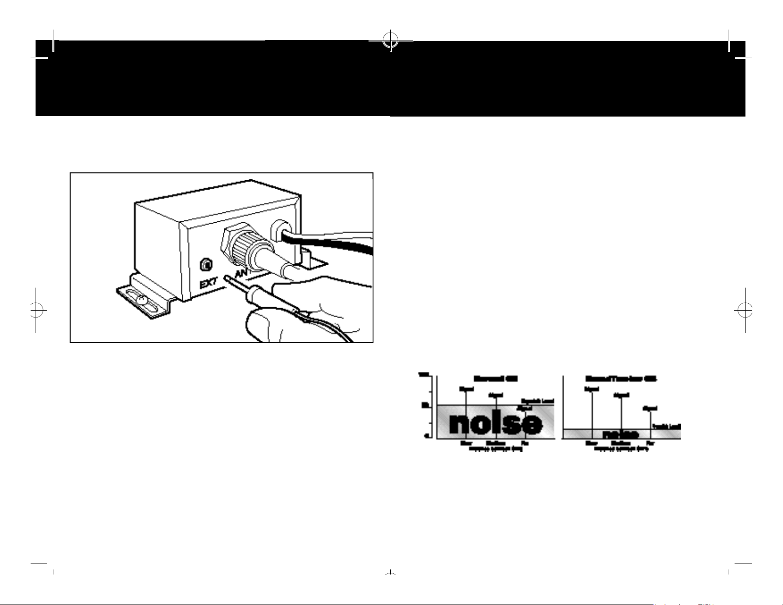
EXTERNAL SPEAKER INSTALLATION
1. Mount external speaker in desired location.*
OPERATION
HOW SOUNDTRACKER WORKS
SOUNDTRACKER SYSTEM
While previous systems only “blanked out” or limited noise in higher
sound frequencies, the revolutionary new SoundTracker System actually
reduces noise while leaving the signal intact in the reception mode. In
the transmission mode, it actually strengthens the signal, providing you
with a significant reduction in noise on reception and transmission.
Sound clarity is measured by the ratio of the signal
level to the noise level. The higher the signal-to-noise
ratio, the better the sound.
HOW SOUNDTRACKER WORKS
On Reception
With a normal CB, distant signals fall below the squelch level and
are unintelligible. With a SoundTracker CB, the noise level is cut
by up to 90%, which increases the signal-to-noise ratio and
dramatically improves signal clarity. This also allows you to
significantly reduce the squelch level, which greatly expands your
listening range.
–
“Cuts Noise Coming In”
12
2. Plug jack into the socket marked EXT on the back of the Connector
Box.
*The external speaker should have 4-8 ohms impedance and be able to
handle at least 4 watts.
IGNITION NOISE INTERFERENCE
The alternator and ignition system in your vehicle may limit your ability
to receive low signal levels. Other noise interference can be the result
of several different installation variables. Consult your Cobra dealer or
a 2-way radio technician to help locate and correct the source of severe
noise interference.
On Tra n s m i s s i on
A SoundTracker CB strengthens the transmit signal by more
effectively using the available RF power output of the CB.The
result is improved transmission signal clarity and an expanded
transmission range.
–
“ S t rengthens Signals Going Out”
Page 9

UK75ST-English-UK.qx 6/15/99 3:56 PM Page 18
OPERATION
TURNING CB ON
13
TURNING YOUR
CB ON
1. Rotate the power ON-
OFF Volume Control
clockwise.
2. Turn the Squelch Control
anticlockwise until noise
is heard.
3. Adjust volume to a
comfortable level.
OPERATION
SELECTING A CHANNEL
14
SELECTING MODE
(UK - EU)
1. Press and hold
MEM/MODE key to
select proper mode
2. Selected mode icon UK
or EU will display.
SELECTING A
CHANNEL
1. Change channels by
pressing either the
channel ▲ up or channel
▼ down key .
2. To quick-advance
channels, press and
hold either key.
Page 10

UK75ST-English-UK.qx 6/15/99 3:56 PM Page 20
OPERATION
ACTIVATING SOUNDTRACKER
15
ACTIVATING
SOUNDTRACKER
1. Depress the Sound-
Tracker key.
ST
2. will be displayed on
the LCD readout.
OPERATION
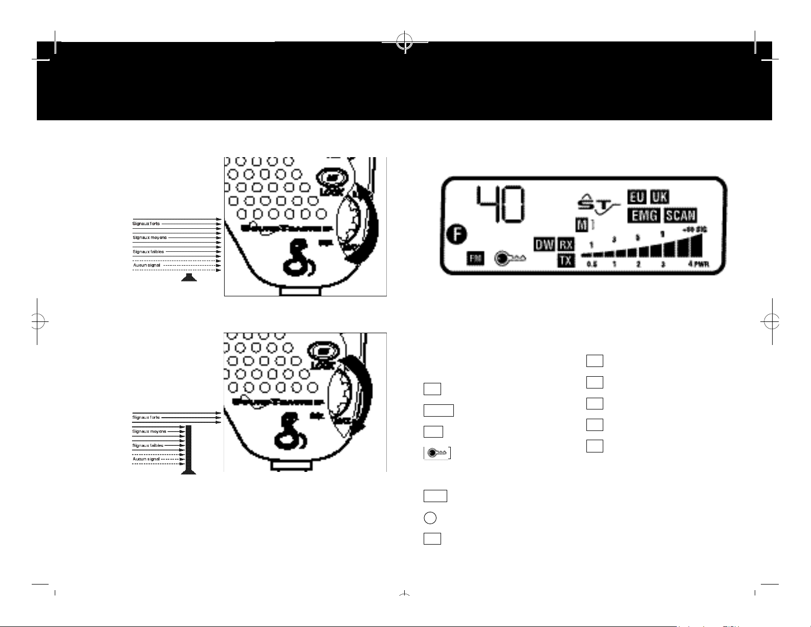
SETTING THE SQUELCH
16
SETTING THE
SQUELCH
1. Turn CB on by turning
the volume control
clockwise. Adjust
the volume to a
comfortable level.
2. Before setting the squelch
control on your radio,
you must select a channel
that is not in use.
3. Turn on SoundTracker.
To achieve the Desired
Squelch Setting (DSS):
4. Think of your Squelch
Control as a gate for
incoming signals. If you
turn the Squelch Control
fully clockwise,
it raises the
“squelch gate”
so high that no
signals get
through.
Page 11
UK75ST-English-UK.qx 6/15/99 3:57 PM Page 22
OPERATION
SETTING THE SQUELCH
5. If you turn the squelch
control fully
anticlockwise, it lowers
the “squelch gate” so low
that everything gets
through
- noise,
weak
signals
and
strong
signals.
6. To set the “squelch gate”
to the DSS (Desired
Squelch Setting), turn the
squelch control
anticlockwise until you
hear noise. Then turn the
squelch control back
clockwise until the noise
just stops. N ow only
signals as
strong as
or stronger
than the
g a t e
setting can
p a s s
through the gate and be
h e a r d .
The Desired Squelch Setting, (DSS) only allows actual transmissions to
come through. This effectively blocks out unwanted noise.
OPERATION
LCD READOUT
LCD DISPLAY
Your Cobra UK75ST CB is designed with a liquid crystal display that
indicates channel number, frequency and the operating mode.
2-digit channel display / 5-digit
frequency display
M
= Memory Indicator
SCAN
= Scan Indicator
D W
= Dual Watch Indicator
= Lock Key Indicator
Memory Channel Number
E M G
= Instant Channel 19
= Function key indicator
F
E U
= European (CEPT) Band
U K
= UK Band
F M
= Frequency Modulation
RX
= Receive Indicator
ST
= SoundTracker indicator
TX
= Transmit Indicator
Signal Strength Meter
NOTE: To avoid damaging the LCD
display, do not subject your CB
radio to extreme temperatures
(below -20°C or above 60°C) for
extended periods of time.
1817
Page 12

UK75ST-English-UK.qx 6/15/99 3:57 PM Page 24
OPERATION
TRANSMIT/RECEIVE
TO RECEIVE
1. Your UK75ST is
automatically in the
receive mode and
is illuminated.
TOTRANSMIT
1. Press the Press-To-Talk
(PTT) key.
2. The TX icon will appear
3. Hold the microphone
about 2 inches from your
mouth and speak in a
normal voice.
RX
OPERATION
ONE-TOUCH CHANNEL 19
2019
INSTANT CHANNEL 19
1. To access instant channel
19, press Channel 19 key
once.
2 .You are now on instant
channel 19 and the
icon will appear.
3. Press CH 19 again
to return to the original
channel selected.
E M G
4. Release the PTT button
and you will
automatically be in
the receive mode again.
4. Original channel
Page 13

UK75ST-English-UK.qx 6/15/99 3:57 PM Page 26
OPERATION
KEY LOCK
KEY LOCK
1. Press Key Lock button to
prevent unintentional
channel changing.
2 .You are now locked and the
icon will appear.
3. Press Key Lock button
again to deactivate.
OPERATION
CHANNEL SCAN
2221
5-DIGIT
FREQUENCY DISPLAY
1. Press and release Display
key.
2. Display will change to
the 5-digit frequency of
the channel selected.
3. Press and release Display
key.
4. Display will change back
to channel display.
Page 14

UK75ST-English-UK.qx 6/15/99 3:57 PM Page 28
OPERATION
CHANNEL SCAN
23
ALL-CHANNEL SCAN
1. Set Squelch Control (SQL)
to the DSS (Desired
Squelch Setting).
*See page 16 to set DSS.
2. Press and release Scan
key*. When activity is
found on a channel,
scanning will stop.
* Unit will begin to scan all 40
channels within selected band
(EU or UK). Press and hold
SCAN key for 2 seconds.
3. Scan icon will apear.
OPERATION
CHANNEL SAVER/MEMORY CHANNELS
24
CHANNEL SAVER FEATURE*
Automatically retains the last channel used when CB is turned off and
returns you to that channel when CB is turned back on.
*For this feature to function, the red wire must be directly connected to
either:
1. Positive (+) battery terminal.
2. Connection on the fuse-box that is always live.
See installation section for details.
NOTE: If the UK75ST is connected to a constant 12-volt source, leaving it
switched on after the engine is turned off may drain the car battery.
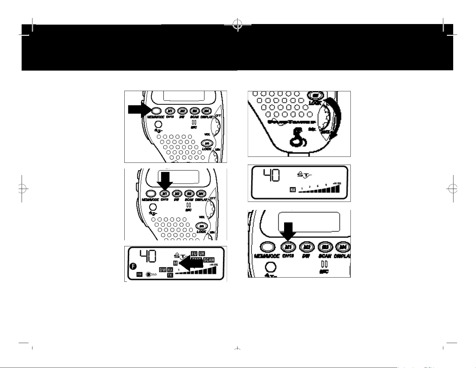
SAVING CHANNELS
IN MEMORY
1. Select desired channel to
store in memory.
2. Press and release the
Memory key.
4. Press any key to stop
scanning sequence.
N OT E . The UK75ST will stop scanning and monitor a channel when it
r e c e ives an incoming transmission. Five seconds after the
t ransmission stops, the UK75ST will resume the scanning function.
To resume scan during REC mode, press Scan key again twice.
3. Press and hold the
desired Memory Location
key to lock channel into
memory.
4. The Memory Location
will appear on
the display.
Page 15
UK75ST-English-UK.qx 6/15/99 3:57 PM Page 30
OPERATION
MEMORY CHANNELS
25
RETRIEVING
CHANNELS FROM
MEMORY
1. Press and release the
Memory key.
2. Press and release
the desired Memory
Location key.
OPERATION
31
DUAL WATCH
26
DUAL WATCH
Allows you to monitor any
two preselected channels at
the same time.
1. Adjust squelch (SQL)
setting to the DSS level
(see page 16).
2. Set CB to one of the
channels you wish to
monitor.
3. The channel in the
memory location will
be recalled.
4. Repeat to recall other
Memory Locations.
3. Press and hold the DW
key until a beep is heard.
Page 16

UK75ST-English-UK.qx 6/15/99 3:57 PM Page 32
OPERATION
DUAL WATCH
27
4. Select second channel.
5. Press and hold DW key
until a beep is heard.
6. The DW icon appears
and monitoring begins.
28
HOW YOUR CB CAN SERVE YOU
• Warn of traffic delays ahead.
• Provide weather and road information.
• Provide help fast in event of emergency or breakdown.
• Suggest good spots to eat and sleep.
• Make long trips more interesting, and help keep you awake.
• Provide direct contact (subject to conditions) with your office or home.
• Let you make friends as you travel.
• Provide local information to find your destination.
• Let you communicate with friends and family during outdoor activities.
A FEW RULES YOU SHOULD KNOW
1. You should not carry on a conversation with another station for more
than five minutes at a time without taking a one-minute break to give
others a chance to use the channel.
2. You should not blast others off the air by overpowering them with
illegally amplified transmitter power or illegally high antennas.
3. You should not use the CB to promote illegal activities.
4. You should not use bad language.
5. You should not play music over your CB.
6. You should not use your CB to sell merchandise or professional
services.
7. Press any key to stop
monitoring function.
NOTE:The UK75ST will alternate between both channels until it receives
an incoming transmission. Five seconds after the transmission
stops, it will again alternate between both channels.
THE USE OF THIS CB PRODUCT INVOLVES THE
PUBLIC AIRWAYS AND ITS USE MAY BE SUBJECT TO
LOCAL LAWS, REGULATIONS, AND ORDINANCES.
BEFORE USING THE PRODUCT YOU SHOULD
CHECK TO SEE THAT THE CONTEMPLATED USE
DOES NOT VIOLATE ANY LOCAL LAW,
REGULATION OR ORDINANCE THAT MAY BE
APPLICABLE.
Page 17

UK75ST-English-UK.qx 6/15/99 3:57 PM Page 34
29
CB 10-CODES
Citizens Band radio operators have largely adopted the “10-code” for
standard questions and answers. Its use permits faster communications
and better understanding in noisy areas. The following table lists some of
the more common codes and their meanings:
Code Meaning
10-1 Receiving poorly
10-2 Receiving well
10-3 Stop transmitting
10-4 OK, message received
10-5 Relay message
10-6 Busy, stand by
10-7 Out of service, leaving air
10-8 In service, subject to call
10-9 Repeat message
10-10 Transmission completed,
standing by
10-11 Talking too rapidly
10-12 Visitors present
10-13 Advise Weather/Road
conditions
10-16 Make pick up at
10-17 Urgent business
10-18 Anything for us?
10-19 Nothing for you, return to base
10-20 My location is
10-21 Call by telephone
10-22 Report in person to
10-23 Stand by
10-24 Completed last assignment
10-25 Can you contact
10-26 Disregard last information
10-27 I am moving to channel
10-28 Identify your station
10-29 Time is up for contact
10-30 Does not conform
10-32 I will give you a radio check
10-33 EMERGENCY TRAFFIC
10-34 Trouble at this station
10-35 Confidential information
10-36 Correct time is
Code Meaning
10-37 Breakdown truck needed at
10-38 Ambulance needed at
10-39 Your message delivered
10-41 Please turn to channel
10-42 Traffic accident at
10-43 Traffic delay at
10-44 I have a message for you
10-45 All units within range
10-50 Break channel
10-60 What is next
10-62 Unable to copy,
10-63 Net directed to
10-64 Net clear
10-65 Awaiting your next
10-67 All units comply
10-70 Fire at
10-71
10-77 Negative contact
10-81 Reserve hotel room for
10-82 Reserve room for
10-84 My telephone number is
10-85 My address is
10-91 Talk closer to mike
10-93 Check my frequency on this
10-94 Please give me a
10-99 Mission completed, all
10-200 Police needed at
please report
message number?
use phone
message/assignment
Proceed with transmission
in sequence
channel
long count
units secure
FREQUENCY RANGE
Your COBRA transceiver represents one of the most advanced FM twoway radios used. This unit features advanced Phase Lock Loop (PLL)
circuitry providing complete coverage of 40 European (CEPT) and
40 UK FM CB channels as shown below.
UK CB Channel Freq.
Channel in MHz
1 27.60125
2 27.61125
3 27.62125
4 27.63125
5 27.64125
6 27.65125
7 27.66125
8 27.67125
9 27.68125
10 27.69125
11 27.70125
12 27.71125
13 27.72125
14 27.73125
15 27.74125
16 27.75125
17 27.76125
18 27.77125
19 27.78125
20 27.79125
UK CB Channel Freq.
Channel in MHz
21 27.80125
22 27.81125
23 27.82125
24 27.83125
25 27.84125
26 27.85125
27 27.86125
28 27.87125
29 27.88125
30 27.89125
31 27.90125
32 27.91125
33 27.92125
34 27.93125
35 27.94125
36 27.95125
37 27.96125
38 27.97125
39 27.98125
40 27.99125
30
Page 18
UK75ST-English-UK.qx 6/15/99 3:57 PM Page 36
31
FREQUENCY RANGE Continued
European (CEPT) Channel Freq.
CB Channel in MHz
1 26.965
2 26.975
3 26.985
4 27.005
5 27.015
6 27.025
7 27.035
8 27.055
9 27.065
10 27.075
11 27.085
12 27.105
13 27.115
14 27.125
15 27.135
16 27.155
17 27.165
18 27.175
19 27.185
20 27.205
European (CEPT) Channel Freq.
CB Channel in MHz
21 27.215
22 27.225
23 27.255
24 27.235
25 27.245
26 27.265
27 27.275
28 27.285
29 27.295
30 27.305
31 27.315
32 27.325
33 27.335
34 27.245
35 27.355
36 27.365
37 27.375
38 27.385
39 27.395
40 27.405
32
UK75ST SPECIFICATIONS
GENERAL
CHANNELS CB - EUROPEAN (CEPT) 40 CH
CB - UK 40 CH
FREQUENCY RANGE CB - EUROPEAN (CEPT): 26.965 TO
27.405 MHz
CB - UK: 27.60125 TO 27.99125 MHz
FREQUENCY TOLERANCE ± 500 Hz
FREQUENCY CONTROL PLL (PHASE LOCK LOOP) SYNTHESIZER
OPERATING TEMPERATURE RANGE -20°C TO + 60°C
MICROPHONE ELECTRET, PUSH-TO-TALK
INPUT VOLTAGE 13.2 V d.c., EXTERNAL
ANTENNA CONNECTOR SO 239
METER LCD DISPLAY, ICONS
SIZE L 70 mm x W 48 mm x H 108 mm
(L 2 3/4" x W 1 7/8" x H 4 1/4")
WEIGHT 453g (1 LB.)
TRANSMITTER
POWER OUTPUT 4.0 W AT 13.2 V d.c.
MODULATION FM
FREQUENCY RESPONSE 300 - 3000 Hz AT -6 dB
OUTPUT IMPEDANCE 50 OHMS, UNBALANCED
RECEIVER
CB
SENSITIVITY LESS THAN 6 dB µV FOR 20 dB Sinad
IF FREQUENCY DUAL CONVERSION
1ST - 10.690 MHz, 2ND - 455 kHz
AUDIO OUTPUT 500 mW MAXIMUM AT 10 % THD
FREQUENCY RESPONSE 300 - 3000 Hz AT -6 dB
2ND IF IMAGE REJECTION GREATER THAN 70 dB
ADJACENT CH. REJECTION 60 dB MIN.
FREQUENCY CONTROL PLL (PHASE LOCK LOOP)
Page 19

UK75ST-English-UK.qx 6/15/99 3:57 PM Page 38
33
OPTIONAL ACCESSORIES
You can find these high-quality accessories at your local Cobra
CB dealer.
High-Performance
Magnetic-Mount
CB Antenna.
ATW-400
Remote connector box.
AC-701
1.5 m (4-foot) extension
cord.
AC-702
NOTES
 Loading...