

Page 1
Page 2

INTRODUCTION
Thank you very much for selecting this Serpent rc car and thus become a member of the ever growing
worldwide Serpent racing family. Serpent started in 1980 and has been growing its product-line and fan
-base ever since.
The Serpent Cobra SRX8 is a state of the art 1/8 scale 4wd buggy which will give you the true Serpent
racing experience. The assembly manual will guide you through all the steps to complete the car, so you
can hit the track with a good base-set-up soonest. The Serpent design department succeeded to create a
superbly performing car combined with eas of assembly and maintenance. The high quality standards of
all parts and hardware will make racing your Serpent car a very rewarding activity !
Through our team, website and social media we will keep you up-to-date on all developments of the Serpent
cars. We hope to meet you on the track and through our various media! Enjoy the drive !
Team Serpent
Multiple World Champions
INSTRUCTIONS
Serpent’s long tradition of excellence extends to the instruction manuals, and this instruction manual is no
exception. The easy-to-follow layout is richly illustrated with 3D-rendered full-color images to make your
building experience quick and easy. Following the instructions will result in a well-built, high-performance
race-car that will soon be able to unleash its full potential at the racetrack. The kit includes bags, with
bagnumbers, which refer to the same step in the manual. Open only the indicated bag(s) per step and nish
that part of the assembly. Remaining parts will be needed lateron in the assembly process.
plaSTIC paRTS
The Serpent moulded parts are very durable and hard. When assembling longer screws in new composite
parts, make sure to use new hex bits in your (power) tools. Pre-threading also helps to avoid screw damage.
SETUp
In certain assembly steps you need to make basic adjustments, which will give you a good initial setup for
your Serpent Cobra SRX8. Fine-tuning the initial setup is an essential part of building a high-performance
racecar like your Serpent Cobra SRX8.
EXplODED VIEWS aND paRTS lIST
The exploded views and parts lists for the Serpent Cobra SRX8 are presented in the Reference Guide
section in the back of this manual. The exploded views show all the parts of a particular assembly step
along with the Serpent part number and hotlink to the Serpent website. Partnumbers in orange indicates
that this part is an optional. Optionals part names and numbers are showed below.
CUSTOmER SERVICE
Serpent has made a strong effort to make this manual as complete and clear as possible. Additional info
may be published in our website: www.serpent.com or you may ask your dealer or the Serpent distributor
for advice, or email Serpent direct: info@serpent.com. The Serpent Facebook, Twitter and Youtube pages
give additional means of support and communications.
SafETy
Read and take note of the ‘Read this First section’ before proceeding to assemble the car-kit. This car-kit is
intended for persons aged 16 or older.
REaD ThIS fIRST!
- This is a highly technical hobby product, intended to be used in a safe racing environment. This car
is capable of speeds in excess of 80 km/h or 50mph. Please follow these guidelines when building and
operating this model.
- Parental guidance is required when the builder/user of this car is under 16.
- Follow the building instructions. If in doubt, contact your dealer or importer.
- Be sure to use the proper tools when assembling the car. Always exercise caution when using electric
tools, knives and other sharp objects.
- Be careful when using liquids like lubrication oil, fuel or glue. Do not swallow.
- Follow the manufacturer’s instruction in case you experience irritation after using the product.
- Be careful when operating the car. Stay away from any rotating parts such as wheels, gears and
transmission. Stay away from motor, engine and exhaust pipe system or speedo during and immediately
after use, as these parts may be very hot. We advise to use protective hand cloves.
- Only operate this car in a safe environment, like a special racing track or a closed parking lot. Avoid using
this car on public roads, crowded places or near infants.
- Before operating this car, always check the mechanical status of the car. Also check that the transmitter
and receiver frequencies correspond and are not used by any other racer at the same time. Check that the
batteries of the transmitter and receiver- are fully charged.
- After use, always check all the mechanics of the car. We advise to clean the car immediately after use,
and inspect the parts for wear or fractures. Replace when necessary. Do not use water, methanol, thinner
or other solvents to clean the car.
- Empty the fuel tank (depending on model) if needed and disconnect the receiver battery.
- Store the car in a dry and heated place to avoid corrosion of metal parts.
- Avoid using this car in wet conditions as the water will cause corrosion on the metal parts and bearings
and these parts will cease to function properly. If driven in the wet, ensure that all the electric equipment is
waterproofed and after use, that all moving parts are dried immediately.
CONTENTS
•
CENT ERDIFF ASSE MBLY 4
•
FR/RRDIFFASSEMBLY 6
•
CENTRALASSEMBLY 8
•
REARASSEMBLY 11
•
FRONTASSEMBLY18
•
STEERINGASSEMBLY24
•
RADIOASSEMBLY28
•
SHOCKASSEMBLY 32
•
FINALASSEMBLY35
•
CLUTCHASSEMBLY36
•
EXPLODEDVIEWS42
•
TEA MSERP ENTN ETWORK 53
Page 3
3
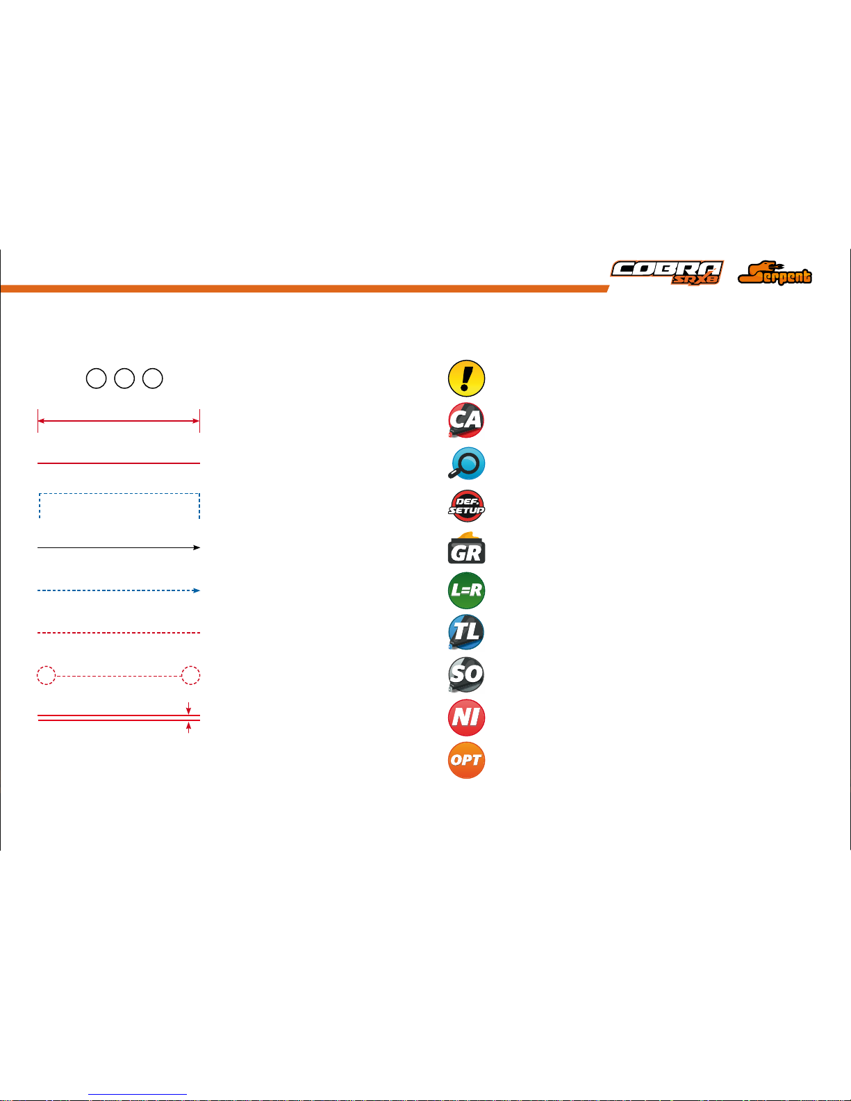
hOW TO USE ThE maNUal
Each step contains a variety of numbers, lines, and symbols. The numbers represent the order in
which the parts should be assembled. The lines are described below.
Each step contains a variety of symbols described below.
Assembly path of one item into another
Group of items (within lines) should be
assembled first
Direction the item should be moved
Glue one item to another
Press/Insert one item into another
Connect one item to another
Gap between two items
ICONS DESCRIpTIONlINES DESCRIpTION
Carefull, read and check very well.
Apply a small amount of cyano glue. Use wear protection for eyes and hands.
Detail view to explain assembly or order of parts better.
Default set-up: This symbol indicates the default setup.
Grease: apply a small amount of grease to the parts shown.
Left and right parts should be assembled in the same way.
Silicone oil: use the indicated silicone oil for the shocks and differentials.
Parts or items not included in the kit.
Optional part, not standard in the kit.
Thread lock: apply a small amount on the parts shown. Before to apply the threadlock,
make sure to degrease the parts very well, as otherwise the threadlock will not work.
Step number; the order in which you should
assemble the indicated parts
1 32
Length after assembly
Page 4

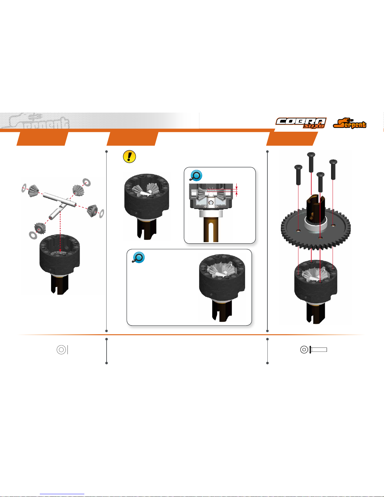
4
CENTER DIff aSSEmbly
6x11.75x0.2
6x11.75x0.2
8x16x5
8x16x5
M3x4
2.5x12
2.5x12
Use silicone oil to
hold seal in position.
STEp 1
CENTER DIff bag
1.1
1.2
3
1
2
8x16x5
6x11.75x0.2
2.5x12
M3x4
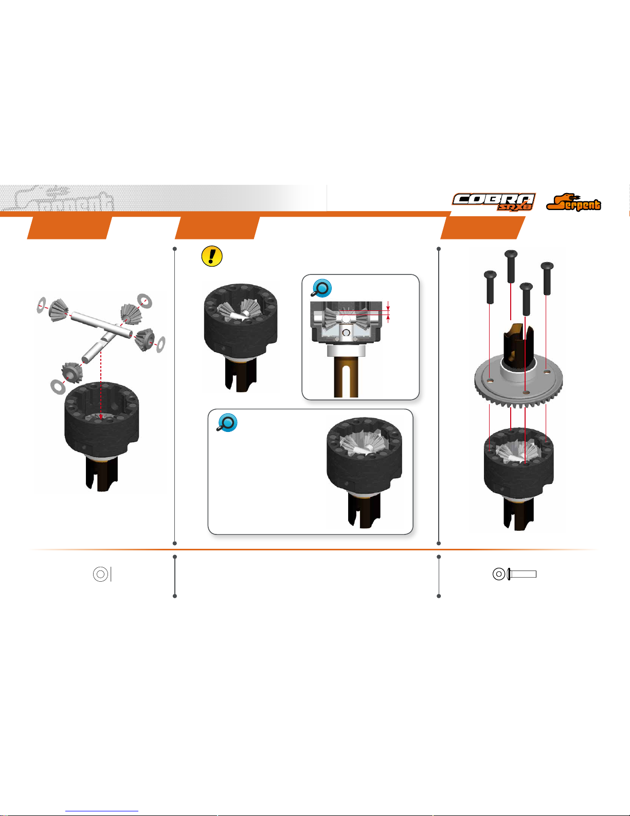
STEp 2
Add just enough oil to cover the large gear
before assembling the small satellite gears and
cross pins.
Use the silicone oil supplied in the kit. For the
correct cst value please check the default
setupsheet.
2.2
2.1
Note the correct
pin location.
Note the correct pin location.
14.7 - 14.9 mm
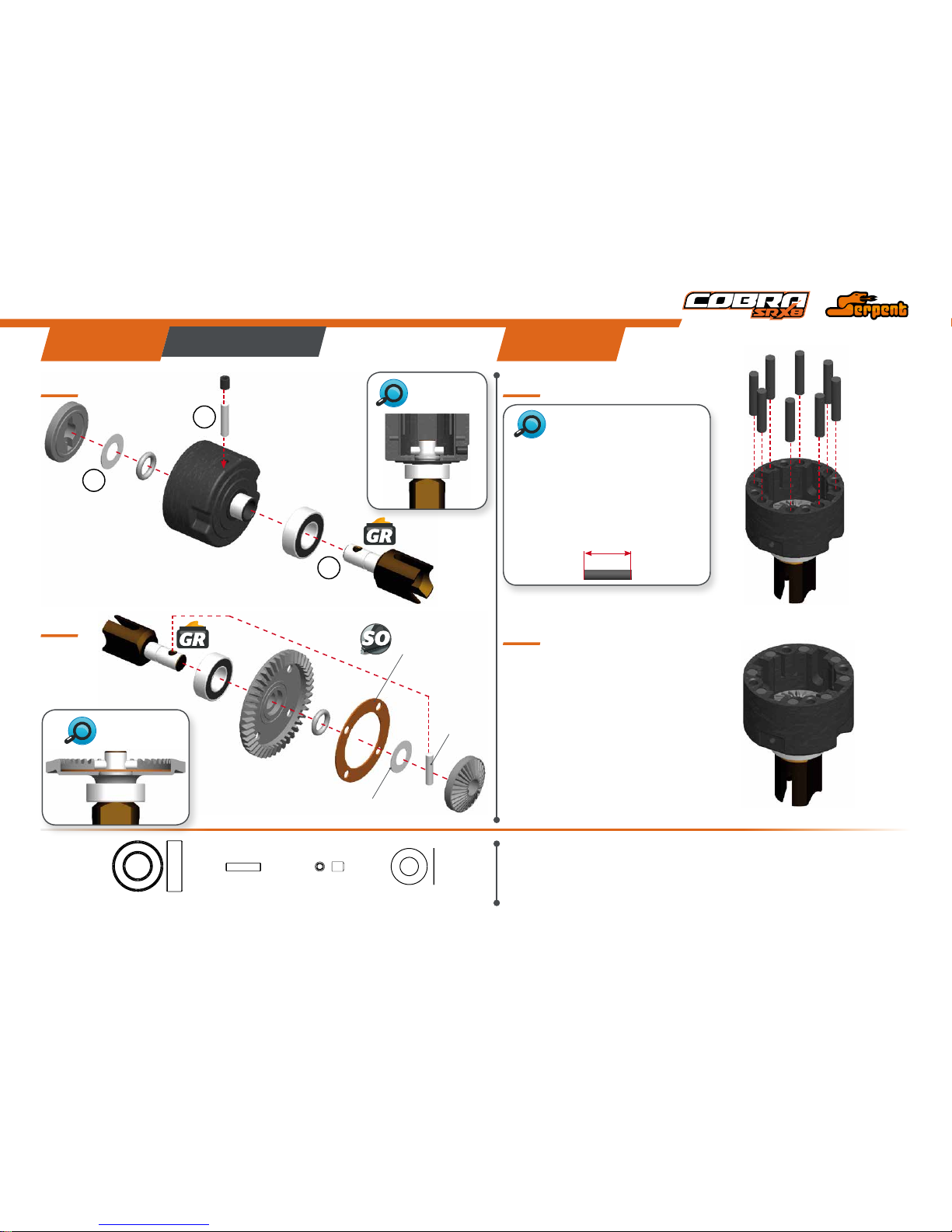
VOLUMECOMPENSATORS
When the differential gets hotter, the foam
inserts will absorb the pressure of the expansion
of the oil.
1- The supplied foam tube must be cut to size as
indicated here below.
2- Penetrate them fully with same differential oil .
3- Insert them in the compensator holes.
Page 5
5
STEp 4STEp 3 STEp 5
M3x14
3.5x7x0.1
M3x14
Fill the differential with silicone oil 1 mm above the crosspin, do NOT
overll. Use the silicone oil supplied in the kit. For the correct cst value
please check the default setupsheet.
Use a digital scale to measure the
exact amount of oil in the diff.
Differential weight with volume
compensators = 40.8 grams
Differential weight without volume
compensators = 41.0 grams
1mm
AMOUNT OF OIL IN
THEDIFFS
OILLEVEL
3.5x7x0.1
3.5x7x0.1
Page 6
6
fR/RR DIff aSSEmbly
STEp 6 STEp 7
fR/RR DIff bag
6x11.75x0.2
6x11.75x0.2
8x16x5
8x16x5
M3x4
2.5x12
2.5x12
Use silicone oil to
hold seal in position.
6.1
7.2
7.1
6.2
3
1
2
Add just enough oil to cover the large gear
before assembling the small satellite gears and
cross pins.
Use the silicone oil supplied in the kit. For the
correct cst value please check the default
setupsheet.
8x16x5
6x11.75x0.2
2.5x12
M3x4
Note the correct
pin location.
Note the correct
pin location.
14.7 - 14.9 mm
VOLUMECOMPENSATORS
When the differential gets hotter, the foam
inserts will absorb the pressure of the expansion
of the oil.
1- The supplied foam tube must be cut to size as
indicated here below.
2- Penetrate them fully with same differential oil .
3- Insert them in the compensator holes.
Page 7
7
STEp 9STEp 8 STEp 10
M3x14
3.5x7x0.1
M3x14
Fill the differential with silicone oil 1 mm above the crosspin, do NOT
overll. Use the silicone oil supplied in the kit. For the correct cst value
please check the default setupsheet.
1mm
Use a digital scale to measure the
exact amount of oil in the diff.
Differential weight with volume
compensators = 40.15 grams
Differential weight without volume
compensators = 40.35 grams
AMOUNT OF OIL IN
THEDIFFS
OILLEVEL
3.5x7x0.1
3.5x7x0.1
Page 8
8
CENTRal aSSEmbly
STEp 12STEp 11
bag 1
1
2
12.1
12.2
M3x16
Flanged
M3x6
M3x16 Flanged
M3x6
Front
Front
Front
Rear
Rear
Rear
Diff mounts are NOT symmetrical.
Please check below picture to
ensure front and rear bracket assembly are
assembled properly.
Do NOT overtighten
the screws.
Page 9
9
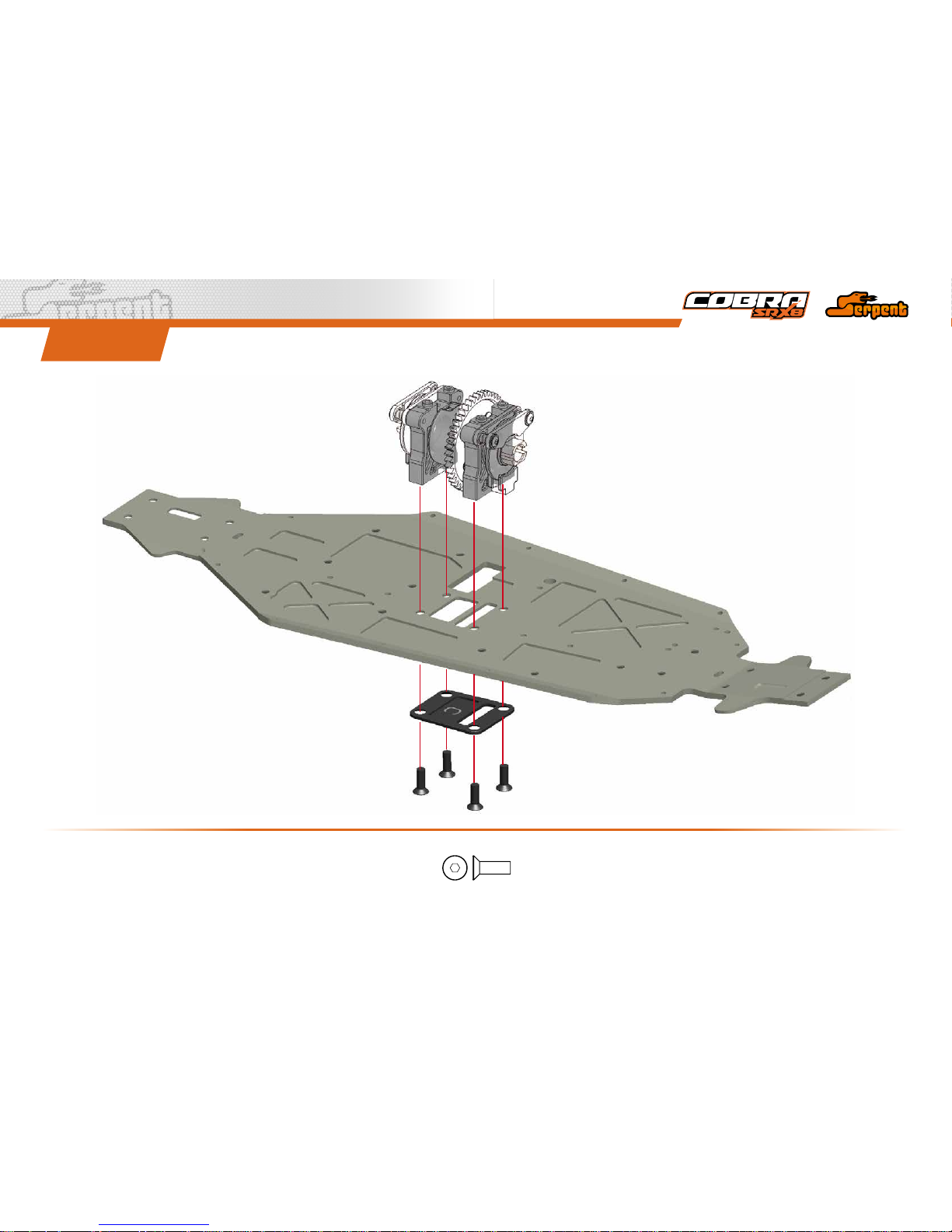
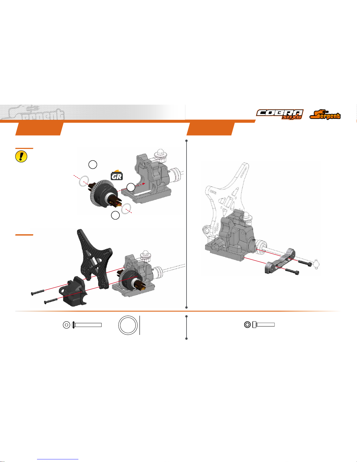
STEp 13
M4x12
M4x12
Page 10
10
STEp 14 STEp 15
14.1 14.2
M3x12
Nylock nut M3
3.2x7x0.5
M3x10
M3x4
M3x4
1
1
2
2
3
4
M3x12
3.2x7x0.5
Nylock Nut M3
M3x4
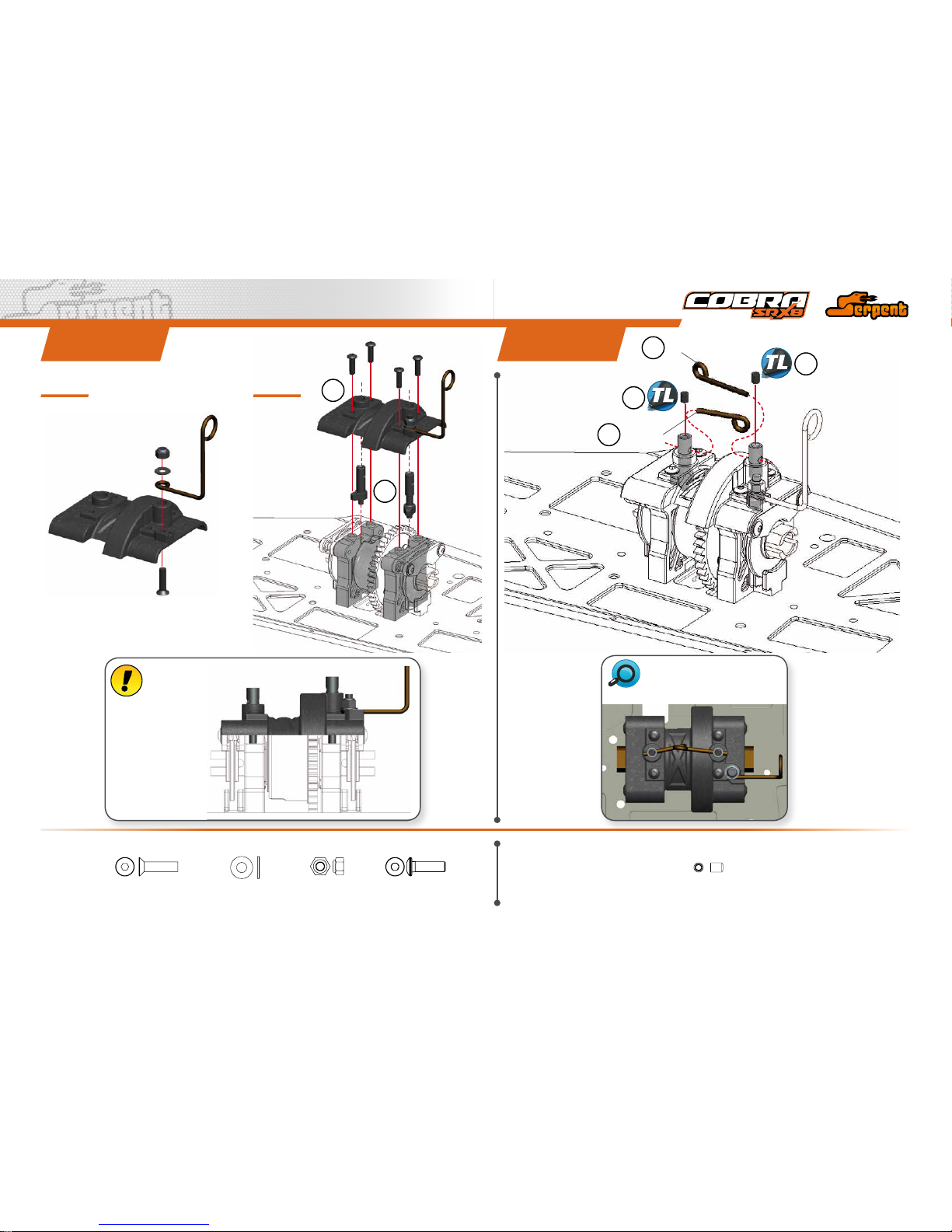
Note the correct brake wires
position.
M3x10
Front
Long
Short
Rear
FrontRear
The long cam is
assembled in the front
bracket, the short one
in the rear bracket .
BRAKE
CAMS
Page 11
11
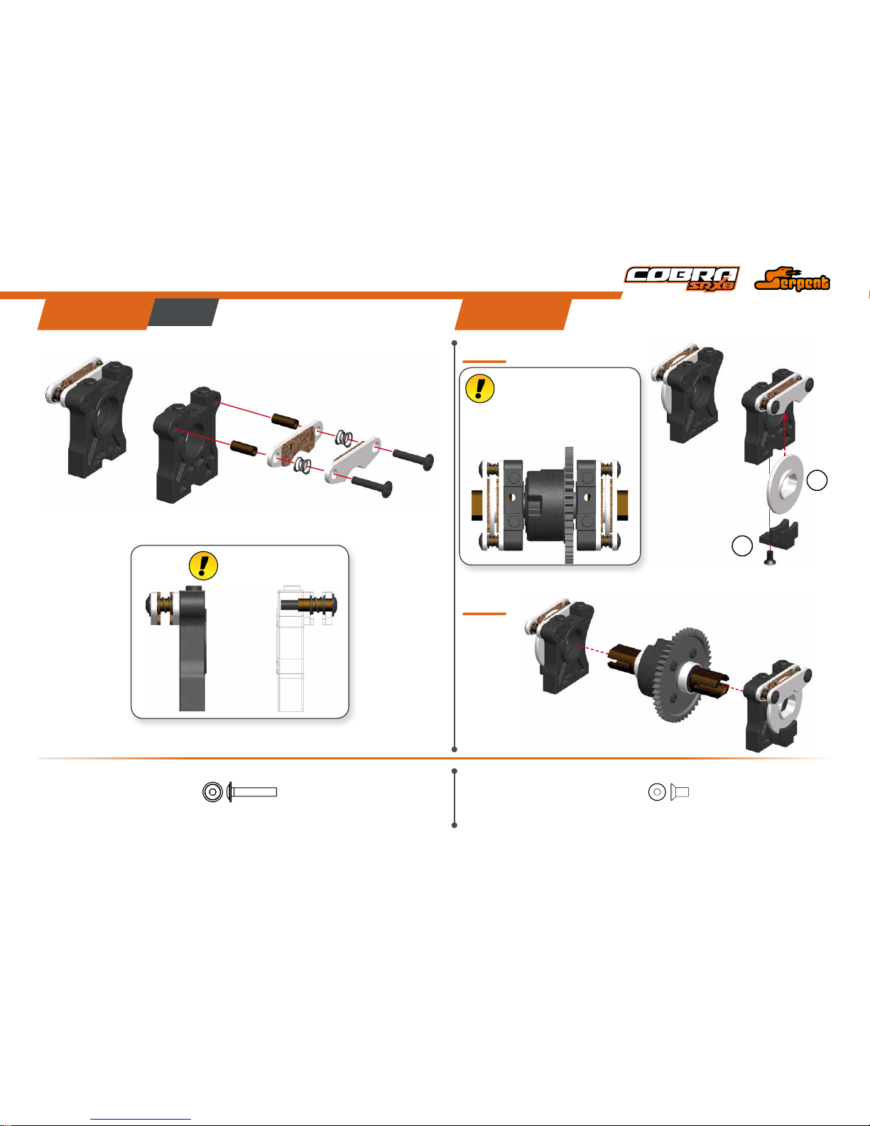
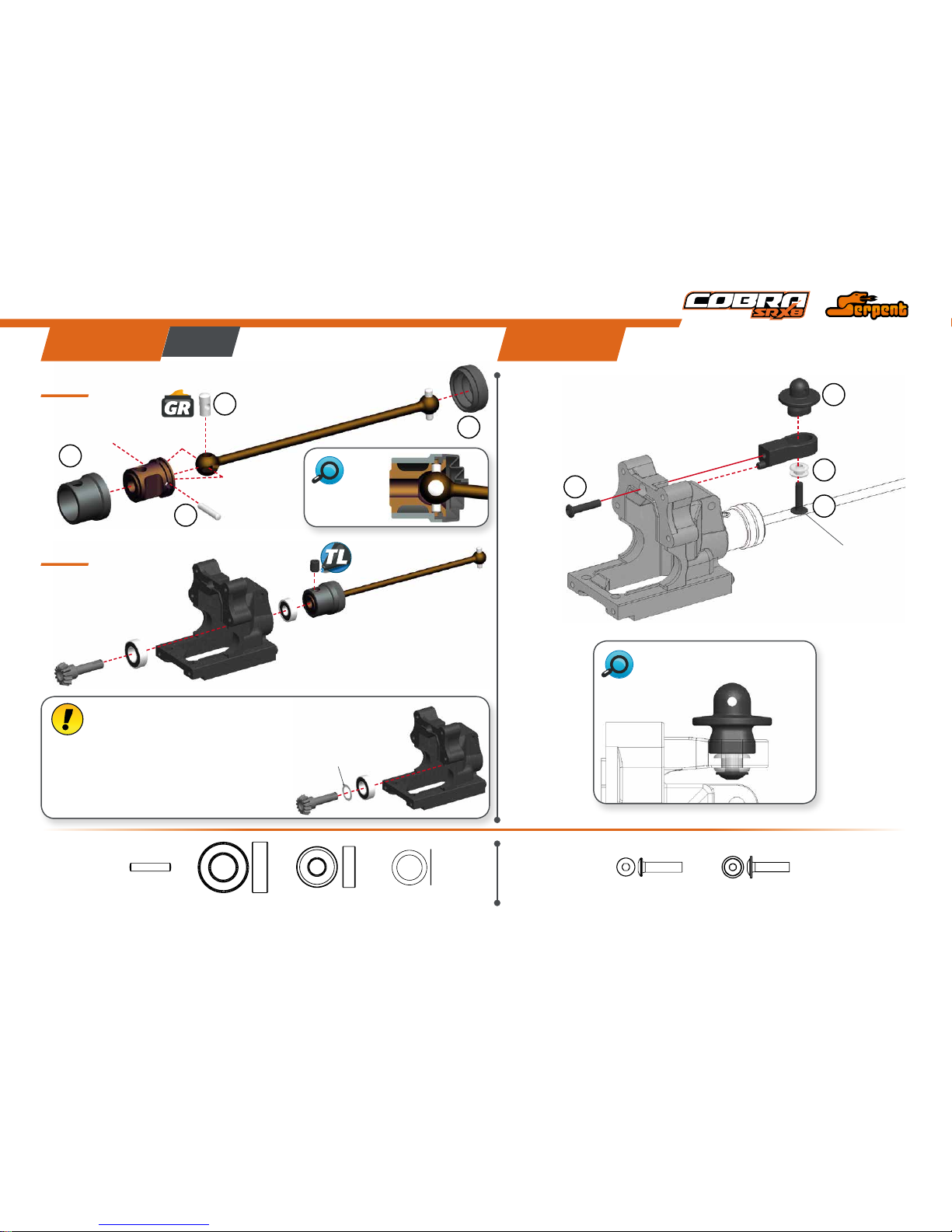
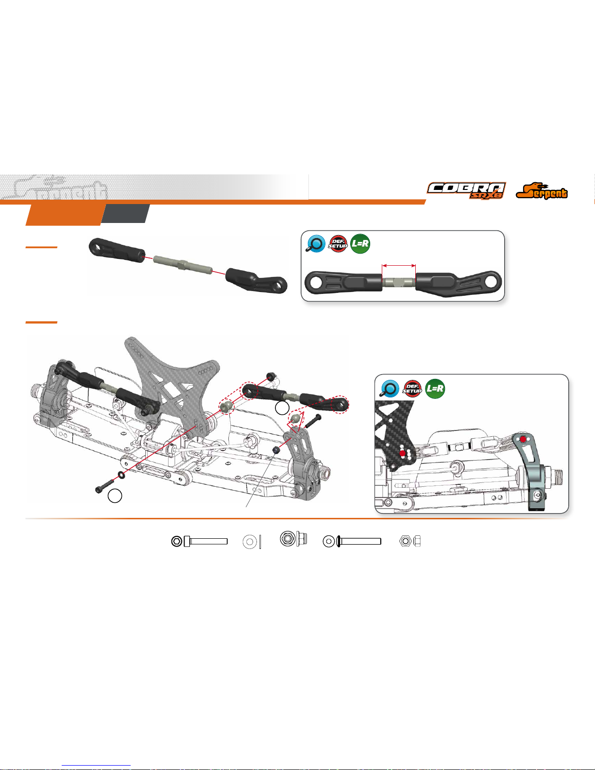
REaR aSSEmbly
STEp 16 STEp 17
Note the correct grommet position.
After building the differential with new gears, new dif ferential case
and bearings, the diff may feel a lit tle tight. The connected parts need
at least an hour run-time to create a per fect match. Attention: When
you assemble the diff with too much initial play, the gears will not run-in
properly and may wear quickly. After 1 or 2 hours of
running the car, re-check the gear-mesh between the
ring gear and the pinion. All parts should have run-in
properly n ow. You may add or remove 8x 11x0.1 shims
as needed.
16.1
16.2
1
2
3
4
2.5x13
8x16x5
8x11x0.1
5x13x4
M5x6
M3x14
M3x12
Flanged
1
2
2
3
8x11x0.1
2.5x13
8x16x5
5x13x4
M3x14
M3x12 Flanged
Note the correct
coupler assemby.
bag 2
Page 12
12
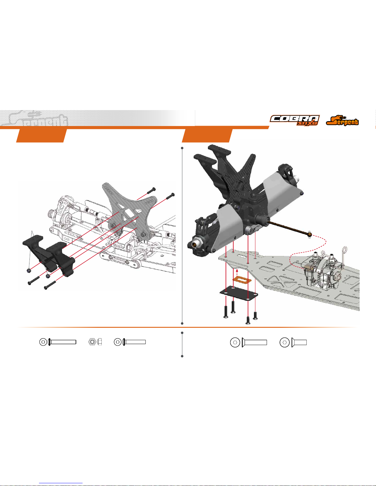
STEp 18 STEp 19
18.1
18.2
13x16x0.1
M3x22
13x16x0.1
2
1
1
M3X16
M3x22 M3x16
13x16x0.1
After 1 or 2 hours
of running the car,
re-check the gearmesh between the ring gear
and the pinion. All parts
should have run-in properly.
You may add or remove
13x16x0.1 shims as needed.
Page 13
13
2
3
4
1
M2.5X6
M2.5X6
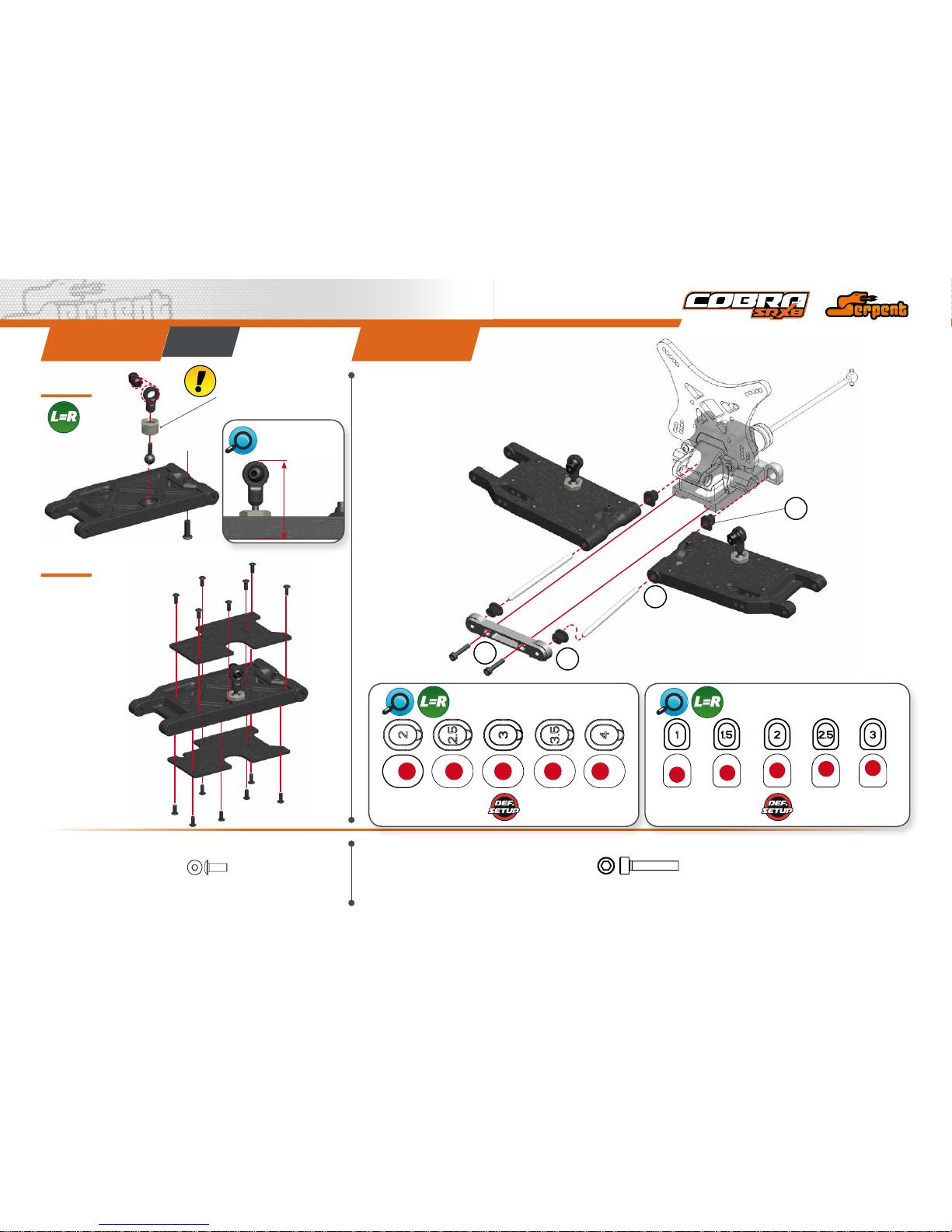
STEp 20 STEp 21
M3X16
20.1
20.2
REARTOEININSERTSCHART REARANTISQUATINSERTSCHART
M3x16
M2.5x6
bag 3
34 mm
ANTIROLL BAR
RODLENGTH
Tighten anti-roll bar cap until
there is no play, and it moves
freely.
Page 14

14
STEp 23STEp 22
REARANTIROLLBARASSEMBLY
Make correct holes in the
mudguards as required.
M3X3
M3X8
M3X8
M3X3
5X8X2.5
Flanged
M3x3
5X8X2.5 Flanged
M3x8
Page 15
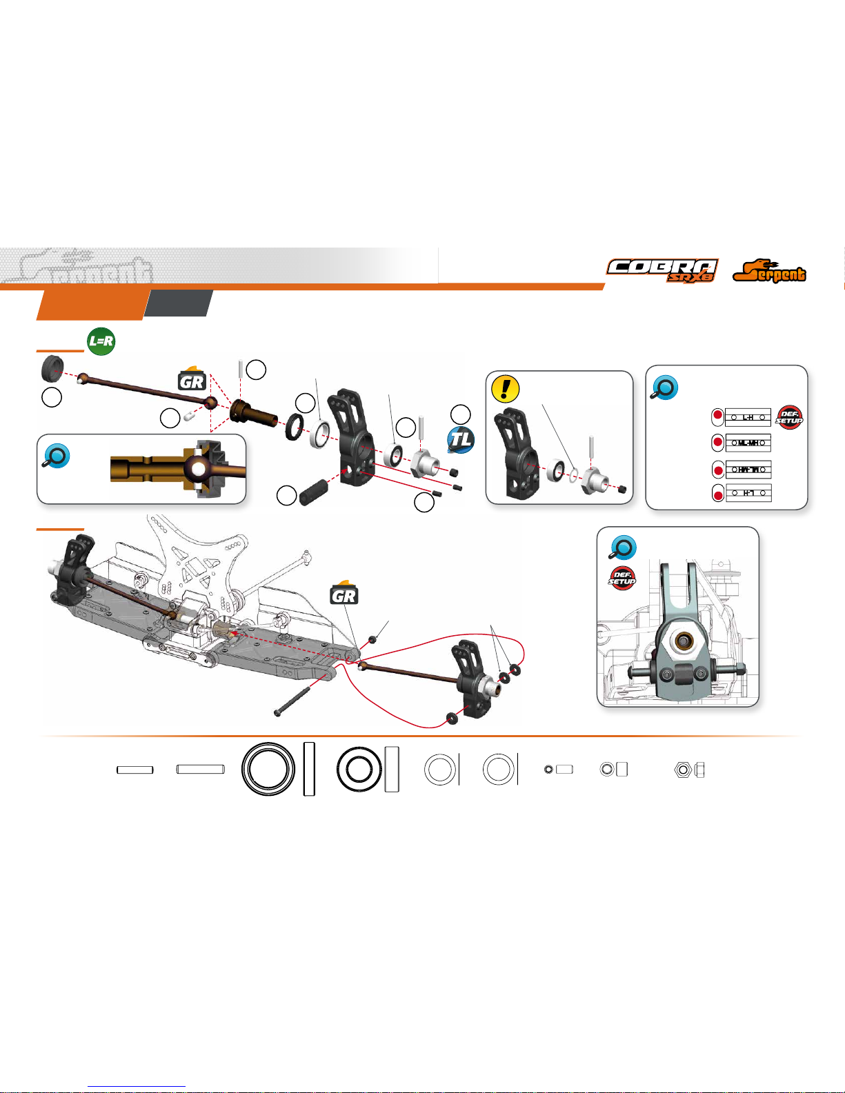
15
STEp 24
3x17
13x19x4
8x16x5
M3x6
2.5mm
1.25mm
Nylock Nut M3
M5x4
2.5x13
24.1
24.2
4
3
5
6
1
2
7
8
M3x6
2.5x13 3x17
Nylock Nut M3
8x16x5
13x19x4
M5x4
bag 4
Note the correct
coupler assemby.
REAR UPRIGHT ROLL
CENTERINSERTS CHART
LOW
MID LOW
MID HIGH
HIGH
REARDEFAULT
WHEELBASESHIMS
Apply shims s ize 8x11x0.1
and/or 8x11x0.2mm as
needed to remove play.
8x11x0.1
8x11x0.2
Page 16
16
25.1
25.2
STEp 25
M3X20
M3X20
3.2x7x0.5
Nylock Nut
M3 Flanged
Nylock Nut M3
1
2
M3x20 3.5x7x0.5
Nylock Nut M3
Nylock Nut M3
Flanged
M3x20
bag 5
17.7 mm
REARCAMBERLINKLENGTH
REARCAMBERLINK
DEFAULTPOSITION
Page 17
17
STEp 26
M3X25
M3X16
Nylock Nut
M3
STEp 27
M4x12
M4x20
Nylock Nut M3
M3x25 M3x16
M4x12M4x20
Page 18

18
fRONT aSSEmbly
28.1 29.1
28.2
29.2
1
2
4
3
2.5x13
8x16x5
8x11x0.1
5x13x4
M5x6
M3x22
M3x16
STEp 28 STEp 29
13x16x0.1
13x16x0.1
2
1
1
After building the differential with new gears, new differential
case and be arings, the diff may feel a lit tle tight. The conne cted
parts need at least an hour run-time to create a perfect match.
Attention: When you assemble the dif f with too much initial play, the
gears will not run-in properly and may wear quickly. After 1 or 2 hours
of running the car, re-check the gear-mesh
between the ring gear and the pinion. All parts
should have run-in properly now. You may
add or remove 8x11x0.1 shims as needed.
8x11x0.1
2.5x13
8x16x5
5x13x4
M3x22
13x16x0.1
M3x16
bag 6
After 1 or 2 hours
of running the car,
re-check the gearmesh between the ring gear
and the pinion. All parts
should have run-in properly.
You may add or remove
13x16x0.1 shims as needed.
Note the correct
coupler assemby.
Page 19

19
31.1 31.2
STEp 30 STEp 31
M2.5X6
M2.5X6
M3x16
M3x16
34 mm
M2.5x6
bag 7
ANTIROLL BAR
RODLENGTH
Tighten anti-roll bar cap until
there is no play, and it moves
freely.
Page 20

20
STEp 32 STEp 33
M3x16
M3x3
M3x3
5X8X2.5
Flanged
M3x16
M3x3
5X8X2.5 Flanged
FRONTANTIROLLBARASSEMBLY
FRONTSUSPENSION
KICKUPINSERTS
FRONTREAR
INSERTS
Page 21

21
STEp 34
34.1
3x17
13x19x4
8x16x5
M3x10
M5x4
2.5x13
4
3
5
6
7
1
2
M4x6
2.5x5x0.4
2.5x13
3x17
Nylock Nut M3
8x16x5
13x19x4
M5x4
M3x10
M2.5x6
M3x3
bag 8
Note the correct
coupler assemby.
3
2
Nylock Nut M3
1
M3x3
34.334.2
M4x6
M2.5X6
2.5x5x0.4
M4x6
4
1
3
2
2
3
Align the at spot
on the shaft with the
grubscrew.
Steering arm 1 is
included in the kit.
STEERINGARMS
Apply shims size 8x11x0.1 and/
or 8x11x0.2mm as needed to
remove play.
8x11x0.1
8x11x0.2
Page 22

22
35.1
35.2
STEp 35
M3x20
M3x20
3.2x7x0.5
Nylock Nut
M3 Flanged
Nylock Nut M3
1
2
M3x20 3.5x7x0.5
Nylock Nut M3
Nylock Nut M3
Flanged
M3x20
bag 9
16.7 mm
FRONTCAMBERLINKLENGTH
FRONTCAMBERLINK
DEFAULTPOSITION
Page 23

23
STEp 36
M4x20
M4x12
M4x12M4x20
Page 24

24
STEERINg aSSEmbly
STEp 37 STEp 38
38.1
38.2
1
1
2
M4x8
M2x10
M3x12
3x6x0.5
3x6x0.5
M3x12
M4x10
The servo saver spring
should be preloaded
4.5mm. Also notice the
correct orientation of the
collar.
Nylock Nut M3
4.5 mm
M4x8M4x10
M2x10
M3x12
3x6x0.5
Nylock Nut M3
bag 10
Page 25

25
STEp 39
STEp 40
6x10x3
6x10x3
3x7.5x1
Conical
3x7.5x1
Conical
3x7.5x1
Conical
3x7.5x1
3x7.5x1
M3x18
M3x18
M3x20
M3x20
Note correct
position of the
conical shim.
Note correct position
of the conical shim.
Note correct orientation of
the outer steering balljoints.
Nylock Nut M3
Nylock Nut
M3 Flanged
Nylock Nut
M3 Flanged
1
1
2
2
39.1
39.2
11 mm
3x7.5x1 Conical
6x10x3
M3x18
M3x20
Nylock Nut M3
3x7.5x1 Conical 3x7.5x1
Nylock Nut M3
Flanged
STEERINGTRACKRODLENGTH
Page 26

26
STEp 41 STEp 42
M4x12
M3x12
M4x30
M4x10
M3x14
M3x10
M3x12
Nylock Nut M3
Nylock Nut M3
Nylock Nut
M4 Flanged
1
1
1
1
2
2
2
2
3
3
M3x12 M3x10 M3x14
Nylock Nut M3
Nylock Nut M3
M4x10 M4x12
M3x12
M4x30
Nylock Nut M3
Flanged
bag 11
Page 27

27
STEp 43
M3x6
M3x6
M3x6
Put thread lock in all the M3x6 screws
that x the side guards to the chassis.
Page 28

28
RaDIO aSSEmbly
STEp 44
44.1
44.2
M3x8
M3x16
Flanged
M3x16
Flanged
Nylock Nut M3
3x7.5x1 Conical
3x7.5x1 Conical
Nylock Nut M3
1
1
2
M3x8
M3x16 Flanged
bag 12
19.3 - 19.6 mm
STEERINGLINKLENGTH
Note correct
position of the
conical shim.
STEp 45
Use enough servo spacers so both servos are ush with the bottom of the radiotray
posts. This will prevent the servo to touch the chassis under torsion – ex.
SERVOSPACERS
Between differnet servo brands
there could be slight differences.
Check how many teeth your
servo spline has (23, 24 or
25) and use the right lever.
Page 29

29
STEp 47
Assembly detail in case of using a larger transponder.
M2x10
M3x5
M3x5
M2x10
M2x10 M2x10
M3x5
STEp 46
Assembly detail in case
of NOT using a switch.
M2x10
Page 30

30
STEp 48 STEp 49
48.1
48.2
M2x10
M4x12
M4x12
M4x12
M2x10
M2x10
M3x4
3x7.5x1
Conical
1
1
2
2
Nylock Nut M3
M2x10 M3x4
3x7.5x1 Conical
M4x12
Nylock Nut M3
Apply the supplied decal
on the battery cover.
Apply the supplied decal
on the receiver cover.
Page 31

31
STEp 50 STEp 51
M3x3
M3x8
3.5x7x0.5
M3x5
M3x3
M3x3
M3x12
M3x8
THROTTLE/BRAKE
ASSEMBLY
THROTTLE/BRAKESPOKELENGTHS
Cut the spoke at the non threaded side
THROTTLEASSEMBLY
Note the correct
orientation of the
brake balls .
M3x12
M3x3
M3x3
M3x5
M3x3
3.5x7x0.5
1
2
2
3
4
5
5
6
4
46 mm
THROTTLE
65 mm
BRAKE
Check how many teeth
your servo spline has
(23, 24 or 25) and use
the right lever.
Page 32

32
ShOCKS aSSEmbly
STEp 52 STEp 53
52.1
53.1
53.2
52.2
52.3
1
2
Use some silicone oil
during the assembly.
Use some silicone oil
during the assembly.
Insert the o-ring
inside the spring
collar.
Nylock Nut M2.5
2.5x6x0.5
2.5x6x0.5
Nylock Nut M2.5
bag 13 fR ShOCKS / bag 14 RR ShOCKS
Note the correct
orientation of the
shock spacers .
Note the correct
position of the
o-ring .
Page 33

33
STEp 54
STEp 55
54.1
54.2
54.3
SHOCKSLENGTH:Measure the
shock length fully extended.
Push the membrane
into the shock cap.
FRONT REAR
36.5
mm
44
mm
1- Fill up with sillicone oil
fully using the silicone
oil supplied in the kit.
For the correct cst value
please check the default
setupsheet.
2- Extend the shockrod fully
3- Move the shockrod
slowly up and down
to let ALL air bubbles
escape.
4- Close top only 3/4.
1-Bleed: push the
shockrod all the way
in slowly, to allow
excessive oil to escape.
2- Close completely the
shock cap.
Assemble the spring and springcup (align correctly) to complete
the shock.
Page 34

34
STEp 56 STEp 57
M3x6
M3x6
M3x6
M3x6
M3x25
M3x25
Nylock Nut
M3 Flanged
Nylock Nut
M3 Flanged
1
2
2
3
3
Nylock Nut M3
Flanged
Nylock Nut M3
Flanged
M3x6
M3x6
M3x25 M3x25
1
3
3
2
2
FRONTSHOCKS
DEFAULTPOSITION
REARSHOCKS
DEFAULTPOSITION
Page 35

35
fINal aSSEmbly
STEp 58
58.1 58.3
58.2
M3x18
M3x12
M3x12
M3x16 Flanged
M2x6
M2x6
M2x6
Nylock
Nut M3
M2x6
M3x18
Nylock Nut M3
M3x12
M3x16 Flanged
bag 15
M3x14
M3x14
The fuel-tank features a premounted 3cc insert.
You can remove it if needed as shown.
FUELTANKINSERTS
Page 36

36
ClUTCh aND ENgINE aSSEmbly
M3x14
M3x14
STEp 59 STEp 60
59.1
59.2
5x8x0.1
5x8x0.3
M3x8
3.2x7x0.5
5x10x4
3.2x7x0.5
5x8x0.1 5x8x0.3
5x10x4
M3x8
M3x14
Push the long leg of the
spring in the inner hole
of the clutch shoe.
Do not fully tighten the M3x14 screws till Step 61.
bag 16
Page 37

37
STEp 61 STEp 62
M4x10
M5x4
M3X8
M4x10
M5x4
M3x8
If the engine used is an OS (or OS
based engines like Mx), Alpha and SH,
it might be needed to trim off some
plastic from the center diff cover to give
the carburetor enough clearance over
the brake plates. This could be done
with a hobby knife.
1- Assemble and fully tighten the M4x10 screws.
2- Position the engine in such way on the engine
mount that the gearmesh is correct.
3- Fully tighten M3x14 screws assembled during the
Step 60.
Page 38

38
STEp 63
Page 39

39
STEp 65
1
2
STEp 64
64.2
64.1
ANGLEDWING
SPACERSCHART
AIRFILTERASSEMBLY
1
2
3
M3x18
M3x6
M3x6
Body Clip
M3x18
2º
4º
6º
Oil the airlter with a high quality foam-airlter
oil ( not included). Do NOT use silicone oil.
Use tie raps to x the the air lter boot
to the airlter and to the carburator.
bag 17
FRONTREAR
Page 40

40
STEp 66
Page 41

41
STEp 67
M3x5
M3x5
1- Cut the body along the cutting line with special
scissors (not included). Make holes for the
bodypost and antenna as needed with a body
reamer (not included). Make a longer bodypost
hole in the rear, to allow for chassis ex movement.
2- Before painting the body, apply the precut
masking sheet elements to the inside of the
body. Follow the cleaning & painting instructions
supplied by the polycarbonate paint supplier you
choose.
3- Apply the Serpent and Cobra logo-decals on
the body and wing.
Body Clip
1
2
3
3
Page 42

EXplODED VIEWS
42
INDEX
DIffERENTIalS EXplODED VIEW 42
CENTRal EXplODED VIEW 43
REaR EXplODED VIEW 44
fRONT EXplODED VIEW 45
STEERINg EXplODED VIEW 46
RaDIO EXplODED VIEW 47
ShOCKS EXplODED VIEW 48
ClUTCh EXplODED VIEW 49
fINal 1 EXplODED VIEW 50
fINal 2 EXplODED VIEW 51
Page 43

DIffERENTIal EXplODED VIEW
43
600726
600147
600213
600213
110454
600209
600283 opt
600421
600421
110207
110207
110 111
1396
1396
600200
600200
600831
110115
600727
600727
600728
600376
600376
600813
600814 opt
600815 opt
600283 Diff pin 10T alu (2)
600814 Spur gear 47T SRX8
600815 Spur gear 48T SRX8
600868 Diff set 44T front / rear SRX8
600869 Diff set 46T center SRX8
Page 44

44
CENTRal EXplODED VIEW
600721
600742
600747
600742
600745
600746
110115
110127
110109
600746
110115
110109
110402
110401
600742
110105
600808
110122
110122
600743
600743
110146
110146
600748
600748
600744
600744
600829
600829
Page 45

45
REaR EXplODED VIEW
600722
600738
600739
110191
110105
600834
110211
110211
600197
600197
600477
600174
600193
600485 opt
600774
600837 opt
600108
600189
600776
600225
110124110402
110402
600185
110224
1396
600774
600777
600365
600778
1393
110140
600820
600851 opt
600852 opt
110137
110148
600780
600102
600729
1070
600730
600847 opt
600725
110431
110431
110432
1396
1340
110145
600735
110402
110141
110142
110107
600823
600722
600733
600733
600734
600873
110121
600732
600853 opt
600770
600781
110116
110116
110116
600238 opt
600434 opt
600239 opt
600684 opt
600237
600339 opt
600338 opt
803134
110401
110 111
803134
600484 opt
600484 opt
1312
1312
600192
600622 opt
600828
600794
110441
110110
110130
110130
600823
110193
600795
110107
600338 Antiroll bar rear 1.8mm
600339 Antiroll bar rear 2.0mm
600434 Antiroll bar rear 2.4mm
600238 Antiroll bar rear 2.5mm
600239 Antiroll bar rear 2.7mm
600684 Antiroll bar rear 3.0mm
600484 Antirollbar spacer 3mm alu (2)
600485 Pivotball threaded anti roll bar alu (2)
600622 Pivotball antirollbar alu (4)
600837 Wishbone insert carbon RR (2+2)
SRX8
600838 Upright weight brass 15gr (2) SRX8
600847 Shocktower RR alu SRX8
600851 Wheelhexagon 0mm light (2) SRX8
600852 Wheelhexagon +1mm light (2) SRX8
600853 Gear coupler alu SRX8
Page 46

46
fRONT EXplODED VIEW
600775
600834
600108
600793
600723
600723
600725
600731
600795
600732
600102
600102
600873
600733
600733
600736
110141
600741
600737
600794
110441
600780
600781
600783
600782 opt
600788 opt
600784 opt
600790 opt
600791 opt
600792 opt
110440
110116
110119
110130
110130
600836 opt
110130
600785
110224
110148
1396
110109
1393
600786
600786
600787
600789
600821
600851 opt
600852 opt
600823
600823
600828
110107
600240
600241 opt
600242 opt
600337 opt
600336 opt
600225
110402
600174
600193
110211
600197
600197
110191
110105
110116
600192
110401
110140
110402
110110
110193
110431
1396
1340
110116
110116
803134
803134
1312
600185
110121
600622 opt
600485 opt
600484 opt
600336 Antiroll bar front 1.8mm
600337 Antiroll bar front 2.0mm
600241 Antiroll bar front 2.5mm
600242 Antiroll bar front 2.7mm
600484 Antirollbar spacer 3mm alu (2)
600485 Pivotball threaded anti roll bar alu (2)
600622 Pivotball antirollbar alu (4)
600782 C-hub 13deg L+R alu SRX8
600784 C-hub 17deg L+R alu SRX8
600788 Steering arm 0 carbon (2) SRX8
600790 Steering arm 2 carbon (2) SRX8
600791 Steering arm 3 carbon (2) SRX8
600792 Steering arm 4 carbon (2) SRX8
600836 Wishbone insert carbon FR (2+2)
SRX8
600846 Shocktower FR alu SRX8
600851 Wheelhexagon 0mm light (2) SRX8
600852 Wheelhexagon +1mm light (2) SRX8
600853 Gear coupler alu SRX8
110211
600853 opt
600846 opt
110431
110432
Page 47

47
STEERINg EXplODED VIEW
600724
600750
1321
1321
600167
600751
600751
600764
110101
110188
110102
600827
600751
600178
600178
110441
110441
110439
110159
600749
600749
110402
110405
110402
110127
110127
110402
110402
110184
600754
600724
110108
110108
110108
110108
600729
110105
110183
110102
110102
600752
600753
600170
600812
600330
110112
600180
110125
110125
600830
110192
600178
110439
600844 Transmission brace alu FR SRX8
600845 Transmission brace alu RR SRX8
600844 opt
600845 opt
Page 48

48
RaDIO EXplODED VIEW
600764
600227
600227
401355
110402
110402
600757
600757
600757
110149
110188
110188
1606
600757
110115
110105
110105
600759
600292 opt
600843 opt
600291 opt
600842 opt
600290 opt
600841 opt
110152
600760
110152
110127
110401
110128
600761
600761
804181
600333
600333
600761
600763
600763
600761
600762
110116
110116
110116
1639
1639
1639
600762
600761
600757
110146
110146
600757
110128
600757
600106
600178
600178
600290 Servo lever steering 23T alu
600291 Servo lever steering 24T alu
600292 Servo lever steering 25T alu
600841 Servo lever throttle alu 23T SRX8
600842 Servo lever throttle alu 24T SRX8
600843 Servo lever throttle alu 25T SRX8
600758 Radio + battery box skin carbon look SRX8
Page 49

49
ShOCKS EXplODED VIEW
600796
600818
110456
110438
600822 FR / RR
600797
600802
600803
600113
600111
600347
600158
600804
600805
600646 opt
600648 opt
600800 FRONT
600798 FRONT
600650 opt
600652 opt
600654 opt
600656 REAR
600647 opt
600649 opt
600651 FRONT
600653 opt
600655 opt
600801 REAR
600799 REAR
600657 opt
600816 opt
600817 opt
600848 opt
600850 opt
600875 opt
600849 opt
600646 Shockspring FR orange V2 (2)
600647 Shockspring FR red V2 (2)
600648 Shockspring FR blue V2 (2)
600649 Shockspring FR purple V2 (2)
600650 Shockspring FR green V2 (2)
600658 Shockspring set FR V2 (6x2)
600652 Shockspring RR orange V2 (2)
600653 Shockspring RR red V2 (2)
600654 Shockspring RR blue V2 (2)
600655 Shockspring RR purple V2 (2)
600657 Shockspring RR green V2 (2)
600659 Shockspring set RR V2 (6x2)
600357 Membrane webbed silicone (4)
600816 Shock piston blank (4) SRX8
600817 Shock piston 5 holes (4) SRX8
600819 Shock piston 8 holes (4) SRX8
600848 Shock shaft FR TiN coated (2) SRX8
600849 Shock shaft RR TiN coated (2) SRX8
600850 Shock cap pro hard coated (2) SRX8
600870 Shock set Pro front (2) SRX8
600871 Shock set Pro rear (2) SRX8
600875 Shock top gasket (4) SRX8
Page 50

50
ClUTCh EXplODED VIEW
1315
1315
600206
110423
110424
600163
600228
600262
110152
110401
600232 opt
600231opt
600175 opt
600355 opt
600298 opt
600230
600229 opt
600518 opt
600519 opt
600217 opt
600216
600233 opt
600518 Clutch bell 13T vented
600217 Clutch bell 14T
600519 Clutch bell 14T vented
600229 Clutch spring soft 0.85mm (4)
600231 Clutch spring hard 0.95mm(4)
600232 Clutch spring X hard 1mm(4)
600233 Clutch spring set (4x4)
600175 Clutchshoe alu (4)
600355 Clutch shoe set Alu / Carbon (2+2)
600244 Clutch-set alu / carbon
600298 Flywheel steel
Page 51

51
fINal 1 EXplODED VIEW
600755
110178
110178
600766
110144
600767
600115
600767
110195
110146
110402
600768
600835
600282 opt
600282 opt
600839 opt
600765
600768
600779
600824
110102
110127
110137
600824
600824
600824
600779
600779
600769
110194
110194
600769
600832
600835
110441
110441
110137
600282 Shock-pivot bushing delrin (4)
600839 Motormount mono alu SRX8
Page 52

52
fINal 2 EXplODED VIEW
600718
110157
600740
110104
1601
1601
1601
110148
600773
600756
600243
600340
600243
110108
600771
600825
600833
600301 opt
600143 opt
600277 opt
600439 opt
600440 opt
600826 opt
600840 opt
600872 opt
600263
110159
600772
600222
600297 opt
600620 opt
600719 opt
600621 opt
600297 Wheel-nut17mmanged/light(4)
600143 Wing white nylon
600277 Wing black nylon
600439 Wing white low 811
600440 Wing black low 811
600719 Body SRX8 High Downforce
600826 Wing straight MD white 1/8
600840 Wing lexan HD with gurney 1/8
600872 Wing gurney
600620 Rim 1/8 buggy White (4)
600621 Rim 1/8 buggy Yellow (4)
Page 53

SERPENTMERCHANDISING www.serpent.com/product/Merchandising/
TEam SERpENT NETWORK
SRX8SPAREPARTS www.serpent.com/600017/spares/
SRX8OPTIONALSPARTS www.serpent.com/600017/Optionals/
SERPENTTOOLS www.serpent.com/product/Tools/
Page 54

SERPENTWEBSITEANDBLOG
SERPENTSOCIALMEDIA
www.facebook.com/SerpentMRC
www.serpent.com
www.teamserpent.com
www.dragon-rc.com
www.youtube.com/user/SerpentMRC
www.twitter.com/SerpentMRC
www.plus.google.com/+SerpentModelcars/posts
www.weibo.com/teamserpent
SERPENTPROMOPAGES http://promo.serpent.com
SERPENTFACEBOOKGROUPS http://promo.serpent.com/indexfb.htm
SERPENTADVANCEDMANUALS http://promo.serpent.com/sam/
Page 55

Page 56

Manual Cobra SRX8 #82806-1
 Loading...