


1
SPYBALL® 6829 Alarm + Immobiliser
Thatcham cat. MC1
SPYBALL® 6809 Alarm Upgrade
Thatcham cat. MC2>1
Meeting The British Insurance Industry’s
Criteria for Motorcycle Security
USER INSTRUCTIONS
Thank you for choosing Spyball by Cobra. We recommend you read this guide carefully
and keep it for future reference.
VEHICLE SECURITY

2
Table of contents
1. Kit composition
2. Features of the radio transmitter
2.1.
Realignment of a transmitter
2.2.
Pairing of new transmitters
3. Biker Recognition function
3.1.
Selection of the Biker Recognition function
4. Arming / disarming of the security system
4.1.
Passive arming / disarming of the engine immobiliser (applies only to model 6829)
4.1.
Arming / disarming of the full security system without Biker Recognition function
(use as a conventional transmitter)
4.2.
Arming / disarming of the full security system with Biker Recognition function
5. Protection functions
6. Temporary deactivation of the movement sensor
7. Adjustment of movement detection sensitivity (this is a dealer operation)
8. Alarm cycle
8.1.
Reduction of audible alarm power
8.2.
Check control function
9. Alarm memory and diagnostics
10. Anti-hijack function
11. Back-up battery supply
12. Service Mode
13. “Turn indicator on” audible warning signal
3
14. Selectable functions – Enabling and disabling procedures
15. Automatic timed switch-off function (sleep function)
16.
Emergency disarming via PIN code
16.1.
Reading the PIN code
16.2.
Changing the PIN code
17. Troubleshooting guide
18. Technical data
1. KIT COMPOSITION
The kit includes
A control unit with its protective metal shield
Two remote control transmitters with Biker Recognition function
A set of fitting accessories and a wiring harness
A user manual (This is not a DIY product. Fitting instructions are available for download
from the professional installer area of the Cobra website www.cobra-at.com)
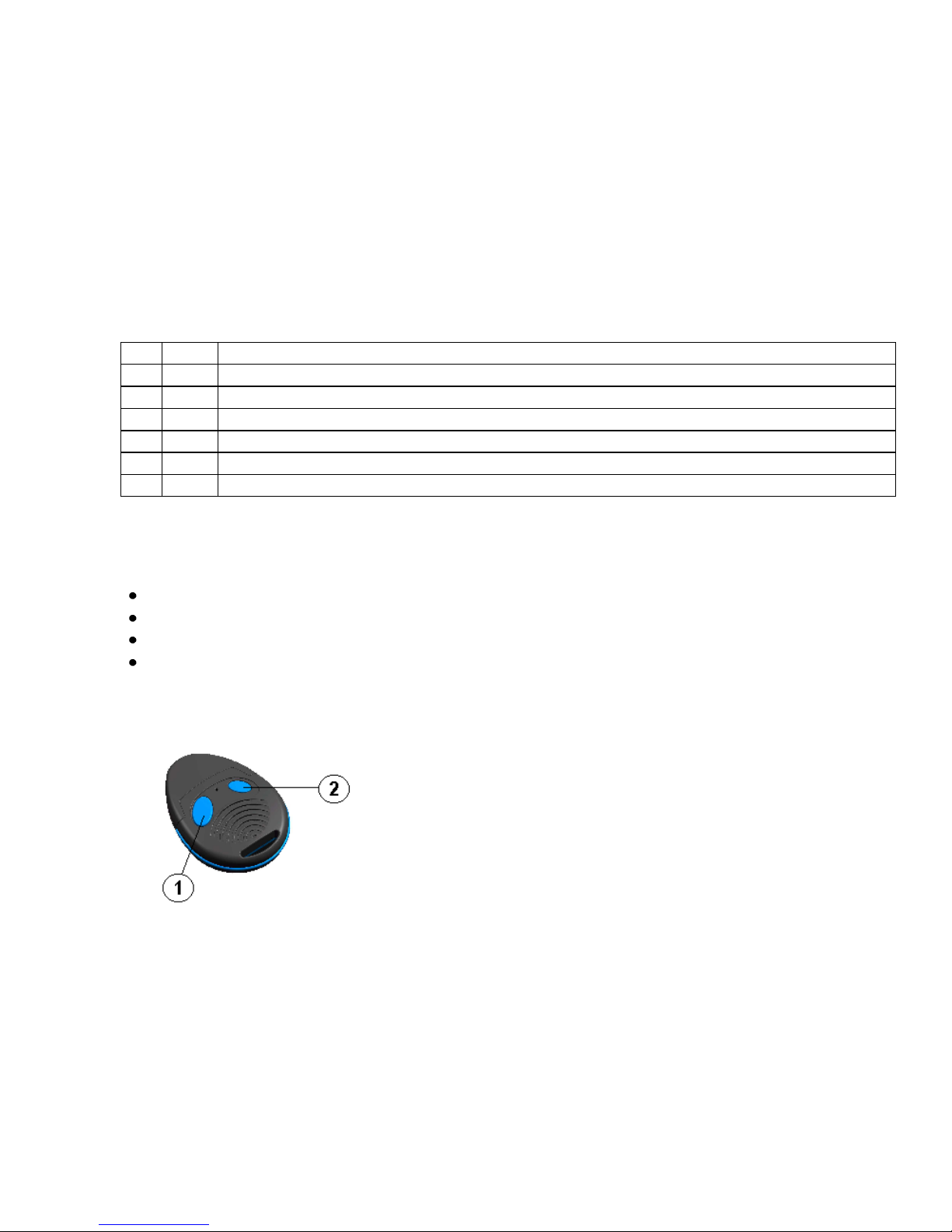
2. FEATURES OF THE RADIO TRANSMITTER
The radio transmitter (p/n 8742) has two buttons with different
functions and a small LED in the middle, that flashes during
transmission. It is protected against the use of code scanners
and grabbers.

4
It is powered by a Lithium CR 2032 3V-battery. When the battery is close to flat, the user is
warned by an additional flash of the turn indicators upon disarming.
Replace it as soon as possible and dispose of it at the appropriate collection points. Do not
delay the replacement of the battery, especially if you are using the Biker Recognition function,
because the system activates automatically when it does not receive any signals from the
transmitter!
Remark: to ensure good contact, take the new battery out of its packaging and place it into the
transmitter without touching it directly with your fingers (use a soft cloth).
2.1.Realignment of a transmitter
The transmitters that come with the kit are paired in advance and are already operational.
Realignment is needed when a paired transmitter is de-synchronised from the receiver.
This can happen if for example the transmitter is operated repeatedly outside the range of the
receiver because the transmitted code changes every time the alarm is turned on/off thanks to
an advanced method of random encryption (anti-scanning / anti-grabbing protection).
To realign, just press and hold down push-button n. 1 of the transmitter for at least 7 seconds.
A sequence of flashes of the turn indicators will confirm the success of realignment. If the
system is armed, it will disarm.
2.2. Pairing of new transmitters
In the event of loss of failure, one or two new transmitters can be paired as follows:
If the security system is armed, disarm it with the remaining transmitter (if it is available)
or enter your emergency disarming PIN code (see procedure in paragraph 16).

5
Turn ignition on and wait 20 seconds. The dashboard LED illuminates and remains
on about 3 seconds.
Before the dashboard LED extinguishes, turn ignition off and then on again. A short
and sharp sound signal confirms that the system is ready for pairing. The LED switches
off. You have 6 seconds to complete the operation as described below.
Press push-button n. 1 of a transmitter (or press both transmitters in turn, if you want to
pair two). The LED illuminates shortly, to confirm that pairing has been successful.
Once the operation is completed, turn the ignition off. If the ignition remains on, the
system will automatically quit the pairing procedure In both cases the exit from the
procedure is confirmed by a short sharp audible signal.
Important:
1) For security reasons, each system can accept a maximum of two remote
transmitters.
2) Every pairing procedure disables the transmitters which the receiver had previously
been paired with. Therefore: if you have lost a transmitter and you wish to pair a
spare one, do not forget that the one which has remained in your possession has to
be re-paired too (or it will stop working). If you are not able to acquire a replacement
transmitter quickly, then simply repeat the process to re-pair your existing
transmitter, and this will disable the missing transmitter.

6
3. BIKER RECOGNITION FUNCTION
Besides its operation as a conventional remote control key, the transmitter can be used in
Biker Recognition mode.This function is selectable.
When the Biker Recognition function is enabled, the transmitter sends a coded signal at
regular intervals (1.5 secs). The small LED on the transmitter flashes at the same rate. In this
configuration the full security system (6829 = immobiliser + alarm, 6809 = alarm) activates
automatically as the transmitter goes beyond the range of the receiver, i.e when the biker
walks more than approximately 3 metres away from the parked motorcycle with the transmitter
in his/her pocket. Similarly, it deactivates when the biker returns to his/her vehicle and the
transmitter signal reaches the receiver. For more details regarding arming and disarming in
Biker Recognition mode, please see also the information provided in the paragraphs below.
3.1. Selection of the Biker Recognition function
This selection needs to be made on both the control unit and the transmitter.
For the setting of the control unit, please refer to the chart included in paragraph 14, which
provides general information about the possible configurations of the system (5 selectable
functions).
Additionally, the Biker Recognition function needs to be activated/deactivated via the
transmitter:
To activate, press and hold down both push-buttons at the same time until the small LED
located on the transmitter starts to flash quickly for about 2 seconds. (*)
To deactivate, press and hold down both buttons until you get a long flash from the LED (*).

7
If you expect to leave this function unused for a long time, you are strongly recommended to at
least deactivate it from the transmitter, because this reduces the battery drain considerably
and prolongs the life of the battery.
(*): to avoid accidental arming (which may occur if the two buttons are not pressed exactly at
the same time), carry out this operation at a distance from the motorcycle, beyond the range of
the receiver.
4. ARMING / DISARMING OF THE SECURITY SYSTEM
4.1. Passive arming / disarming of the engine immobiliser (applies only to
model 6829*)
To conform with the British Insurance Industry’s Criteria for cat. MC1 security systems, the
immobiliser section always activates automatically 27 secs after the motorcycle’s ignition
has been turned off, whether the full system is activated or not. This is confirmed by a short
flash of the turn indicators.
To disarm the engine immobiliser, turn the ignition on, wait for the LED to start flashing
quickly, then press push-button n. 1 of the transmitter (there is no need to press the button if
the Biker Recognition function is activated). Disarming is confirmed by a long flash of the turn
indicators.
(*): The 6809 has no immobiliser function. It is a Thatcham cat. MC2 1 alarm upgrade,
intended for fitment to motorcycles pre-equipped with a cat. 2 immobiliser.

8
4.2. Arming / disarming of the full security system without Biker Recognition
function (use as a conventional transmitter)
To activate the full system (6829 = immobiliser + alarm, 6809 = alarm), press push-button n. 1
of the transmitter once. This can be done also if the immobiliser has already armed passively
(Spyball 6829).
Arming is confirmed by:
Three short flashes of the turn indicators.
Three sharp sound signals (if this function is enabled – see paragraph 14) (*)
The dashboard LED lights up.
The LED permanently illuminates for about 60 seconds. This is the arming period, which
allows for the stabilisation of the control unit (first 25 seconds) and for subsequent testing of
the functions (35 secs) – see paragraph 8.2., “Check control function”.
Once this period has elapsed, the LED starts flashing to indicate that the system is fully active.
The immobiliser is already operational during the arming period.
To deactivate the full system (6829 = immobiliser + alarm, 6809 = alarm), press push-button n.
1 of the transmitter once.
Disarming is confirmed by:
A long flash of the turn indicators (**)
A deep sound signal (if this function is enabled – see paragraph 14)
The dashboard LED extinguishes.
If disarming is not followed by starting the vehicle, the immobiliser will re-arm as described in
paragraph 4.1 (Spyball 6829).

9
(*) Three additional sound signals in quick succession indicate that there is an irregularity in
peripheral protection (e.g. the seat is open, the side stand is up), which will be disabled during
that arming period.
(**) A short additional flash indicates that the battery is low and needs replacement.
4.2. Arming/disarming of the full security system with Biker Recognition
function
Once the ignition is turned off, the full security system (6829 = immobiliser + alarm, 6809 =
alarm) activates automatically within 21 seconds of the transmitter leaving the operating
range of the receiver (about 3 meters). If the immobiliser has already armed passively (Spyball
6829), it is followed by the activation of the alarm section.
Arming is confirmed by:
Three short flashes of the turn indicators.
Three sharp sound signals (if this function is enabled – see paragraph 14) (*)
The dashboard LED lights up.
The LED remains permanently illuminated for approximately 25 seconds. This is the short
arming period, which the unit needs to stabilise. Once this period has elapsed, the LED starts
flashing, to indicate that the system is fully active. The immobiliser (Spyball 6829) is already
operational during the arming period.
 Loading...