

Page 1
The CB Story
The Citizens Band lies between the shortwave broadcast and
10-meter Amateur radio bands, and was established by law in
1949. The Class D two-way communications service was opened
in 1959. (CB also includes a Class A citizens band and Class C
remote control frequencies.)
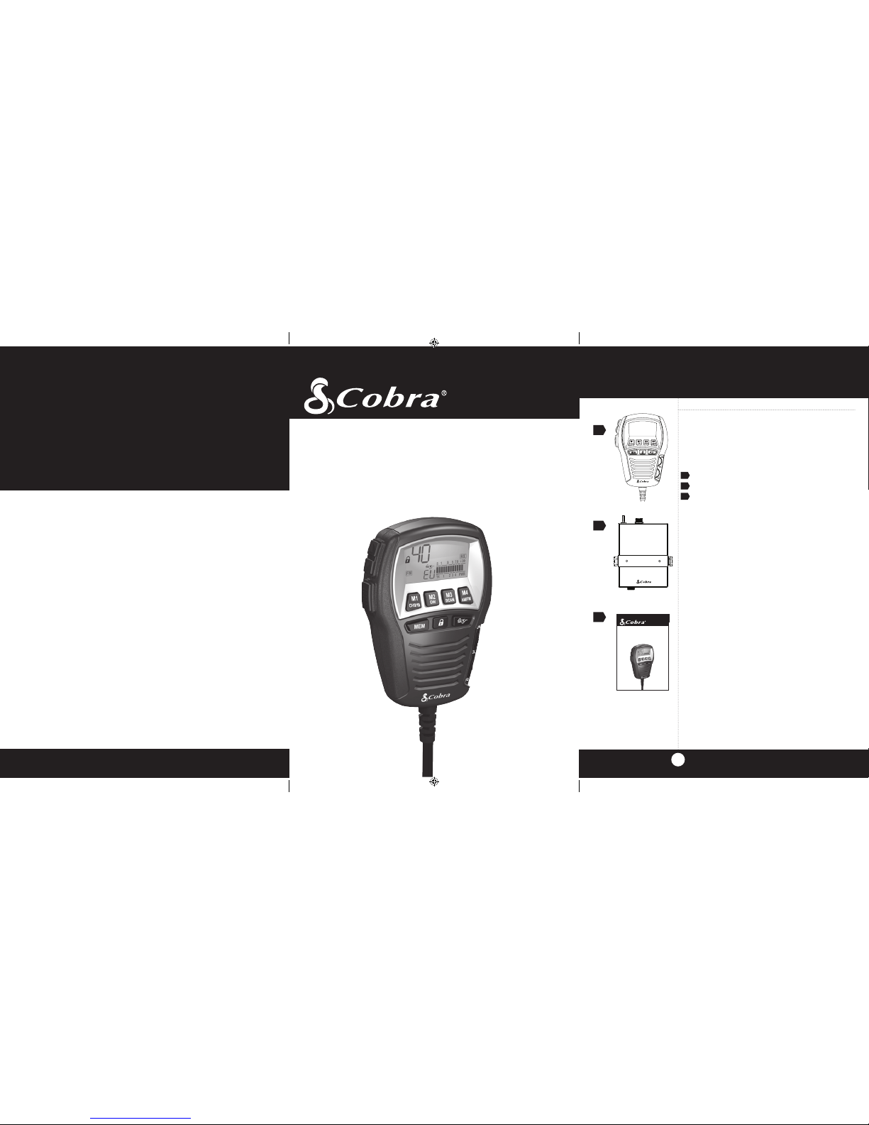
What’s Included with Your 75 ST EU
1. 75 ST EU Microphone Controller
2. CB Transceiver and Mounting Hardware
3. Operating Manual
A1
75 ST EU
Multi-Standard Remote Mount
CB Radio with SoundTracker® System
Operating Instructions
for your Cobra
®
75 ST EU
3
1
2
©2012 Cobra Electronics Corporation
Printed in China
Part No. 480-819-P
Version C
Nothing Comes Close to a Cobra
®
75 ST EU
Multi-Standard Remote Mount
CB Radio with SoundTracker
®
System
Operating Instructions
for your Cobra
®
76 ST EU
©2012 Cobra Electronics Corporation
Printed in China
Part No. 480-819-P
NothingComes Close to a Cobra™
The Cobra line of quality products includes:
CB Radios
microTALK
®
Radios
Radar/Laser Detectors
Safety Alert® Traffic Warning Systems
Truck-Specific Navigation Systems
HighGear® Accessories
CobraMarine VHF Radios
Power Inverters
LED Lights
Jumpstarters
Accessories
For more information or to
order any of our products,
please visit our website:
www.cobra.com
75STEU_MANL_ENG.indd 1-3 12/28/12 2:29 PM
Page 2
34
NOTES
Our Thanks to You and
Customer Assistance
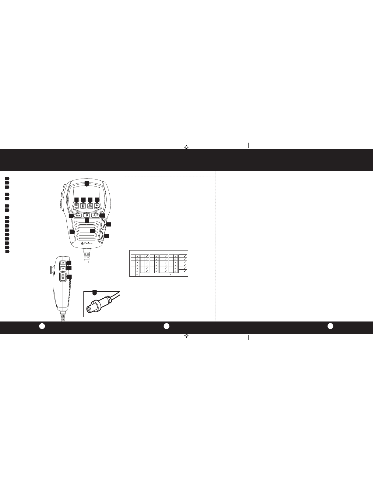
Controls and Indicators
1 SoundTracker® Key
2 Memory Key
3 Channel 9/19/Memory
Location 1 Key
4 LCD Display Panel
5 Dual Watch/Memory Location
2 Key
6 Scan/Memory Location 3 Key
7 AM/FM/Memory Location
4 Key
8 On/Off/Volume Control
9 Lock Key
10 Squelch Control
11 Microphone
12 Speaker
13 Channel Up Button
14 Channel Down Button
15 PTT (Push-To-Talk) Key
16 Quick Disconnect/Connector
A2 A3
3
8
9
1
4
16
13
12
2
Thank you for purchasing the Cobra 75 ST EU CB Radio Transceiver/
Microphone Controller. Properly used, this Cobra product will give you many
years of reliable service.
NOTICE!
Before using this transceiver, please check that the radio has been
programmed on the frequency band specifications and operating modes
allowed by the regulations valid in the country where the product is used.
If not, please proceed to modify the frequency band programming, as
described in this owner’s manual page 11. This transceiver is programmed
at the factory on the EU1 frequency band (40 CH AM 4W/40 CH FM 4W).
Customer Assistance
Should you encounter any problems with this
product, or not understand its many features, please refer to this owner’s
manual. If you require further assistance after reading this manual, please
contact your local dealer.
This equipment is intended for use in:
For Warranty, Product Service and Accessory Information
Please contact your local dealer or distributor.
See the enclosed leaflet, which provides contact information for the Cobra
international distributors.
AT
BA
BE
BG
CH
CZ
DE
This equipment is intended for use in:
Countries of use
EE
ES
FI
FR
GB
GR
HR
HU
IE
IS
IT
NL
NO
PT
RO
RS
SE
SI
SK
TR
LT
LV
LU
DK
MK
MT
CY
UA
RU
PL
5 6 7
10
14
15
11
75STEU_MANL_ENG.indd 1-3 12/28/12 2:29 PM
Page 3

Table of Contents
Contents
Features ........................................................................................... 1
The CB Story ................................................................................. A1
Included Accessories
Controls & Indicators ...................................................................A2
Our Thanks to You .......................................................................A3
Customer Assistance
Installation
Transceiver Location ................................................................... 2
Mounting Transceiver .................................................................. 3
Mounting and Connections .......................................................... 4
75 ST EU Fuses .......................................................................... 6
Microphone Hanger ..................................................................... 7
Antenna........................................................................................ 8
External Speaker ......................................................................... 9
Noise Interference ....................................................................... 9
Operating Your 75 ST EU
Turning On Your CB .................................................................. 10
Selecting a Channel (Country of Use) ....................................... 11
Activating SoundTracker® ........................................................... 12
Testing SoundTracker® .............................................................. 13
Setting the Squelch.................................................................... 14
LCD Display ............................................................................... 16
Receive/Transmit ....................................................................... 17
Emergency Channel 9 ............................................................... 18
One-Touch Channel 19 ............................................................. 19
Key Lock .................................................................................... 20
Frequency Display ..................................................................... 21
All Channel Scan ....................................................................... 22
Channel Saver Feature.............................................................. 23
Retrieving Channels From Memory ........................................... 24
Dual Watch ................................................................................ 25
Home & Office Set-Up ............................................................... 27
Frequency Ranges ....................................................................... 28
75 ST EU Specifications .............................................................. 31
Optional Accessories ................................................................... 32
Features of This Product
• AM/FM1W/4WMulti-Country
Programmable Remote Mount
Transceiver
• SoundTracker
• RemoteMount
Installation System
• FullFeaturedIlluminated
LCD Display Panel
• DualWatchChannelMonitor
• FullChannelScan
• FourMemoryLocations
• One-TouchInformation
Channel 19
• One-TouchEmergency
Channel 9
• KeyLock
• 10FootFlexibleCord
• QuickDisconnect
• SquelchControl
®
System
Declaration of Conformity ........................................................... 33
1
Page 4
3
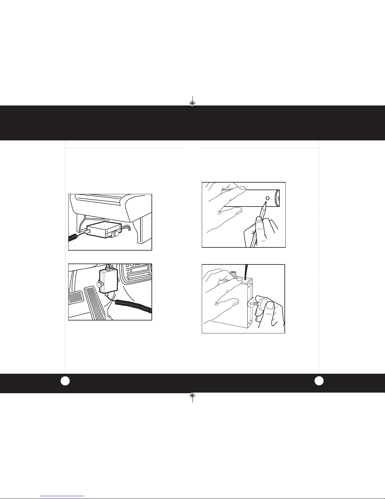
Installation
Mounting the Transceiver
1 Hold Cobra 75 ST EU transceiver bracket in exact location
desired for mounting.
2 Using it as a template, mark the location for the mounting
screws (included.)
3 Mount the Transceiver as shown.
Mounting the
Transceiver
Note
Make certain that nothing will
interfere with the installation of
mounting screws, before drilling
holes.
Installation
Location
Mount your Cobra 75 ST EU Transceiver in a convenient location,
away from moisture and direct sunlight, in a location that will not
interfere with driving.
Cobra suggests mounting it either under the front seat or on the
fire wall.
Under the Front Seat Installation
On the Fire Wall Installation
Location
2
Under the
Front Seat
Installation
Note
Do not mount under the hood,
near heat ducts or in direct line of
the car’s heater.
75STEU_MANL_ENG.indd 2-3 12/28/12 2:30 PM
Page 5
5
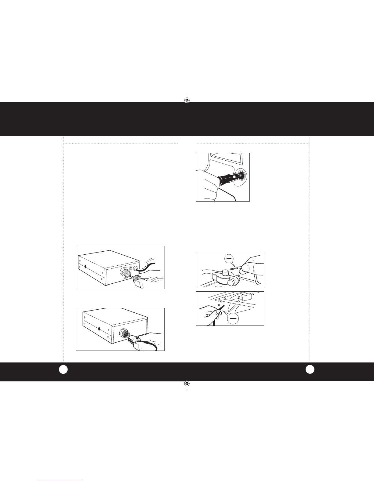
Installation
1 Connect to 12V Dashborad Connection.
2 For constant 12 volt source power, remove the cigarette lighter
plug and connect the red wire marked “BATT(+)” directly to the
positive side of the battery or to a connection on the fuse block
that is always on.
3 Connect the black wire “Ground” to the negative side of the
car, usually the chassis. Any other location with good electrical
contact (paint removed) will also work.
Mounting and
Connections
Caution
Leavingthe75STEUonafter
your car is turned off can drain
your car battery when connected to
a constant 12 volt source. When
connected to an accessory 12 volt
source the unit will turn off when
vehicle is turned off.
Installation
Mounting and Connections
The Transceiver is held by two screws, permitting mounting in the
manner most convenient for your installation.
Mounting hardware is supplied for mounting the Transceiver. The
mounting must be mechanically strong and also provide a good
electrical connection to the chassis of the vehicle. Proceed as
follows to mount junction box:
1 After you have determined the most convenient location in your
vehicle, hold the Cobra 75 ST EU Transceiver in the exact
location desired. If nothing will interfere with mounting it in the
desired position, use the Transceiver as a template to mark
the location for the mounting screws. Before drilling the holes,
make sure nothing will interfere with the installation of the
mounting screws.
2 Connect the antenna cable connector to the antenna
receptacle on the unit. Most CB antennas are terminated with
a type PL-259 plug and mate with the receptacle.
3 Connect the control unit to the front connector.
Mounting and
Connections
4
75STEU_MANL_ENG.indd 4-5 12/28/12 2:30 PM
Page 6
7
Installation
Installing Microphone Hanger
1 Hold microphone hanger in location desired for mounting.
Make certain that nothing will interfere with the hanger’s
installation.
2 Mark the location for the two mounting screws
(screws included).
3 Drill and mount microphone hanger.
Installing
Microphone
Hanger
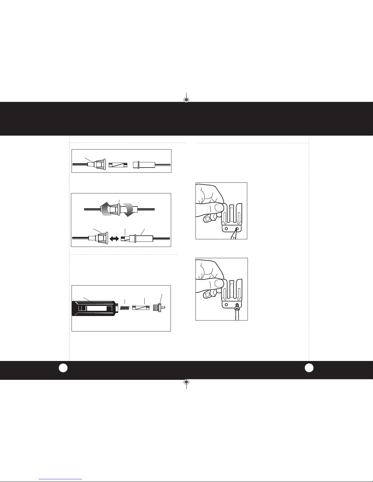
75 ST EU Fuses
6
Replacing the
In-Line Fuse
To replace the in-line fuse; push the ends of the holder
together then turn counter-clockwise and pull the two
sections apart.
Note
The radio is protected with a 2 fuse
system in the event that the user
decides not to use the cigarette
lighter plug.
Caution
For continued protection against fire
hazard, replace with same type 2A,
250V fuses.
2A, 250V FUSE
IN-LINE
FUSE HOLDER
FUSE
IN-LINE
FUSE HOLDER
IN-LINE
FUSE HOLDER
IN-LINE
FUSE HOLDER
Replacing the Fuse
Note
There is a retaining spring in
the CLP used for tension connectivity.
To replace the fuse in the cigarette light plug (CLP), rotate the
metal tip of the CLP to access the fuse.
Be sure not to lose the retaining spring within
the holder.
CIGARETTE
LIGHTER PLUG
RETAINING
SPRING
2A, 250V FUSE
METAL TIP
75STEU_MANL_ENG.indd 6-7 12/28/12 2:30 PM
Page 7

Installation
CB Antenna
For the most reliable operation and
maximum range, Cobra recommends using
a vertically polarized, quarter wave length
whip antenna (illustration A).
Shorter, loaded-type whips are adequate
when maximum range is not required
(illustration B).
CB Antenna
Installation
Note
Mobile installations (cars, trucks,
boats, etc) should be made only
with a non-directional antenna
system.
A standard antenna connector
(Type SO-239) is provided on the
ConnectorBoxforeasyconnection
to a standard PL-259 cable
termination.
Cobra antenna models are
recommended; see your local CB
dealer or order directly from Cobra
(see page 32).
Formaximumefficiencyinboat
installations, a ground plate is
required, unless the vessel has
a steel hull. Consult your CB
dealer for information regarding an
adequate grounding system.
8
9
Installation
External Speaker Installation
1 Mount external speaker in desired location.
2 Plug jack into the back of the Transceiver labeled EXT.
*The external speaker should have 4-8 ohms impedance and
be able to handle at least 4 watts.
External
Speaker
Installation
Note
Internal speaker is muted when
externalspeakerisconnected.
Ignition Noise
Interference
A
B
Ignition Noise Interference
The alternator and ignition system in your vehicle may limit your
ability to receive low signal levels. Other noise interference can
be the result of several different installation variables. Consult
your Cobra dealer or a 2-way radio technician to help locate and
correct the source of severe noise interference.
75STEU_MANL_ENG.indd 8-9 12/28/12 2:30 PM
Page 8

Installation
Installation
Installation
Installation
11
NOTICE!
Before using this transceiver, please check that the radio has been programmed on the
frequency band specifications and operating modes allowed by the regulations valid in the
country where the product is used. If not, please proceed to modify the frequency band
programming, as described below. This transceiver is programmed at the factory on the
EU1 frequency band (40 CH AM 4W/40 CH FM 4W).
Operation
10
11
Operation
Turning On
1 Rotate the power On/Off/Volume
Control clockwise.
2 Turn the Squelch Control
counterclockwise until
noise is heard.
3 Adjust volume to a
comfortable level.
Selecting a Channel
1 Change channels by pressing
either the channel p up button
or channel q down button .
2 To quick-advance channels,
press and hold either button.
Turning Your
CB On
Selecting a
Channel
Note
Sound clarity is measured by the
ratio of the signal level to the noise
level. The higher the signal-tonoise ratio, the better the sound.
To Program Radio to Country of Usage
1 Press and hold the ST (SoundTracker®) button.
2 Turn power on to the radio. Release the SoundTracker
®
button. The band ID will flash on default ID “EU” (first
use only).
3 Press and release the Channel UP button for you ID
selection.
4 ID sequence: EU1aEUaCEa Gb aPLa E1 aI2a DEa
dE1a EU.
5 Press and release the SoundTracker
®
button again to set and
exit. The 75 ST EU will remember this setting after power
is turned off.
CB Antenna
Only a properly matched Antenna system will allow maximum
power output. In mobile installations (cars, trucks, boats, etc.), an
Antenna system that is non-directional should be used. When
installed in a boat, the transceiver will not operate at maximum
efficiency without a ground plate unless the vessel has a steel hull.
Before installing the transceiver in a boat, consult your dealer for
information regarding an adequate grounding system.
75STEU_MANL_ENG.indd 10-11 12/28/12 2:30 PM
Page 9

Installation
Installation
12
Installation
Installation
13
Operation
12
13
Operation
Activating SoundTracker®
1 Press and release the SoundTracker key.
2 will be displayed on the LCD readout..
Activating
SoundTracker
®
Testing SoundTracker®
1 Select any unused channel on
your CB.
2 Open the squelch control
fully by turning the knob
counterclock-wise until it stops.
3 Turn the volume up louder than
your normal listening level.
4 Press and release the
SoundTracker key. Notice the
significant reduction in noise.
S 1 3 5 7 9 +30
TX 1 2 3 4 PWR
RX
AM
ST
Testing
SoundTracker
®
Note
If noise level does not decrease,
check antenna system and
electronic vehicle interference.
S 1 3 5
7 9 +30
TX 1 2 3
4 PWR
RX
AM
ST
S 1 3 5 7 9 +30
RX
ST
75STEU_MANL_ENG.indd 12-13 12/28/12 2:30 PM
Page 10

Operation
Setting Squelch
1 Turn CB on by turning the volume control clockwise. Adjust
the volume to a comfortable level.
2 Before setting the squelch control on your radio, you must
select a channel that is not in use.
3 Turn on SoundTracker
®
.
4 To achieve the Desired Squelch Setting (DSS): Think of
your Squelch Control as a gate for incoming signals. If you
turn the Squelch Control fully clockwise, it raises the “squelch
gate” so high that no signals get through.
Setting the
Squelch
14
15
Operation
Setting Squelch
5 If you turn the squelch control fully counter-clockwise, it
lowers the “squelch gate” so low that everything gets through
- noise, weak signals and strong signals.
6 To set the “squelch gate” to the DSS-Desired Squelch
Setting, turn the squelch control counterclockwise until you
hear noise. Then turn the squelch control back clockwise just
until the noise stops. Now only strong signals get through.
The Desired Squelch Setting, (DSS) only allows actual
transmissions to come through. This effectively blocks out
unwanted noise.
NOISE
WEAK SIGNALS
MEDIUM SIGNALS
STRONG SIGNALS
GATE CLOSED
GATE
OPEN
NOISE
WEAK SIGNALS
MEDIUM SIGNALS
STRONG SIGNALS
Gate open
Gate closed
Setting the
Squelch
75STEU_MANL_ENG.indd 14-15 12/28/12 2:30 PM
Page 11

17
Operation
To Transmit
In CB Mode:
1 Press the PTT (Press-To-Talk)
button.
2 The
TX
icon will appear.
3 Hold the microphone about 2
inches from your mouth and
speak in a normal voice.
4 Release the PTT button and
you will automatically be in
the receive mode again.
To Transmit
Caution!
Be sure the antenna
is properly connected
to the radio before transmitting.
Prolonged transmitting without
an antenna, or a poorly matched
antenna, could cause damage to
the transmitter.
Note
Be sure the radio is programmed
to the band that is allowed in the
country of use.
Operation
LCD Display
Your Cobra 75 ST EU CB is designed with a liquid crystal display
(LCD) that indicates channel number, frequency and operating mode.
2 digit channel display / 5 digit frequency display
AM
= Amplitude Modulation Indicator
FM
= Frequency Modulation Indicator
EU
= Band In Use
M
= Memory Indicator/Number
SCAN
= Scan Indicator
DW
= Dual Watch Indicator
= Lock Indicator
= Emergency Channel 9 Indicator
= SoundTracker
®
Indicator
RX
= Receive Indicator
TX
= Transmit Indicator
Signal Strength Meter
LCD Display
Note
To avoid damaging the LCD
display, do not subject your CB
radiotoextremetemperatures
(below -5°F or above 140°F) for
extendedperiodsoftime.
16
S 1 3 5 7 9 +30
TX 1 2 3 4 PWR
TX
RX
DW
AM
M
FM
SCAN
ST
PRESS &
HOLD
S 1 3 5 7 9 +30
TX 1 2 3 4 PWR
TX
FM
RELEASE
To Receive
1 Your 75 ST EU is
automatically in the receive
mode and
RX
(Receive
Indicator) is illuminated.
To Receive
S 1 3 5 7 9 +30
TX 1 2 3 4 PWR
RX
FM
TX
RX
DW
S 1 3 5 7 9 +30
TX
RX
ST
S 1 3 5 7 9 +30
RX
ST
75STEU_MANL_ENG.indd 16-17 12/28/12 2:30 PM
Page 12

19
Operation
One Touch
Channel 9
and 19
Operation
Emergency
Channel 9 or
Information
Channel 19
18
1 To access emergency channel 9, press Channel 9/19 key
once.
2 You are now on emergency channel 9 and the icon
will appear.
3 To access information channel 19, press Channel 9/19
key again.
PUSH
ONCE
S 1 3 5 7 9 +30
TX 1 2 3 4 PWR
RX
FM
PUSH
AGAIN
4 You are now on information channel 19.
5 Press 9/19 again to return to the original channel
selected.
6 Original channel.
THIRD
TIME
S 1 3 5 7 9 +30
TX 1 2 3 4 PWR
RX
FM
S 1 3 5 7 9 +30
TX 1 2 3 4 PWR
RX
FM
S 1 3 5 7 9 +30
RX
75STEU_MANL_ENG.indd 18-19 12/28/12 2:30 PM
Page 13

21
Operation
5 Digit
Frequency
Display
Operation
Key Lock
20
1 Press Key Lock button to prevent unintentional channel
changing.
2 You are now locked and the icon will appear.
3 Press Key Lock again to deactivate.
PRESS &
RELEASE
S 1 3 5 7 9 +30
TX 1 2 3 4 PWR
RX
FM
4 Push and hold Memory Key for 5 seconds.
5 Display will change to the 5 digit frequency of the
channel selected.
6 Push and hold Memory key again for approximately
5 seconds.
7 Display will change back to channel display.
PRESS &
HOLD
S 1 3 5 7 9 +30
TX 1 2 3 4 PWR
RX
FM
PRESS &
RELEASE
S 1 3 5 7 9 +30
TX 1 2 3 4 PWR
RX
FM
TX
RX
DW
PRESS &
HOLD
75STEU_MANL_ENG.indd 20-21 12/28/12 2:30 PM
Page 14

23
Operation
Channel Saver
Feature
Operation
All Channel
Scan
Note
The75STEUwillstopscanning
and monitor a channel when it
receives an incoming transmission.
Five seconds after the
transmissionstops,the75STEU
resumes the scanning function.
22
1 Set Squelch Control (SQL) to desired setting DSS. See
page 14 to set DSS.
2 Press Scan key. Unit will start scanning.
3 When activity is found on a channel, scanning will stop.
Scan icon will appear
4 Press any key to stop scanning sequence.
Channel Saver Feature
Automatically retains the last channel used when CB is
turned off and returns you to that channel when CB is turned
back on. This feature works only when connected to a
constant 12 volt source.
Saving Channels in Memory
1 Select desired channel to store in memory.
2 PRESS and RELEASE the Memory key.
3 PRESS and HOLD the desired Memory Location key to
lock channel into memory.
4 The Memory location will appear on the display.
PRESS
ANY KEY
PRESS &
RELEASE
PRESS &
HOLD
S 1 3 5 7 9 +30
TX 1 2 3 4
PWR
RX
FM
M
S 1 3 5 7 9 +30
RX
75STEU_MANL_ENG.indd 22-23 12/28/12 2:30 PM
Page 15

Operation
24
25
Dual Watch
Dual Watch
Dual Watch allows you to simultaneously monitor any two
preselected channels at one time.
1 Adjust squelch (SQL) setting to the DSS level
(see page 14).
2 Set CB to one of the channels you wish to monitor.
3 PRESS and Hold the DW button until a beep is heard.
Dual Watch
Retrieving
Channels from
Memory
1 PRESS and RELEASE the Memory key.
2 PRESS and RELEASE the desired Memory Location key.
3 The channel in the memory location will be recalled.
4 Repeat to recall other Memory Locations.
S 1 3 5 7 9 +30
TX 1 2 3 4 PWR
RX
M
FM
PRESS &
RELEASE
S 1 3 5 7 9 +30
TX 1 2 3 4 PWR
RX
DW
FM
PRESS &
HOLD
75STEU_MANL_ENG.indd 24-25 12/28/12 2:30 PM
Page 16

Dual Watch
4 Select new channel.
5 Press and hold DW button until a beep is heard.
6 The
DW
icon appears and monitoring begins.
7 Press any key to stop monitoring function.
Note
The75STEUwillalternate
between both channels
until it receives an incoming
transmission. Five seconds after
the transmission stops, it will again
alternate between both channels.
26
27
Home and Office Set-Up
PRESS &
HOLD
S 1 3 5 7 9+30
TX 1 2 3 4 PWR
RX
FM
M
Dual Watch
S 1 3 5 7 9 +30
TX 1 2 3 4 PWR
RX
DW
FM
PRESS
ANY KEY
Base Station Operation
(From 230V AC House
Current)
Warning!
Do not attempt to operate this
transceiver by connecting it directly to
230V AC.
Base Station Operation
(From 230V AC House Current)
To operate your transceiver from home or office you will need
a 13.2 volt DC Power Pack rated at a minimum of 2 amps, and
a properly installed base station antenna.
Simply connect the red (+) and black (-) leads of the
transceiver to the corresponding terminals of the power pack.
+—
75STEU_MANL_ENG.indd 26-27 12/28/12 2:30 PM
Page 17

Frequency Ranges
28
29
Frequency Ranges
Band Channels Power Country (MHz)
EU 40 CH AM 1W Europe/France CEPT Frequencies
EU 40 CH FM 4W Europe/France CEPT Frequencies
EU1* 40 CH AM 4W *Europe 26.965-27.405
40 CH FM 4W *Europe
CE 40 CH FM only 4W CEPT Frequencies
Gb (UK) 40 CH FM 4W England (UK) UK Frequencies
Gb (UK) 40 CH FM 4W England (UK) CEPT Frequencies
PL 40 CH AM 4W Poland Polish Frequencies
PL 40 CH FM 4W Poland Polish Frequencies
E1 40 CH AM 4W Italy/Spain CEPT Frequencies
E1 40 CH FM 4W Italy/Spain CEPT Frequencies
I2 36 CH AM 4W Italy Italian Frequencies
I2 36 CH FM 4W Italy Italian Frequencies
DE 40 CH AM 1W Germany 26.965 (CH1) to
27.405(CH40)
CEPT Frequencies
DE 80 CH FM 4W Germany 1st 40 CH
dE1 40 CH AM 4W CEPT Frequencies
80 CH FM 4W 2nd 40 CH
NOTE: If the country of usage is not listed above, please consult with your local
communications authority for frequency usage.
*Not all countries allow EU1. Please consult with your local authority before use.
Ch. No. Freq.(MHz)
1 26.965
2 26.975
3 26.985
4 27.005
5 27.015
6 27.025
7 27.035
8 27.055
9 27.065
10 27.075
11 27.085
12 27.105
13 27.115
14 27.125
15 27.135
16 27.155
17 27.165
18 27.175
19 27.185
20 27.205
21 27.215
22 27.225
23 27.255
24 27.235
25 27.245
26 27.265
27 27.275
28 27.285
29 27.295
30 27.305
31 27.315
32 27.325
33 27.335
34 27.345
35 27.355
36 27.365
37 27.375
38 27.385
39 27.395
40 27.405
Ch. No. Freq.(MHz)
1 27.60125
2 27.61125
3 27.62125
4 27.63125
5 27.64125
6 27.65125
7 27.66125
8 27.67125
9 27.68125
10 27.69125
11 27.70125
12 27.71125
13 27.72125
14 27.73125
15 27.74125
16 27.75125
17 27.76125
18 27.77125
19 27.78125
20 27.79125
21 27.80125
22 27.81125
23 27.82125
24 27.83125
25 27.84125
26 27.85125
27 27.86125
28 27.87125
29 27.88125
30 27.89125
31 27.90125
32 27.91125
33 27.92125
34 27.93125
35 27.94125
36 27.95125
37 27.96125
38 27.97125
39 27.98125
40 27.99125
Ch. No. Freq.(MHz)
1 26.960
2 26.970
3 26.980
4 27.000
5 27.010
6 27.020
7 27.030
8 27.050
9 27.060
10 27.070
11 27.080
12 27.100
13 27.110
14 27.120
15 27.130
16 27.150
17 27.160
18 27.170
19 27.180
20 27.200
21 27.210
22 27.220
23 27.250
24 27.230
25 27.240
26 27.260
27 27.270
28 27.280
29 27.290
30 27.300
31 27.310
32 27.320
33 27.330
34 27.340
35 27.350
36 27.360
37 27.370
38 27.380
39 27.390
40 27.400
Band ID EU:
EU EU1*
AM 1.0W AM 4.0W
FM 4.0W FM 4.0W
Band ID CE:
CEPT
FM 4.0W
Band ID Gb (UK):
United Kingdom
40 CH FM 4.0W
Band ID PL:
Poland
AM 4.0W
FM 4.0W
Ch. No. Freq.(MHz)
1 26.965
2 26.975
3 26.985
4 27.005
5 27.015
6 27.025
7 27.035
8 27.055
9 27.065
10 27.075
11 27.085
12 27.105
13 27.115
14 27.125
15 27.135
16 27.155
17 27.165
18 27.175
19 27.185
20 27.205
21 27.215
22 27.225
23 27.255
24 27.235
25 27.245
26 27.265
27 27.275
28 27.285
29 27.295
30 27.305
31 27.315
32 27.325
33 27.335
34 27.345
35 27.355
36 27.365
37 27.375
38 27.385
39 27.395
40 27.405
Band ID E1:
Spain
AM 4.0W
FM 4.0W
*Not all countries allow EU1. Please consult with your local authority before use.
75STEU_MANL_ENG.indd 28-29 12/28/12 2:30 PM
Page 18

Frequency Ranges continued
30
31
75 ST EU Specifications
Ch. No. Freq.(MHz)
1 26.965
2 26.975
3 26.985
4 27.005
5 27.015
6 27.025
7 27.035
8 27.055
9 27.065
10 27.075
11 27.085
12 27.105
13 27.115
14 27.125
15 27.135
16 27.155
17 27.165
18 27.175
19 27.185
20 27.205
21 27.215
22 27.225
23 27.255
24 27.235
25 27.245
26 27.265
27 27.275
28 27.285
29 27.295
30 27.305
31 27.315
32 27.325
33 27.335
34 27.345
35 27.355
36 27.365
37 27.375
38 27.385
39 27.395
40 27.405
GENERAL
Modulation Mode ...................................... FM/AM
Frequency Range ..................................... 26.565 to 27.99125 MHZ
Frequency Tolerance ...............................0.005 %
Frequency Control ................................... PLL (Phase Lock Loop) Synthesizer
Operating Temperature Range ................-20° C TO + 55° C
Microphone ............................................... Internal
Input Voltage ...........................................13.2 VDC nom. (negative ground)
Current Drain ............................................ Transmit: AM/FM full mod., 1.4A (maximum)
Receive: Squelched, 0.9 A;
Full audio output, 1.2A (nominal)
Maximum Duty Cycle ..............................2 minute transmit (TX), 5 minute stand-by (RX)
Size ........................................................8.625”D x 7.28125”W x 2.8125”H
Weight ......................................................2 lbs.
Antenna Connector ..................................UHF; SO-239
Meter .........................................................LCDs; indicates relative power output
and received signal strength
TRANSMITTER
Power Output ...........................................4 watts FM, 4/1 watt AM
Modulation ................................................ AM (Amplitude Modulation)
FM (Frequency Modulation)
Frequency Response ...............................300 to 3000 Hz
Output Impedance ....................................50 ohms, unbalanced
RECEIVER
Sensitivity .................................................Less than 1 µV for 10 dB (S+N) /N
Selectivity .................................................6 dB @ 7 KHz, 60 dB @ 10KHz
Image Rejection .......................................80 dB, typical
Adjacent-Channel Rejection .....................60 dB, typical
IF Frequencies .........................................Double Conversion: 1st: 10.695 MHz
2nd: 455 KHz
Automatic Gain Control (AGC) ................. Less than 10 dB change in audio
output for inputs from 10 to 50,000 microvolts
Automatic Noise Limiter ...........................RF type
Squelch .....................................................Adjustable; threshold less than 1µV
Audio Output Power .................................2 Watts
Frequency Response ...............................300 to 3000 Hz
Distortion ..................................................Less than 7% @3 watts @ 1000 Hz
Built-in Speaker ........................................8 ohms, 2 Watts
External Speaker (Not supplied) ..................8 ohms; disables internal speaker
when connected
(SPECIFICATIONS SUBJECT TO CHANGE WITHOUT NOTICE)
Ch. No. Freq.(MHz)
1 26.965
2 26.975
3 26.985
4 27.005
5 27.015
6 27.025
7 27.035
8 27.055
9 27.065
10 27.075
11 27.085
12 27.105
13 27.115
14 27.125
15 27.135
16 27.155
17 27.165
18 27.175
19 27.185
20 27.205
21 27.215
22 27.225
23 27.255
24 27.245
25 27.265
26 26.875
27 26.885
28 26.895
29 26.905
30 26.915
31 26.925
32 26.935
33 26.945
34 26.955
35 26.855
36 26.865
Ch. No. Freq.(MHz)
1 26.965
2 26.975
3 26.985
4 27.005
5 27.015
6 27.025
7 27.035
8 27.055
9 27.065
10 27.075
11 27.085
12 27.105
13 27.115
14 27.125
15 27.135
16 27.155
17 27.165
18 27.175
19 27.185
20 27.205
21 27.215
22 27.225
23 27.255
24 27.235
25 27.245
26 27.265
27 27.275
28 27.285
29 27.295
30 27.305
31 27.315
32 27.325
33 27.335
34 27.345
35 27.355
36 27.365
37 27.375
38 27.385
39 27.395
40 27.405
Ch. No. Freq.(MHz)
41 26.565
42 26.575
43 26.585
44 26.595
45 26.605
46 26.615
47 26.625
48 26.635
49 26.645
50 26.655
51 26.665
52 26.675
53 26.685
54 26.695
55 26.705
56 26.715
57 26.725
58 26.735
59 26.745
60 26.755
61 26.765
62 26.775
63 26.785
64 26.795
65 26.805
66 26.815
67 26.825
68 26.835
69 26.845
70 26.855
71 26.865
72 26.875
73 26.885
74 26.895
75 26.905
76 26.915
77 26.925
78 26.935
79 26.945
80 26.955
Band ID I2:
Italy 2
AM 4.0W
FM 4.0W
Band ID DE:
Germany
40 CH AM 1.0W
80 CH FM 4.0W
Trademark Acknowledgement
Cobra®, Nothing Comes Close to a Cobra® and the snake design are registered trademarks of Cobra
Electronics Corporation, USA. Cobra Electronics Corporation™ is a trademark of Cobra Electronics
Corporation, USA.
Band ID I1:
Italy 1
AM 4.0W
FM 4.0W
Ch. No. Freq.(MHz)
1 26.965
2 26.975
3 26.985
4 27.005
5 27.015
6 27.025
7 27.035
8 27.055
9 27.065
10 27.075
11 27.085
12 27.105
13 27.115
14 27.125
15 27.135
16 27.155
17 27.165
18 27.175
19 27.185
20 27.205
21 27.215
22 27.225
23 27.255
24 27.235
25 27.245
26 27.265
27 27.275
28 27.285
29 27.295
30 27.305
31 27.315
32 27.325
33 27.335
34 27.345
35 27.355
36 27.365
37 27.375
38 27.385
39 27.395
40 27.405
Band ID EU:
France
AM 1.0W
FM 4.0W
Band ID dE1:
Germany
40 CH AM 4.0W
80 CH FM 4.0W
75STEU_MANL_ENG.indd 30-31 12/28/12 2:30 PM
Page 19

Optional Accessories
32
33
Replacement Microphone
Bracket
21” Base Loaded Magnet Mount
Antenna
HG A1000
38” Base Loaded Magnet Mount
Antenna
HG A1500
Dynamic External
Speaker
HG S100
Noise Cancelling With
Talk Back External
Speaker
HG S500
Noise Cancelling
External Speaker
HG S300
You can find quality Cobra products and accessories at your local Cobra dealer.
Declaration of Conformity
Declaration of Conformity
We, Cobra Electronics Europe Limited of
Dungar House
Northumberland Avenue
Dun Laoghaire
County Dublin, Ireland
Declare under our sole responsibility that the product:
75 ST EU
CB radio
to which this declaration relates, is in conformity with the following standards and/ or other normative
documents when properly installed and maintained and used for their intended purpose:
EN60950-1:2006 / A12:2011
EN62311 (2008)
EN 301 489-1 V1.9.2 (2011-09)
EN 301 489-13 V1.2.1 (2002-08)
EN 300 433-2 V1.3.1 (2011-07)
EN 300 433-1 V1.3.1 (2011-07)
We hereby declare that the above named product is in conformity to all the essential requirements of the
Directive 1999/5/EC.
The conformity assessment procedure referred to in Article 10 and detailed in Annex III or IV of Directive
1999/5/EC has been followed with the involvement of the following Notified Body:
BABT, Forsyth House, Churchfield Road, Walton-on-Thames, Surrey, KT12 2TD, UK
Identification mark 0168 (Notified Body Number)
The equipment will also carry the Class 2 equipment identifier:
The technical documentation relevant to the above equipment will be held at:
Cobra Electronics Europe Limited of
Dungar House
Northumberland Avenue
Dun Laoghaire
County Dublin, Ireland
JEAN-LOUIS POOT, Managing Director March 2013
75STEU_MANL_ENG.indd 32-33 12/28/12 2:30 PM
 Loading...