

Cobra 200GTL DX Owner's Manual
A1
Owner’s Manual
AMATEUR 10 METER MOBILE RADIO
200 GTL DX
Printed in Philippines
Part No. 480-217-P
Version A
®
English
A1
English
Our Thanks to You and
FCC License Required
©2005 Cobra®Electronics Corporation
6500 West Cortland Street
Chicago, Illinois 60707 USA
www.cobra.com
Introduction
Our Thanks to You
•
Thank you for purchasing a Cobra amateur mobile radio. Properly used,
this Cobra product will give you many years of reliable service.
FCC License Required
•
The United States Federal Communications Commission (FCC)
requires that users of the frequencies on which this radio
operates be licensed. See page 16 for licensing and other
FCC information.
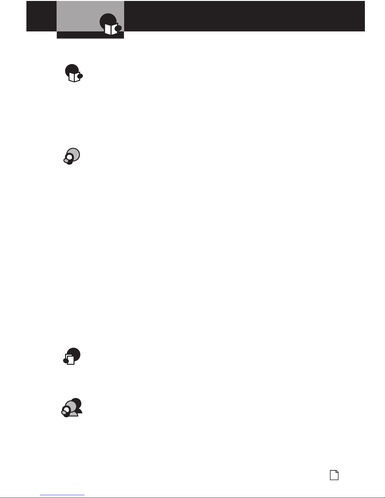
Press-To-Talk
Button (PTT)
WARNING
RISK OF ELECTRIC SHOCK.
DO NOT OPEN. DO NOT REMOVE
COVER OR BACK. NO USER
SERVICEABLE PARTS INSIDE.
REFER TO SERVICING TO
QUALIFIED SERVICE PERSONNEL.
A3
English
Microphone and Features
A2
English
Controls and Indicators
Introduction Introduction
Features
•
--
4341 Operating Frequencies
Allows operation on all
available frequencies.
--
430 Watts Output Power
Provides maximum
power on AM and FM
100 PEP SSB.
--
4Dual Finals
Provides steady output power.
--
4Dual Power
Allows operation on Low and
High power.
--
4All Mode Operation
•
Continuous wave
• Frequency or amplitude modulation
• Upper or lower sideband.
--
4SWR Calibration
Allows measurement and adjustment
of the antenna system.
--
4Antenna Warning Indicator
Illuminates when the antenna system
needs repair or adjustment.
--
4Echo Control
Allows control of echo effect.
--
4Frequency Display
Large 6 digit numeric and
Dual 7 Segment displays on
the front of the unit.
--
4Large Analog Meter
Provides high visibility of
status meter.
--
4NightWatch
™
Panel
Electroluminescent illumination of
front panel for night operation.
--
44 Pin Front Mic Connector
Allows convenient installation in-dash.
--
4Mic Gain Control
Allows increased voice clarity by
dynamically boosting microphone.
This Cobra radio has a superior receiver that includes an RF gain control and noise
blanker circuitry as well as an automatic noise limiter. The receiver also features
increased protection against cross modulation and strong adjacent signals.
To obtain maximum performance, please read carefully the descriptions and
operating instructions in this manual.
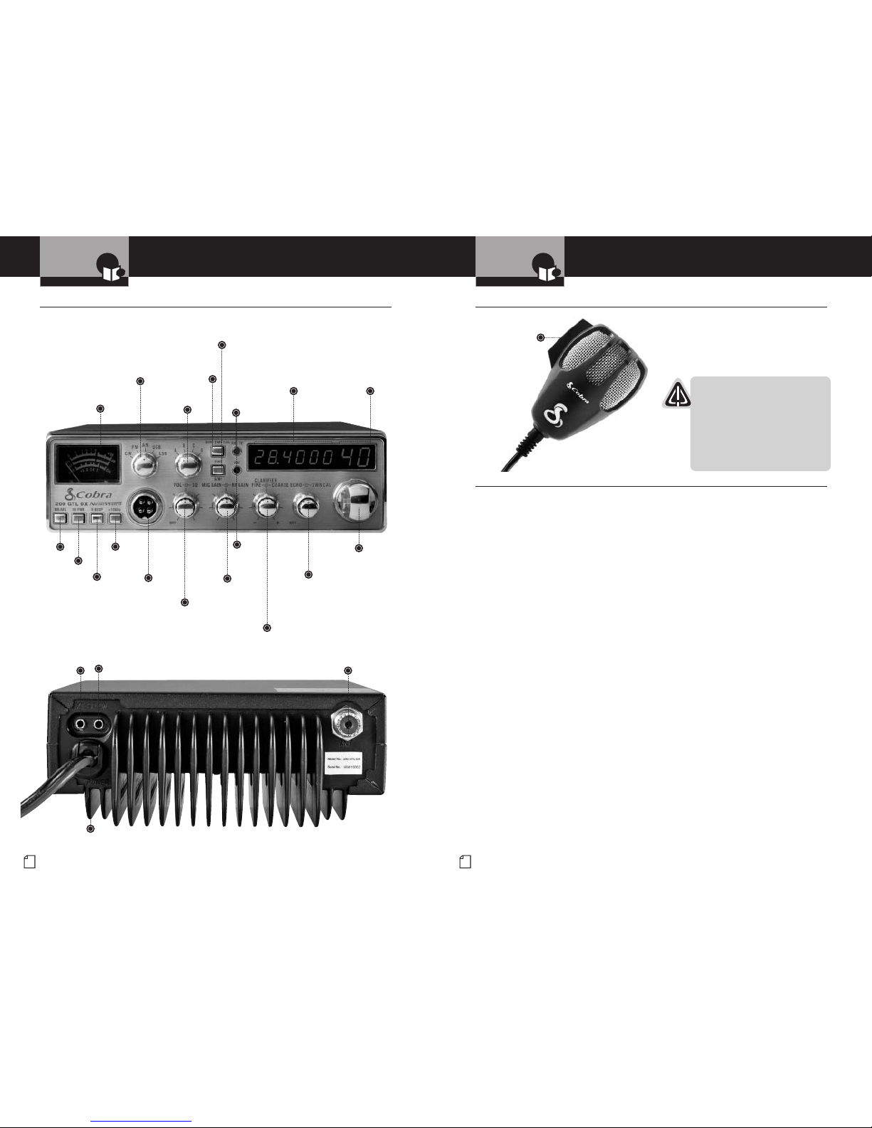
Controls and Indicators
•
Frequency
Selector
Echo
(center knob)
SWR CAL
(outer ring)
Analog
Meter
Antenna
Warning
Indicator
Band
A / B / C / D
CW / FM / AM /
USB / LSB
Dim /
SWR CAL
RX / TX
Indicator
SWR /
S/RF
Dual 7
Segment
Frequency
Display
Six Digit
Frequency
Display
Antenna
Connector
External
Speaker
Connector
Continuous
Wave Connector
Microphone
Connector
NB / ANL
High/Low Power
R Beep
+10
KHz
Microphone Gain
(center knob)
RF Gain
(outer ring)
Power Cord
Connector
Off / On / Volume
(center knob)
Squelch
(outer ring)
Clarifier
Fine (center knob)
Coarse (outer ring)
Microphone
•
1
Nothing comes close to a Cobra
®
Contents
Introduction
Introduction
Our Thanks to You . . . . . . . . . . . . . . . . . . . . . . . . . . . . . . . . . . . . . . . . . . . A1
FCC License Required . . . . . . . . . . . . . . . . . . . . . . . . . . . . . . . . . . . . . . . . . A1
Controls and Indicators . . . . . . . . . . . . . . . . . . . . . . . . . . . . . . . . . . . . . . . . A2
Microphone . . . . . . . . . . . . . . . . . . . . . . . . . . . . . . . . . . . . . . . . . . . . . . . . . A3
Features . . . . . . . . . . . . . . . . . . . . . . . . . . . . . . . . . . . . . . . . . . . . . . . . . . . A3
Your Mobile Radio
Specifications . . . . . . . . . . . . . . . . . . . . . . . . . . . . . . . . . . . . . . . . . . . . . . . . 2
Included in this Package . . . . . . . . . . . . . . . . . . . . . . . . . . . . . . . . . . . . . . . . 4
Installation and Connection . . . . . . . . . . . . . . . . . . . . . . . . . . . . . . . . . . . . . . 5
Operation . . . . . . . . . . . . . . . . . . . . . . . . . . . . . . . . . . . . . . . . . . . . . . . . . . . . 8
Controls . . . . . . . . . . . . . . . . . . . . . . . . . . . . . . . . . . . . . . . . . . . . . . . . . . . . . 9
Frequency . . . . . . . . . . . . . . . . . . . . . . . . . . . . . . . . . . . . . . . . . . . . . . . . . . 12
Indicators . . . . . . . . . . . . . . . . . . . . . . . . . . . . . . . . . . . . . . . . . . . . . . . . . . 14
Microphone . . . . . . . . . . . . . . . . . . . . . . . . . . . . . . . . . . . . . . . . . . . . . . . . . 14
Operating to Receive . . . . . . . . . . . . . . . . . . . . . . . . . . . . . . . . . . . . . . . . . . 15
Operating to Transmit . . . . . . . . . . . . . . . . . . . . . . . . . . . . . . . . . . . . . . . . . 15
Maintenance . . . . . . . . . . . . . . . . . . . . . . . . . . . . . . . . . . . . . . . . . . . . . . . . 16
Government Regulatory Information . . . . . . . . . . . . . . . . . . . . . . . . . . . . . . 16
Alternate Microphones and Installation . . . . . . . . . . . . . . . . . . . . . . . . . . . . 17
ARRL Q Signals . . . . . . . . . . . . . . . . . . . . . . . . . . . . . . . . . . . . . . . . . . . . . . 20
Warranty
Warranty . . . . . . . . . . . . . . . . . . . . . . . . . . . . . . . . . . . . . . . . . . . . . . . . . . . 22
Trademark Acknowledgement . . . . . . . . . . . . . . . . . . . . . . . . . . . . . . . . . . . 22
Customer Assistance
Product Service . . . . . . . . . . . . . . . . . . . . . . . . . . . . . . . . . . . . . . . . . . . . . . 23
Accessories . . . . . . . . . . . . . . . . . . . . . . . . . . . . . . . . . . . . . . . . . . . . . . . . . 24
Order Form and Optional Accessories . . . . . . . . . . . . . . . . . . . . . . . . . . . . . 25
3
Nothing comes close to a Cobra
®
2
English
Specifications
Specifications
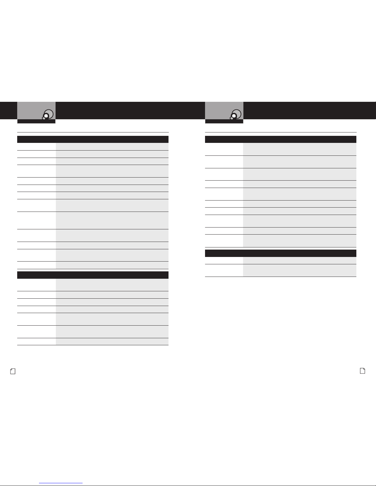
Specifications
•
General
Frequency Range 28.0 to 29.7 MHz
Frequency Control Phase Lock Loop (PLL) synthesizer
Frequency Stability 0.005%
Operating
Temperature Range
-22°F to 122°F (-6°C to + 50°C)
Antenna Impedance 50 ohms
Antenna Connector Standard SO 239 type
Microphone Plug-in dynamic with Press-To-Talk switch and coiled cord
Input Voltage 13.8 V DC nominal, 15.9 V max., 10.0 V min.
(positive or negative ground)
Current Drain Transmit: 8.0 A AM/FM 15A SSB@100W PEP
Receive (squelched): 0.5 A
Receive (maximum audio output): 1.2 A
Size 2
3
⁄8"(H) x 77⁄8"(W) x 103⁄4"(D)
[6cm (H) x 20cm (W) x 27.3cm (D)]
Weight 6.5 lbs.
Meter (3-in-1) Illuminated – indicates relative output power,
received signal strength, and SWR.
Built-in Speaker 4 watts
Transmitter
Power Output Low – 4 watts AM/FM 12 watts SSB
High – 30 watts AM/FM 100 watts PEP SSB
Frequency Response 300 to 3,000 Hz
Frequency Tolerance 500 Hz
Transmit Distortion 2%
Spurious Harmonic
Emission
-65 dB
Output Indicators Meter shows relative RF output power and SWR.
Transmit LED glows red when transmitter is in operation.
Antenna Warning LED Glows red when SWR is greater than 3.0.
Specifications
•
Receiver
Sensitivity AM: 0.5 µV for 10 dB S/N
FM/SSB/CW: 0.25 µV for 12 dB S/N
Audio Frequency
Response
300 to 3,000 Hz
Maximum Signal
to Noise Ratio
45 dB
Image Rejection 65 dB
Adjacent AM/FM: 60 dB
Channel Rejection SSB/CW: 70 dB
RF Gain Control (AGC) 40 dB – adjustable for optimum signal reception
Squelch Adjustable – threshold less than 0.5 µV
Automatic Noise
Limiter (ANL)
Switchable
Noise Blanker (NB) Switchable
Receive Indicators Meter shows relative signal strength.
Receive LED glows green when receiving a signal.
External Speaker
Power Output 4 watts into external speaker
External Speaker
(Not Supplied)
8 ohms
(Specifications subject to change without notice)
Your Mobile Radio Your Mobile Radio
5
Nothing comes close to a Cobra
®
Installation and Connection
4
English
Included in this Package
Your Mobile Radio Your Mobile Radio
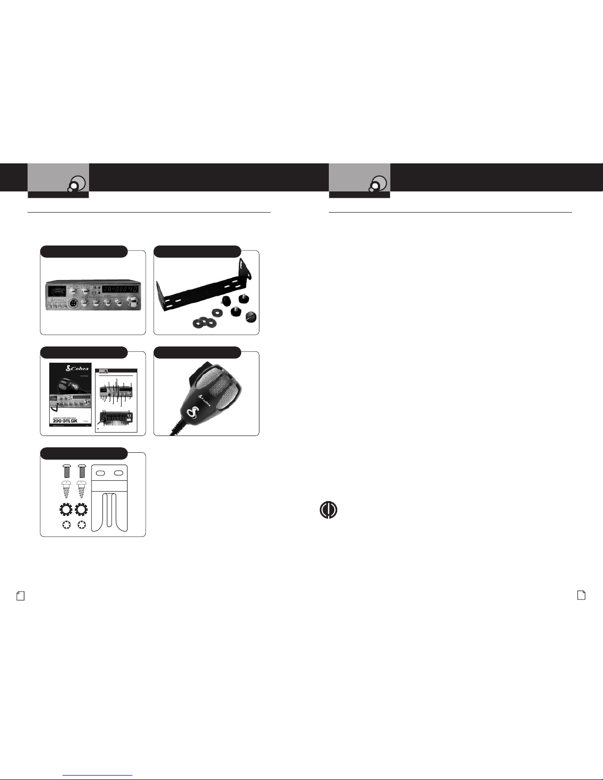
Included in this Package
•
You should find all of the following items in the package with your radio.
Installation and Connection
•
Refer to the illustration on page A2 for connection points on the back of the
unit while installing your radio.
--
4Location
Plan the location of the transceiver and microphone brackets before starting the installation.
Select a location that is convenient for operation and does not interfere with the driver or
passengers in the vehicle. In automobiles, the transceiver is usually mounted below the
dash panel, with the microphone bracket beside it.
--
4Mounting
Your mobile radio is supplied with a universal mounting bracket. When mounting the bracket
and radio to your car, make sure it is mechanically strong. Also provide a good electrical
connection to the chassis of the vehicle. Proceed as follows to mount the transceiver:
--
4Mount the Transceiver
1. After you have determined the most convenient location in your vehicle, hold the mobile
radio with the mounting bracket in the exact location desired. If nothing will interfere
with mounting it in the desired position, remove the thumbscrews and use the
mounting bracket as a template to mark the holes for the mounting screws. Before
drilling the holes, make sure nothing behind the surface will be damaged or interfere
with the installation.
2. Connect the antenna cable plug to the standard receptacle (ANT) on the rear panel.
Most antennas are terminated with a type PL-259 plug and mate with the receptacle.
3. Connect the red DC power input wire (with the fuse) to +13.8 V DC. This wire extends
from the rear panel. In automobile installation, connect directly to positive terminal
(red) of the vehicle's battery. We recommend that you install a fuse within six inches
of the battery.
4. Connect the black lead to -13.8 V DC to the negative (black) post of the battery.
5. Mount the microphone bracket on either side of the transceiver, using the two screws
supplied. When mounting in an automobile, place the bracket under the dash so the
microphone is readily accessible.
6. Attach the microphone cable to the connector on the face of the transceiver.
NOTE
If the radio is to be used to send Morse code, an optional telegraph
key will need to be connected to the CW Key Connector on the back
of the unit.
Transceiver Universal Mounting Bracket
Operating Instructions
Microphone
Microphone Bracket
A2
English
Controls and Indicators
Introduction
Controls and Indicators
•
Frequency
Selector
Echo
(center knob)
SWR CAL
(outer ring)
Analog
Meter
Antenna
Warning
Indicator
Band
A / B / C / D
CW / FM / AM /
USB / LSB
Dim /
SWR CAL
RX /TX
Indicator
SWR /
S/RF
Dual 7
Segment
Frequency
Display
Six Digit
Frequency
Display
Antenna
Connector
External
Speaker
Connector
Continuous
Wave Connector
Microphone
Connector
NB / ANL
High/Low Power
R Beep
+10
KHz
Microphone Gain
(center knob)
RF Gain
(outer ring)
Power Cord
Connector
Off / On / Volume
(center knob)
Squelch
(outer ring)
Clarifier Fine
(center knob)
Coarse
(outer ring)
 Loading...