


200GTL ALIGNMENT REVISION: 1.0 BURKE
ALIGNMENT PROCEDURE
Downloaded from www.cbradio.nl
MODEL: 200GTL
REVISION: 1.2
DATE: 02/14/06
PREPARED BY: BURKE
Total Pages: 6 pages
Page:1 print date: 9/23/09
200GTL ALIGNMENT REVISION: 1.0 BURKE
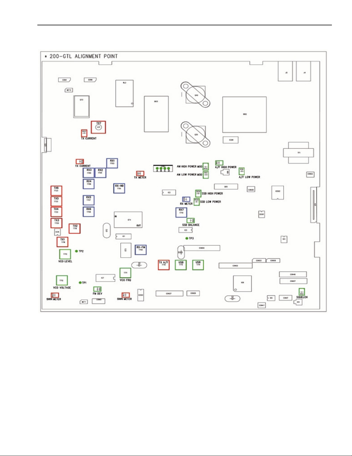
200GTL ALIGNMENT INSTRUCTION
1 TEST CONDITION:
1.0. TEST TEMPERTAURE: 77 ±9 °F
1.1. STANDARD DC POWER: 13.8VDC
1.2. STANDARD AUDIO LOADING: 8 Ω
1.3. ANTENNA IMPEDANCE: 50 Ω
1.4. STANDARD REF. MODULATION: AM 30%
FM 2.5KHz
1.5. PULSE GENERATOR: 1µS pulse @ 100mS and 1V peak-to-peak amplitude,
with rise and fall time of less than 10nS.
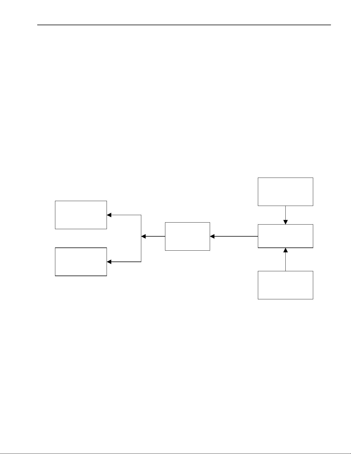
1.6. TEST EQUIPMENT SETUP AS BELOW:
A. TX test equipment setup:
Power
Supply
Modulation
Meter
RF
Wattmeter
Dummy
Load
200 GTL
Generator
Audio
Page:2 print date: 9/23/09

200GTL ALIGNMENT REVISION: 1.0 BURKE
RF Signal
B. RX test equipment setup:
AC
VTVM
Generator
Oscilloscope
200GTL
Power
Supply
8 ohm Load
Noise Pulse
Generator
2.0
MAIN ALIGNMENT
2.1 PLL Alignment
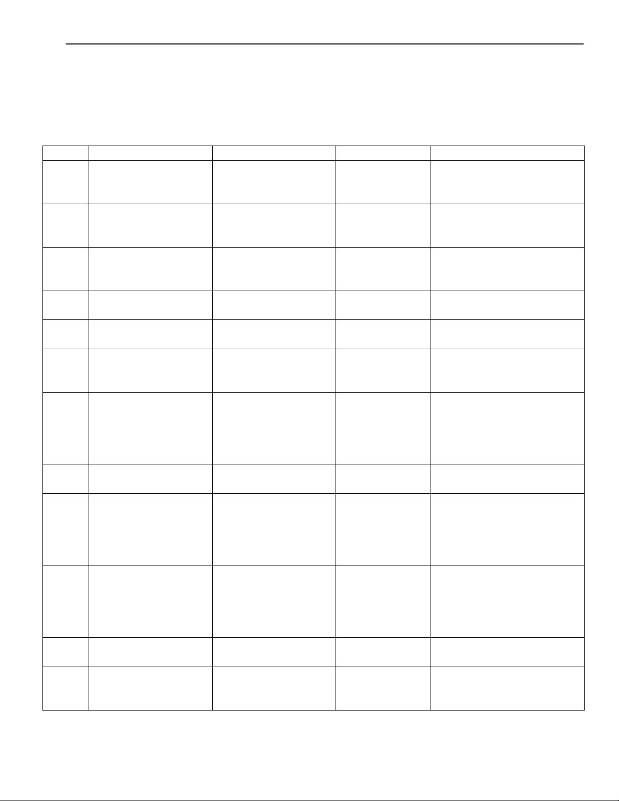
STEP PRESET TO CONNECTIONS ADJUST PROCEDURE
RX mode, AM,
1
28.000MHz
2 Same as step 1
3 Same as step 1
2.2 Carrier Alignment
STEP PRESET TO CONNECTIONS ADJUST PROCEDURE
TX mode, AM,
1
28.000MHz
RX mode, LSB,
2
28.000MHz
RX mode, USB,
3
28.000MHz
Oscilloscope to TP1
(junction of R92-C607)
Oscilloscope to TP2
(forward end of BF9)
Frequency counter to
TP2
(forward end of BF9)
Frequency counter to
TP3
Same as step 1 T714 Adjust for 10.6975MHz
Same as step 1 T715 Adjust for 10.6925MHz
T712
T713 Adjust for maximum output
T711
T716 Adjust for 10.695MHz
Check for range of 0.2 to
7VDC, then set to 2.8V
Adjust for 17.305MHz
(frequency – 10.695)
Page:3 print date: 9/23/09

200GTL ALIGNMENT REVISION: 1.0 BURKE
T703, T704,
T705, T706,
T707, T708,
modulation, RF output 1500µV
3.0 RECEIVER ALIGNMENT
Connect an AC VTVM with 8 ohm load across speaker coil.
Adjust volume control to obtain a suitable indication.
Set generator output low enough to prevent AGC limiting.
Preset controls as follows, unless otherwise noted:
RF Gain maximum, Squelch minimum, NB/ANL off.
STEP PRESET TO CONNECTIONS ADJUST PROCEDURE
Output of signal generator to
RX mode, AM
1
28.000MHz
Same as step 1,
2
squelch to
maximum
antenna connector.
Freq. = 28.000MHz, 1KHz 30%
modulation, RF output 1µV
Output of signal generator to
antenna connector.
Freq. = 28.000MHz, 1KHz 30%
T710
RV2
Adjust for maximum signal on
VTVM
SQUELCH RANGE
Adjust just until squelch opens
RX mode, AM
3
29.500MHz
(Band D)
RX mode, AM,
28.000MHz,
4
NB/ANL switch
set to NB/ANL
RX mode, FM,
5
28.000MHz
Output of signal generator to
antenna connector.
Freq. = 29.500MHz, NO
modulation, RF output 100µV
Output of signal generator and
noise pulse generator to antenna
connector.
Freq. = 28.000MHz, 1KHz 30%
modulation, RF output 1µV.
Oscilloscope to collector of Q6
Output of signal generator to
antenna connector.
Freq. = 28.000MHz, 2.5KHz
deviation, RF output 1µV
RV15
T701
T702
SIGNAL METER
Adjust for a reading of S-9 on the
analog meter of the radio
NOISE BLANKER
Adjust for maximum amplitude
on oscilloscope
Adjust for maximum signal on
VTVM
Page:4 print date: 9/23/09
200GTL ALIGNMENT REVISION: 1.0 BURKE
on
4.0 TRANSMITTER ALIGNMENT
Maintain a 50 ohm 25 watt dummy load on the antenna connector for the following steps.
Preset controls as follows, unless otherwise noted:
RF Power set to HI, Mic Gain to minimum.
STEP PRESET TO CONNECTIONS ADJUST PROCEDURE
1
TX mode, LSB,
29.700MHz
2 Same as step 1
3
4
5
TX mode, AM,
29.700MHz
TX mode, AM,
29.700MHz
Same as step 4,
Power switch to LO
TX mode, AM,
6
29.700MHz
Power switch to HI
TX mode, AM,
7
29.700MHz
Mic Gain to maximum
8
Same as step 7,
Power switch to LO
TX mode, FM,
9
29.700MHz
Mic Gain to maximum
TX mode, LSB,
10
29.700MHz
Mic Gain to maximum
11
Same as step 10
Power switch to LO
TX mode, LSB,
12
29.700MHz
Mic Gain to minimum
Insert a current meter
between pins A(+) and
RV21
B(-) of CON3
Insert a current meter
between pins C(+) and
RV19
D(-) of CON3
RF wattmeter to
antenna connector
RF wattmeter to
antenna connector
T718, T719,
T720, T721,
T722, T723, L21
RV9
Same as step 4 RV8
RV1
Modulation meter to
antenna connector.
Insert a 1KHz, 30mV
RV12
signal to microphone
input.
Same as step 7 RV3
Deviation meter to
antenna connector.
Insert a 1KHz, 30mV
RV5
signal to microphone
input.
RF wattmeter to
antenna connector.
Insert a 1KHz, 30mV
RV14
signal to microphone
input.
Same as step 10 RV20
Oscilloscope to
antenna connector.
RV6 Adjust for minimum output
BIAS CURRENT
Adjust for 1.3 amps
BIAS CURRENT
Adjust for 60mA
Adjust for maximum RF
output
RF POWER – HI
Adjust for 32 watts
RF POWER - LO
Adjust for 4 watts
RF POWER METER
Adjust for a reading of S-7
the analog meter of the radio
AMC CONTROL - HI
Adjust for 90% modulation
AMC CONTROL - LO
Adjust for 90% modulation
DEVIATION LIMITER
Adjust for 2.9KHz deviation
SSB POWER – HI
Adjust for 100 watts
SSB POWER – LO
Adjust for 12 watts
Page:5 print date: 9/23/09

200GTL ALIGNMENT REVISION: 1.0 BURKE
TRANSMITTER ALIGNMENT (continued)
STEP PRESET TO CONNECTIONS ADJUST PROCEDURE
SWR METER
13
TX mode, AM,
Power switch to HI,
Mic Gain to minimum,
S/RF switch set to
CAL
Connect a 100 ohm
dummy load to the
antenna connector
RV23
Adjust SWR Cal knob so
analog meter on radio goes
to CAL mark. Then set
S/RF switch to SWR and
adjust RV23 for an SWR
reading of 2 on the analog
meter of the radio.
SWR METER
14
Same as step 13
Power switch to LO
Same as step 13 RV7
Same as step 13 except
adjust RV7 for a reading of 2
on the analog meter
15
TX mode, AM,
Power switch to LO,
Mic Gain to minimum
Short the antenna
output to ground
RV4
ANTENNA LIGHT
Adjust RV4 until the antenna
light just comes on
Page:6 print date: 9/23/09
200GTL ALIGNMENT REVISION: 1.0 BURKE
Page:7 print date: 9/23/09

200GTL ALIGNMENT REVISION: 1.0 BURKE
REVISION HISTORY
1.0 – Initial release.
1.1 – Corrected step 2 in section 2.2 (changed USB to LSB).
Corrected step 3 in section 2.2 (changed LSB to USB).
1.2 – Added Step 15 in Section 4
Page:8 print date: 9/23/09

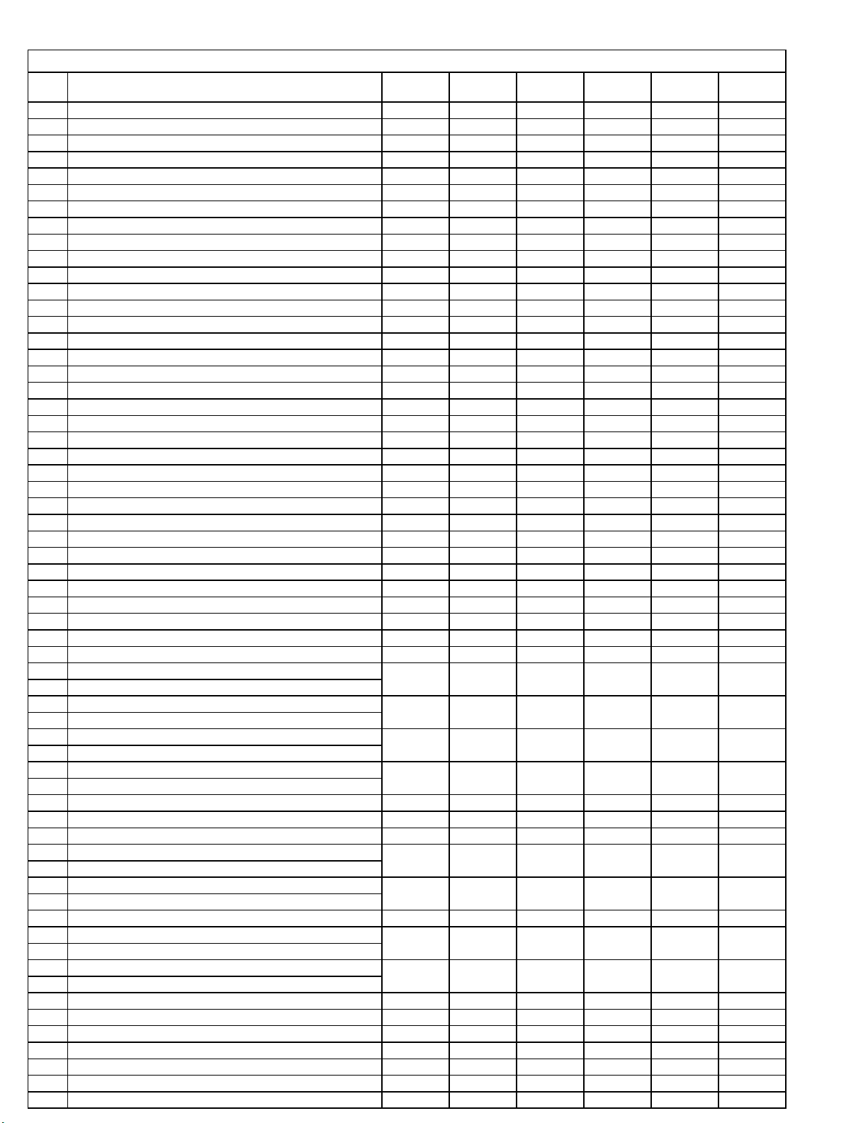
TEST CONDITION:
RX TESTING
SUPPLY VOLTAGE: 13.8 V
BAND A ( 28.000 MHz)
PIN
NO.
1 V 0 0 0 0 0
2 V 2.37 2.37 2.37 2.37 2.37
3 V 2 2 2 2 2
4 V 4.9 4.9 4.9 4.9 4.9
5 N.C. N.C. N.C. N.C. N.C.
6 N.C. N.C. N.C. N.C. N.C.
7 V 0 0 0 0 0
8 N.C. N.C. N.C. N.C. N.C.
9 V 0 0 0 0 0
DURING STANDBY
WHEN CH. SW. TURN ON TO DOWN POSITION
10 V 4.9 4.9 4.9 4.9 4.9
11 V 0.44 0.44 0.44 0.44 0.44
12 V 0 0 0 0 0
DURING STANDBY
DIM SWITCH FUNC. TURN ON
13 V 4.86 4.86 4.86 4.86 4.86
14 V 4.86 4.86 4.86 4.86 4.86
15 mV 13.6 13.6 13.6 13.6 13.6
16 mV 13.8 13.8 13.8 13.8 13.8
17 N.C. N.C. N.C. N.C. N.C.
18 V 0 0 0 0 0
DURING STANDBY
WHEN CH. SW. TURN ON TO UP POSITION
19 V 0 0 0 0 0
STANDBY
WHEN ROGER BEEP SW ITCH TURN ON
20 mV 20.6 20.6 20.6 20.6 20.6
21 mV 17.6 17.6 17.6 17.6 17.61
22 mV 3.1 3.1 3.1 3.1 3.1
DURING STANDBY
WHEN 10KHZ SWITCH TURN ON
23 V 4.9 4.9 4.9 4.9 4.9
24 mV 20.9 20.9 20.9 20.9 20.9
25 V 4.96 4.96 4.96 4.96 4.96
26 mV 45.6 45.6 45.6 45.6 45.6
27 N.C. N.C. N.C. N.C. N.C.
28 V 6.8 0 0 0 0
MODE SWITCH SET TO CW
29 V 4.96 4.96 4.96 4.96 4.96
30
BAND SWITCH SET TO A BAND / WHEN SET TO
OTHER BAND PIN IS EQUAL TO ZERO VOLT
31
BAND SWITCH SET TO B BAND / WHEN SET TO
OTHER BAND PIN IS EQUAL TO ZERO VOLT
32
BAND SWITCH SET TO C BAND / WHEN SET TO
OTHER BAND PIN IS EQUAL TO ZERO VOLT
33
BAND SWITCH SET TO D BAND / WHEN SET TO
OTHER BAND PIN IS EQUAL TO ZERO VOLT
34
35
NO CW JACK INSERTED
36
BOTH COARSE & FINE VR AT CENTER POSITION
VR COARSE AT CENTER & FINE VR IN MINIMUM
POSITION
FINE VR AT CENTER & COARSE VR IN MINIMUM
POSITION
BOTH COARSE & FINE VR AT MINIMUM POSITION
FINE VR AT CENTER & COARSE VR IN MAXIMUM
POSITION
COARSE VR AT CENTER & FINE VR IN MAXIMUM
POSITION
BOTH FINE & COARSE VR AT MAXIMUM POSITION
37 N.C. N.C. N.C. N.C. N.C.
38 mV 27.4 27.4 27.4 27.4 27.4
39 V 4.36 4.36 4.36 4.36 4.36
40 V 4.83 4.83 4.83 4.83 4.83
41 V 0 0 0 5.31 0
MODE SWITCH SET TO USB MODE
42 V 0 0 0 0 5.4MODE SWITCH SET TO LSB MODE
SWITCH CONDITION
UNIT CW FM AM USB LSB
V 4.7 4.7 4.7 4.7 4.7
V 4.4 4.4 4.4 4.4 4.4
V 4.7 4.7 4.7 4.7 4.7
V 4.7 4.7 4.7 4.7 4.7
V 4.7 4.7 4.7 4.7 4.7
V
V
V
V
V 0 0 0 0 0
V 4.96 4.96 4.96 4.96 4.96
V 2 2 2 2 2
V 1.8 1.8 1.8
V 0.62 0.62 0.62 0.62 0.62
V 3.7
V 2.3 2.3 2.3
V 3.94 3.94 3.94 3.94 3.94
4.75 4.75 4.75 4.75 4.75
4.75 4.75 4.75
4.75 4.75 4.75 4.75 4.75
4.75 4.75
0.65 0.65 0.65V
3.7 3.7
4.75
4.75 4.75
4.75 4.75
1.8 1.8
0.65 0.65
3.7 3.7
2.3 2.3
 Loading...