

Page 1

Page 2
For parts orders contact your local dealer
To locate your closest Cobra dealer
log on to
www.cobramotorcycle.com
or call
(517) 437-9100
If you need technical assistance
contact your local dealer or call
the Cobra Technical Support Hotline at
(517) 437-9100
Cobra Motorcycle MFG., Inc.
240 Uran Street
Hillsdale, Michigan 49242
Page 3
DISCLAIMER OF WARRANTY
This motorcycle is sold “as is” with all faults, obvious or not. There are no warranties
expressed or implied, including any warranty of merchantability and warranty of fitness
for any particular purpose.
“WARNING”
THE COBRA ECX70 IS A COMPETITION MODEL ONLY AND IS NOT
MANUFACTURED FOR, NOR SHOULD IT BE USED ON PUBLIC STREETS, ROADS
OR HIGHWAYS.
THE USE OF THIS ATV SHOULD BE LIMITED TO PARTICIPATION IN SANCTIONED
COMPETITION EVENTS UPON A CLOSED COURSE BY A SUFFICIENTLY SKILLED
RIDER AND SHOULD NOT BE USED FOR GENERAL OFF-ROAD RECREATIONAL
RIDING.
IMPROPER USE OF THIS MOTORCYCLE CAN CAUSE INJURY OR DEATH.
THIS BIKE IS INTENDED FOR EXPERIENCED RACERS ONLY AND NOT FOR
BEGINNERS.
IT IS YOUR RESPONSIBILITY AS THE OWNER OF THIS COBRA PRODUCT OR AS
THE PARENT, OR LEGAL GUARDIAN OF THE OPERATOR, TO KEEP THIS COBRA
PRODUCT IN PROPER OPERATING CONDITION.
THIS ATV WAS DESIGNED FOR RIDERS THAT WEIGH LESS THAN 110 LBS WITH
FULL RIDING GEAR AND SHOULD NOT BE OPERATED BY RIDERS THAT WEIGH
MORE THAT.
BE SURE THAT THE RIDER ALWAYS WEARS ADEQUATE SAFETY GEAR
EVERYTIME HE OR SHE RIDES THEIR COBRA ATV.
IMPORTANT SAFETY NOTICE
Failure to follow WARNING instructions could result in severe injury or death to
the machine operator, a bystander, or a person inspecting or repairing the
machine.
CAUTION:
A CAUTION indicates special precautions that must be taken to avoid damage to
the machine.
NOTE:
A NOTE provides key information to make procedures easier or clearer.
MCE72007 2
Page 4

Table Of Contents
General Information..............................................................................................3
Specifications - General....................................................................................3
Specifications - Torque Values..........................................................................4
Optional Suspension Components....................................................................5
Starting Procedure ............................................................................................8
General Tips......................................................................................................9
Maintenance .......................................................................................................10
Schedule & Tips..............................................................................................10
M1: Replacing Transmission Lubricant ...........................................................10
M2: Chain adjustment .....................................................................................11
M3: Air Filter Cleaning.....................................................................................12
M4: Front end..................................................................................................14
Toe in adjustment........................................................................................14
Steering .......................................................................................................14
Parts ...................................................................................................................15
Parts – Air Inlet System...................................................................................15
Parts – Bars and Steering ...............................................................................16
Parts – Bumper, Nerf & Grab Bars..................................................................17
Parts – Carburetor...........................................................................................18
Parts – Clutch Actuation..................................................................................19
Parts – Coolant System...................................................................................20
Parts – Electrical System ................................................................................21
Parts – Engine Clutch......................................................................................22
Parts – Engine – Clutch / Kick Cover...........................................................23
1
Page 5

Parts - Engine - Ignition Side.......................................................................24
Parts - Engine – Kick Mechanism................................................................25
Parts – Engine – Shift Mechanism...............................................................26
Parts – Engine – Top End............................................................................27
Parts - Engine - Transmission......................................................................28
Parts – Exhaust System..................................................................................29
Parts - Front A-Arms & Steering Upright.........................................................30
Parts – Front Brakes .......................................................................................31
Parts – Front Shock.........................................................................................32
Parts – Miscellaneous.....................................................................................33
Parts – Plastic Bodywork & Seat.....................................................................34
Parts – Rear Brake..........................................................................................35
Parts – Rear Drive...........................................................................................36
Parts – Rear Shock.........................................................................................37
Parts – Swingarm Assembly............................................................................38
Parts – Tie Rod Assembly...............................................................................39
Engine Parts / Service ........................................................................................40
Engine Service................................................................................................40
Base Gasket Selection ................................................................................41
Fuel & Air System............................................................................................43
Reeds ..........................................................................................................43
Carburetor Cleaning ....................................................................................44
Exhaust ...........................................................................................................45
Tuning.................................................................................................................45
Carburetor.......................................................................................................45
Jetting Decisions..........................................................................................45
Troubleshooting..................................................................................................48
2
Page 6

General Information
Specifications - General
Items ECX70
Dimensions
Wheelbase 42” (1067mm)
Width Front / Rear 43” / 46” (1092mm / 1168mm)
Weight 210 lb
Engine
Type 2-stroke, single cylinder, reed valve
Cooling system Liquid-cooled
Displacement 64.8 cc (3.95 Cubic inches)
Bore and stroke 44.5 mm x 44.7 mm
Ignition system Digital Electronic
Spark plug Champion 8339
Gap 0.023” – 0.025” (0.58 – 0.64 mm)
Fuel type 93 octane pump gasoline
Oil type
Fuel / oil mix ratios 32:1
Ignition timing .050” (1.3mm) BTDC
Carburetion 26mm Mikuni VM
Main jet 190
OTHER RACE FUELS ARE NOT RECOMMENDED
Cobra Venom 2-cycle Race Oil
Slow (Pilot) jet 50
Jet needle 5F21, 4th position from the top
Float height
Transmission
Speed Six speed
Clutch Manual hydraulic
Final drive ratio 13/48 T
Transmission / clutch oil type
Cobra Power Shift Transmission Lubricant
Quantity 530 ml (18 oz)
3
Page 7
Chassis
Tire Pressure front / rear (7 psi / 5 psi)
Travel, front / rear 240mm / 247mm (9.4” / 9.7”)
Race sag, front / rear 96mm / 99mm (3.8” / 3.9”)
Free sag, front / rear 38mm / 40mm (1.5” / 1.6”)
Specifications - Torque Values
ENGINE Fastener
Torque Value
ft-lb in-lb Nm
Size &
Remarks
Cylinder head nuts 14 170 19 7mm
Engine oil drain 3 36 4 8 x 1.25
Engine oil fill 2 24 2.7 14 x 1.0
Spark Plug (SP) (SP) (SP) 14 x 1.25
Crank case half 5 60 6.8 6 x 1.0
Crank case cover 5 60 6.8 6 x 1.0
Flywheel rotor nut 40 480 54 10 x 1.25 (G)
Clutch hub 40 480 54 10 x 1.25 (G)
Units of mm unless otherwise specified
(G) denotes the use of wicking / bearing retainer (green) thread locking agent to
applied to the mating surfaces of the two components but not the threads.
(SP) To apply the proper torque to the spark plug when inserting, one must first
screw the spark plug in until the metal gasket ring causes resistance and then
turn another 1/8 to ¼ turn.
4
Page 8
CHASSIS Fastener
Torque Value
ft-lb in-lb Nm
Size &
Remarks
Handle bar mounts 15 177 20 8 x 1.25
Handle bar clamps 15 177 20 8 x 1.25
Front engine mount 22 265 30 8 x 1.25
Rear brake lever pivot 10 120 13.6 8 x 1.25
Upper shock mount 40 480 54 10 x 1.5
Lower shock mount 40 480 54 10 x 1.5
Swingarm pivot 75 900 102 14 x 2.0
Units of mm unless otherwise specified
(R or G) designates that the application requires the use of high strength (red or
green) thread locking agent applied to the threads.
(B) designates that the application requires the use of medium strength (blue)
thread locking agent applied to the threads.
Optional Suspension Components
Front shock springs
Weight of Rider (lb) Helper Main
Less than 65
65 to 100
Greater than 100
Rear shock springs
Weight of Rider (lb) Helper Main
Less than 65
65 to 100
Greater than 100
SCEX0065P (SILVER,
65 LB/IN)
SCEX1080 (RED, 80
LB/IN)
SCEX1095 (YELLOW,
95 LB/IN)
SCEX1150 (GREEN,
150 LB/IN)
SCEX0175P (BLACK,
175 LB/IN)
SCEX0200P SILVER
(200 LB/IN)
SCEXA135 (BLUE, 135 LB/IN)
SCEXA145 (RED, 145 LB/IN)
SCEXA155 (YELLOW, 165
LB/IN)
SCEX025P (BLUE, 425 LB/IN)
SCEX0450P (GREEN, 450 LB/IN)
SCEX0475P (BLACK, 475 LB/IN)
Spring Rate
Helper
Color Part Number
(lb/in)
65 Silver SCEX0065P
5
Page 9

Fox 8” long main
80 Red SCEX1080
95 Yellow SCEX1095
110 White SCEDX1110
125 Gold SCEX1125
150 Green SCEX1150
175 Black SCEX0175P
200 Silver SCEX0200P
250 Red SCEX0250P
300 Yellow SCEX0300P
350 White SCEX0350P
spring (front)
Fox 7” long main
105 Orange SCEX1105
115 Green SCEX1115
125 White SCEX2125
135 Blue SCEX1135
145 Red SCEX1145
155 Yellow SCEX1155
165 Black SCEX1165
spring (rear)
300 Red SCEX1300
315 Yellow SCEX1315
330 White SCEX1330
350 Red SCEX1350
375 White SCEX1375
400 Yellow SCEX1400
425 Blue SCEX0425P
450 Green SCEX0450P
475 Black SCEX0475P
500 Purple SCEX0500P
Spring rate chart for Cobra Fox quad shocks
6
Page 10

Break-In Procedure
Your Cobra Motorcycle is a close-tolerance high performance machine and
break-in time is very important for maximum life and performance. The ECX70
can be ridden hard after the first ½ hour break-in time but it is recommended that
no adjustments are made to the carburetion or suspension until the full 8 hours of
bike break-in has elapsed. Also, after the engine, transmission, and drive train
have been broken-in for the full 8 hours, the bike will be faster!
Use a fuel / oil mixture of 32:1 for the full 8 hour break-in period. Be sure to use
93 octane pump gas, or Sunoco MO2
, with Cobra’s specially formulated Cobra
X
Venom 2-cycle Race Oil. (Part # MCMUOL02)
CAUTION:
Failure to use proper fuel or oil may result in premature engine wear, or damage
to the machine.
Adhering to the following break-in schedule will result in long lasting high
performance machine.
• First 5 minute period, operate the bike in neutral with a combination of idle
and high RPM operation. (avoid prolonged high RPM rev it good at least
once or twice per minute)
• Allow the engine to cool
• Ride for 15 minutes maximum, avoiding prolonged high RPM operation.
• Cool and inspect bike for loose fasteners.
• Next ½ hour of operation, avoid prolonged operation at Wide Open Throttle.
• After 1 hour of operation
o Check for loose bolts and nuts on the bike and retighten as
necessary (proper toque values are listed under Specifications).
o Clean the carburetor bowl.
o Change the transmission / clutch lubricant with Cobra Power Shift
Transmission Lubricant
o Replace the fuel filter.
• After 8 hours of operation have a Certified Cobra Mechanic change the
shock oils.
• Your bike is now ready for the highest level of competition!
7
Page 11

Starting Procedure
Before starting the machine inspect the following:
• Insure that the fuel tank contains an adequate volume of fuel / oil mixture to
complete the distance required. (93 octane pump gas with Cobra’s specially
formulated Cobra Venom 2-cycle Race Oil)
• Check for proper tire pressure in both tires.
• Observe the chain tension and adjust if necessary.
• Observe the coolant level and fill if necessary.
• Observe the level of lubricant in the transmission and add Cobra Power
Shift Transmission Lubricant if necessary.
• Verify that the chain rollers do not have improper wear.
• Inspect the frame, for;
o Cracks in the metal.
o Cracking paint which might indicate overly stressed material.
• Verify that the handlebars are tight.
• Check the throttle for;
o Smooth operation and sound closing.
o Frayed strands of the cable inside the throttle housing.
• Check for loose bolts and nuts, and re-torque as necessary.
• Verify that the air filter is clean and properly saturated with oil.
• Turn the fuel on by rotating the fuel petcock knob to the vertically downward
position (reserve position is horizontally inward).
CAUTION:
For best results from your Cobra ATV use only the recommended fuels. Testing
has shown that most ‘race’ fuels actually degrade performance.
When your pre-ride inspection is complete the bike may be started. For a cold
engine follow this procedure.
1. Reaching down to the carburetor, on the left side of the bike, push down on
the black choke lever.
2. Kick start the engine.
3. Rev the engine in short spurts, turning the throttle no more than 1/4 open
until the engine will run without the choke.
4. Verify a functional engine shut-off switch by shutting off the engine.
5. Restart the engine and proceed with riding when the engine is sufficiently
warm (i.e. the side of the cylinder is warm to touch).
CAUTION:
Never rev an engine full throttle when it's cold or slightly warmed up. Cobra
recommends that you tell your child to take it easy the first couple of minutes in
practice until the engine comes up to full operating temperature. Make sure your
engine is properly warmed up before racing.
8
Page 12

General Tips
1. Always wear a helmet and other protective riding gear.
2. Cobra recommends that you tell your child to take it easy the first couple of
minutes in practice until the engine comes up to full operating
temperature.
3. Make sure your riders’ foot is not resting on the rear brake pedal while they
are riding
4. Evaluate the bikes jetting only after it has been warmed up to race
temperatures.
5. A properly maintained machine is safer, faster, and more fun to ride.
6. When washing the bike, be careful to not directly aim the hose at the air
filter area.
7. Mare sure that there is adequate free play in both the front lever and rear
brake pedal.
8. Your Cobra ATV has a 10 digit VIN (Vehicle Identification Number). The
first three digits indicate the model and the seventh indicates the model
year (MY).
.
a. Example, ECXxxx7xxx is a 2007 MY ECX70.
9
Page 13

Maintenance
Schedule & Tips
It is important that you adhere to this maintenance schedule so as to promote the
longevity of your Cobra Motorcycle.
• Between each ride
o Inspect the fuel filter for contaminates.
o Check the air filter (clean and re-oil as necessary).
o Insure the smooth operation of the throttle cable (throttle soundly
‘clacks’ shut).
o Check for frayed strands of the throttle cable inside the throttle housing
and replace if necessary.
o Check for adequate tire pressures and adjust if necessary.
o Check all nuts and bolts for proper torque and re-torque if necessary.
o Spray all moving parts with WD40 or other light oil.
o Check drive chain for
Proper tension and adjust if necessary.
Adequate lubrication and lubricate if necessary.
o Check the frame for cracks in the metal or cracks in the paint that
might indicate that the metal has been stressed beyond it’s safe limits.
Replace or get properly rewelded as necessary.
• Every 2 hours of operation
o Replace the transmission oil with Cobra Power Shift Transmission
Lubricant.
• Every 10 hours of operation
o Have the shock oil replaced by a Certified Cobra Mechanic.
CAUTION:
1. If you ever need to weld anything on the bike, disconnect the spark plug
cap, unplug the ignition, disconnect the kill switch, scrape the paint bare
near the area to be welded and put the ground clamp as close to the area
to be welded as possible.
Be sure the fuel tank and carburetor have been removed and safely located
away from the welding process.
2. The frame is a low carbon alloy tubing and it is important to weld it with the
proper rod and heat settings set as light as possible. Cobra recommends
replacing the frame with a new one if the old one becomes damaged.
M1: Replacing Transmission Lubricant
10
Page 14
Tools needed:
• 530 ml (18 oz) Cobra Power Shift Transmission Lubricant
• large flat blade screwdriver
• 13 mm wrench or socket
Procedure:
1. Begin this procedure with a bike that has been ridden more than 5 minutes
but less than 10 minutes. It is desired to have the engine warm enough so
that the oil ‘runny’ but not so hot that there is risk of being burned by the
engine or the oil.
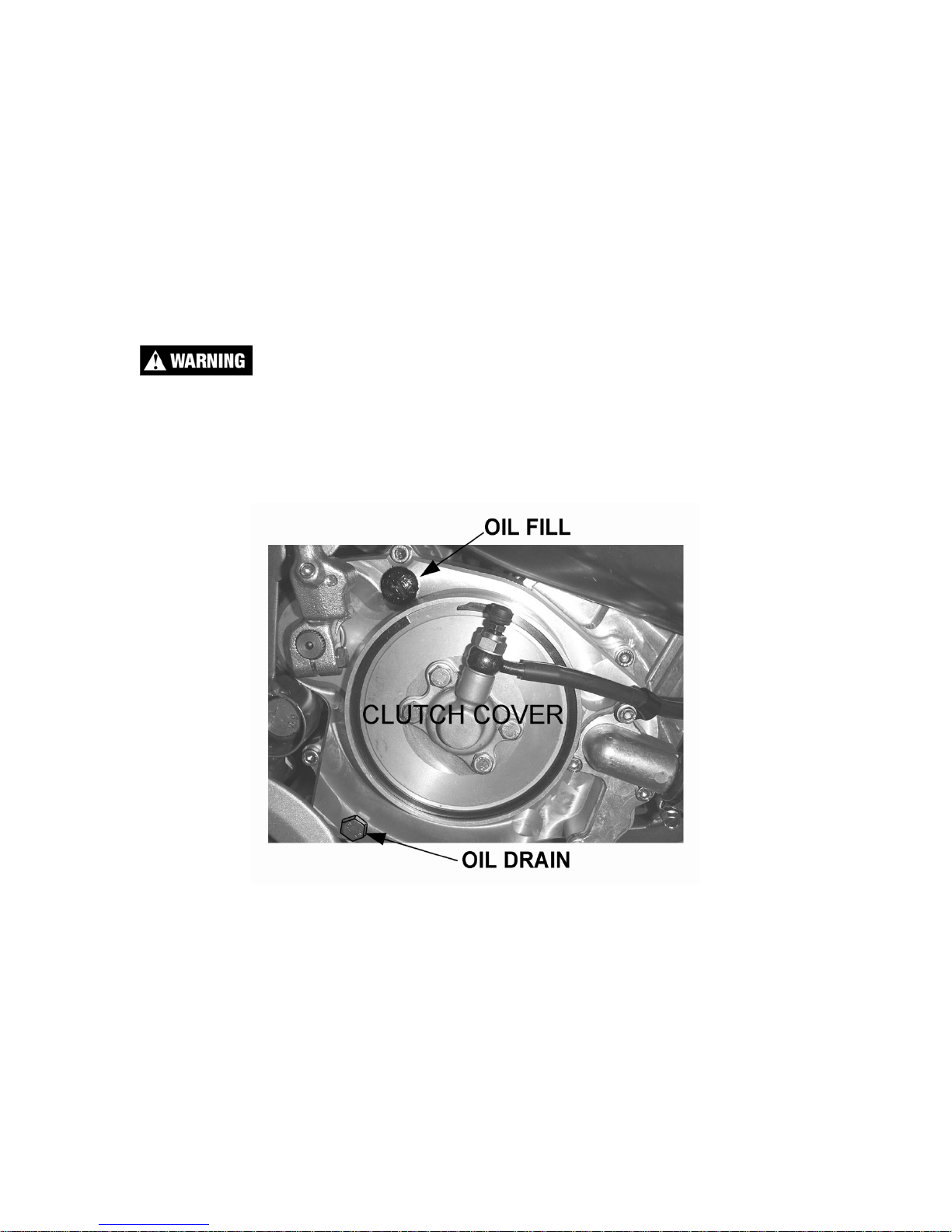
Hot oil and hot components on the motorcycle may cause burns.
2. Lean bike against something or set on stand with oil drain hole.
3. Using the 13 mm wrench, remove the oil drain bolt located on the right side
of the engine (figure 1).
4. After it has drained, reinstall the drain screw with gasket.
5. Remove the oil fill plug and pour in 530 ml (18 oz) 85W 90 gear lubricant.
NOTE: Leaning the bike over onto it’s left hand side will facilitate the oil filling
procedure.
6. Reapply the oil fill screw, securely, being sure the gasket is in place.
M2: Chain adjustment
Tools needed:
Figure 1
11
Page 15
• 13 mm wrench or socket
• 5mm pin (Screw driver or hex key will do)
Procedure:
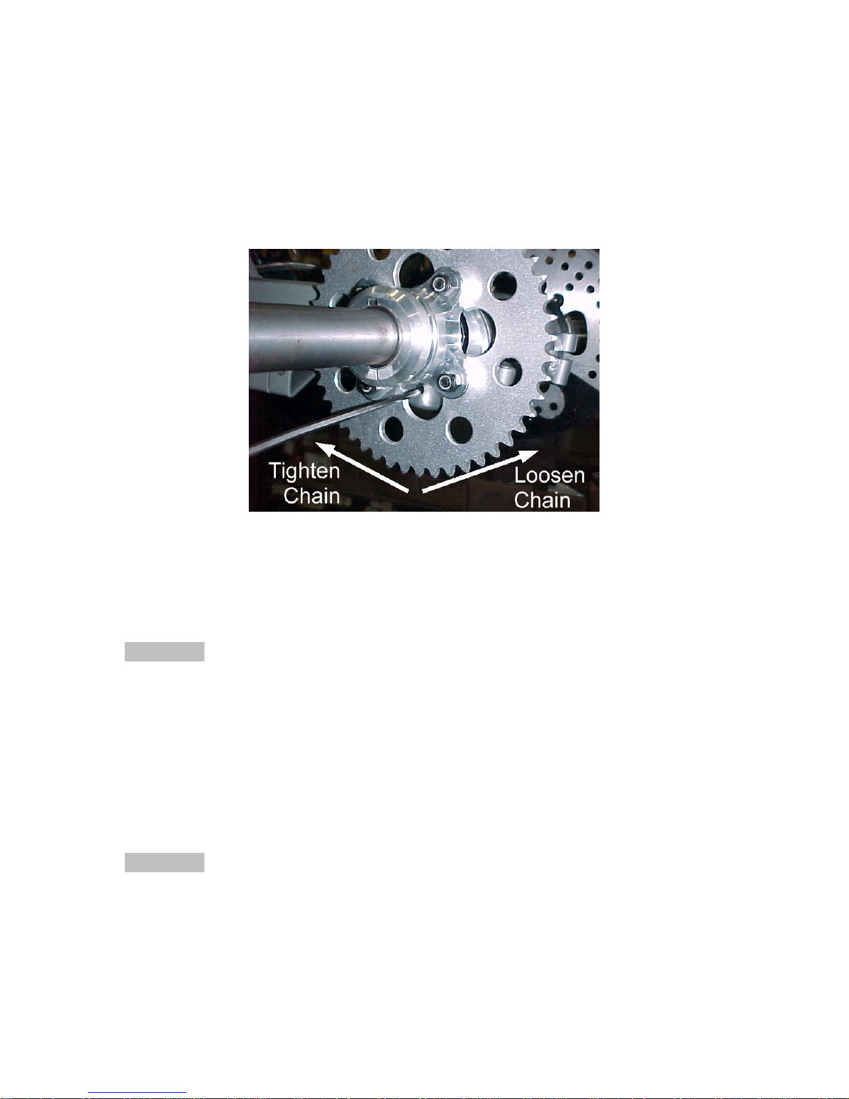
1. Loosen the eccentric housing on the swingarm with two 13mm tools.
2. Stick the 5mm pin through the sprocket into the eccentric hole.
3. Push the quad forward or backward, turning the wheels (i.e. the sprocket) in
the direction shown until the desired chain tension is achieved (see fig. 2).
NOTE:
The location of the pin hole is the ‘fattest’ part of the eccentric. Restated, if the
pin hole is all the way forward, the chain is as tight as possible, and if the pin hole
is all the way back, the chain is as loose as possible.
CAUTION:
Proper chain tension allows no less than ½” (12mm) free play through out the
range of rear suspension travel.
NOTE:
It may be handy to set backwards on the seat and feel the chain as you weight,
and unweight, seat to feel for chain free play.
4. After achieving the proper adjustment retighten the two eccentric pinch
bolts.
CAUTION:
Be sure to remove the pin from the eccentric before riding.
Figure 1
M3: Air Filter Cleaning
This Cobra Motorcycle comes with a unique air filter / air boot unit designed to
facilitate motorcycle service.
12
Page 16

Tools recommended for air filter maintenance:
• Srewdriver
• Foam filter oil
Procedure
1. Removed the filter from the carburetor.
2. Clean the filter with cleaning solvent and then again with hot soapy water.
3. Allow it to dry thoroughly.
4. Saturate with foam filter oil and remove excess.
Do not clean the air filter with gasoline or other highly volatile petroleum product.
Cleaning solvent, diesel fuel, or kerosene would be preferred but caution should
still be taken.
NOTE:
The biodegradable air filter oils, greases, and cleansers work acceptably with this
Cobra Motorcycle.
NOTE:
It is very important to keep the air filter clean and properly oiled with high quality
water-resistant foam filter oil. It’s very important to oil your filter consistently each
time because varied amounts of oil will change your carburetor jetting.
NOTE:
Make sure you change or clean your filter after each moto or significant ride. We
recommend carrying three or more filters in your toolbox.
• 1 for practice
• 1 for each moto
CAUTION:
Dusty conditions will require more frequent cleaning.
13
Page 17

M4: Front end
Toe in adjustment
Riders and parents have provided feedback that they prefer the toe in adjustment
between ½” (12mm) out to ½” (12mm) in. This is set by adjusting the length of
the tie rod assemblies. See figure 3 for direction of turn.
Adjust both wheels so that they have the same amount of toe in.
Figure 3
Steering
The unique Cobra front end will exhibit some free play from the factory and that
the seals (it that’s what you want to call them) will fall out after the first ride. We
have found that this causes no adverse effects and that the looseness does not
get significantly worse as long as the bearings are sprayed with a spray lubricant
(WD40 or similar) upon each ride.
14
Page 18

Parts
Parts – Air Inlet System
Figure 4
REF # PART # DESCRIPTION
1 RCDC0001 AIR FILTER ASSEMBLY
2 MCKGHO03 HOSE CLAMP – FILTER TO CARB
3 RAEX0026 CARBURETOR 26MM MIKUNI VM
4 MCMUCL10 HOSE CLAMP – CARB TO INLET BOOT (WIDE)
5 ECEX0012 INLET BOOT
6 MCMUCL03 HOSE CLAMP – BOOT TO REED MANIFOLD (NARROW)
7 ECDC0094 INLET MANIFOLD WITH REED ASSEMBLY
REEDS - REMPLACMENT STOCK
ECDCRD15 REEDS – SOFT
8 HCBC0602 M6 X 20 SOCKET HEAD CAP SCREW (4 REQ’D)
9 ECDC0093 GASKET – INLET (2 PLACES)
10 RCMU0001 SPACER – REED
11 FCEX0016 THROTTLE, QUAD THUMB STYLE
12 FCPW0004 THROTTLE CABLE END GROMMET
13 RCEX0002 CABLE - THROTTLE
14 RCE50001 FUEL LINE 5 INCH
15 FCDC0093 FILTER, FUEL
16 RCEX0019 COVER, AIR FILTER
17 RCMU0415 CABLE ADJUSTER CAP
RCMU0022 CARBURETOR VENT HOSE
Coolant System
15
Page 19

Parts – Bars and Steering
Figure 5
Bars and Steering
REF # PART # DESCRIPTION
1 FAEX0020 STEERING STEM
2 TCEX0009 HANDLEBAR - QUAD
3 FCEX0011 STEERING STEM BLOCK (2 REQ’D)
4 MCEXBR07 STEERING STEM BUSHING – SPLIT
NOT SHOWN
5 TCMU0404 BAR MOUNT KIT, SHORT – REPLACEMENT (2 REQ’D)
NOT SHOWN
6 HCBC0806 SOCKET HEAD CAP SCREW M8 X 30 (4 REQ’D)
7 HCBC1001 M10X45 SOCKET HEAD CAP SCREW (2 REQ’D)
8 HCNL1001 M10 LOCK NUT (2 REQ’D)
9 HCWF0801 8MM FLAT WASHER
10 HCBH0810 8MM X 65 HEX HEAD BOLT (2 REQ’D)
11 HCNL1001 10MM LOCK NUT
12 HCWF0010 10MM FLAT WASHER
13 MCEXBR04 STEM PIVOT BUSHING - LOWER
14 MCMU0001 CROSS BAR PAD
15 TCEX0013 GRIPS SET OF TWO
16 HCBH0601 6MM X 16 HEX HEAD BOLT (2 REQ’D)
17 HCNS0601 6MM NUT (2 REQ’D)
ZCEX0002 O’RING – STEERING STEM SEAL (2 REQ’D)
TCMU0403 BAR MOUNT KIT, TALL – OPTIONAL (2 REQ’D)
16
Page 20

Parts – Bumper, Nerf & Grab Bars
Figure 6
BODY PROTECTION
REF #
1 FCEX0024 NERF BARS (LEFT & RIGHT)
FCEX0067B NERF NET SET (BLACK)
FCEX0067R NERF NET SET (RED)
FCEX0067Y NERF NET SET (YELLOW)
NOT SHOWN
NOT SHOWN
NOT SHOWN
NOT SHOWN
2 FAEX0099 FRONT BUMPER
3 HCBB0802 M8 X 20 BUTTON HEAD BOLT (4 REQ’D)
4 FCEX0003 GRAB BAR
5 HCBC0820 M8 X 20 SOCKET HEAD CAP SCREW (4 REQ’D)
PART # DESCRIPTION
HCBH0808 8MM X 30 HEX HEAD BOLT (FRONT MOUNT, 2 PLACES)
HCBH0809 8MM X 50 HEX HEAD BOLT (REAR MOUNT, 2 PLACES)
HCWF0801 8MM FLAT WASHER (2 REQ’D)
HCNL0801 8MM LOCKNUT (2 REQ’D)
17
Page 21

Parts –
Carburetor
Figure 7
Carburetor accessories
REF # PART # DESCRIPTION
RAEX0026 CARBURETOR, 26MM MIKUNI VM
RCEX0001 CABLE, THROTTLE
1 RCEX0017 JET NEEDLE (5F21) STANDARD
RCEX0018 JET NEEDLE (5F3)
2 RCMU0415 CABLE ADJUSTER CAP
RCEX0005 ADJUSTER, THROTTLE CABLE
3
4 RCEX0006 LOCK NUT, THROTTLE CABLE ADJUSTER
5 RCEX0007 GASKET, CARBURETOR BOWL
6 RCEX0008 PLUG WASHER, MAIN JET
7 RCEX0009 SPRING, THROTTLE VALVE
8 RCEX0010 E-CLIP, NEEDLE
9 RCEX0011 NEEDLE VALVE, SEAT ASSEMBLY
10 RCEX0012 SCREW, FLOAT BOWL
11 RCEX0013 SCREW, AIR ADJUSTING
12 RCEX0014 SPRING, AIR ADJUSTING SCREW
13
14
15
16
RCEX0015 SCREW, IDLE ADJUSTING
RCEX0016 SPRING, IDLE ADJUSTING SCREW
MAIN JET, xxx DENOTES SIZE
RCMU0xxx
RCEX00xx PILOT JET, xx DENOTES SIZE
REMU0022 VENT HOSES
(170, 175, 180, 185, 190, 195, 200, 205, 210)
18
Page 22

Parts – Clutch Actuation
Figure 8
Clutch Actuation
REF # PART # DESCRIPTION
CADC0001 CLUTCH ACUTATOR ASSEMBLY (Lever, Master Cyl., Line, Slave Cyl.)
1 BCEX0005 MASTER CYLINDER
2 CCDC0001 CLUTCH LEVER
3 FCEX0020 CLUTCH LINE
4 CCDC0002 CLUTCH SLAVE CYLINDER
5 ECDC0074 CLUTCH CAP
6 M6 x 16 Bolt
7 ECDC0082 SNAP RING – CLUTCH CAP
8 ECDC0020 CLUTCH PUSH ROD
9 ECDC0018 CLUTCH THROW-OUT BEARING
10 ECDC0019 CLUTCH BEARING SEAT
11 HCCC0002 CABLE CLAMP
NOT SHOWN
NOT SHOWN
ZCDCOR05 CLUTCH CAP O-RING
ZCDCOR04 SLAVE CYLINDER O-RING
19
Page 23

Parts – Coolant System
Figure 9
Coolant System
REF # PART # DESCRIPTION
1 FCEX0066 RADIATOR WITH CAP
2 FCMU0020 RADIATOR CAP
3 ECEX0010 RADIATOR HOSE
4 MCEXGR01 GROMMET, RAD MOUNT (4 REQ’D)
5 MCMUGR04 GROMMET, TOP RAD MOUNT (2 REQ’D)
6 HCBF0620 FLANGE HEAD BOLT M6X20 (2 REQ’D)
7 HCWF1478 WASHER RADIATOR MOUNTING
8 MCMUCL07 HOSE CLAMP (4 REQ’D)
9 FCMU0049 RADIATOR OVERLFLOW HOSE
Not Shown
MCMUCM01 Liquid Performance Engine Coolant
MCMUCL05 HOSE CLAMP, OVERFLOW HOSE
20
Page 24

Parts – Electrical System
Figure 10
Electrical System
REF # PART # DESCRIPTION
1 ICMU0013 COIL (3 WIRE DIGITAL)
2 ECMU0065 SPARK PLUG, CHAMPION (8339-1)
2H ECMU0067 OPTIONAL HOTTER PLUG (8332-1)
2C ECMU0066 OPTIONAL COLDER PLUG (8904-1)
3 IKEX0001 IGNITION KILL TETHER
4 HCBC0516 SCREW, M5 X 16 (2 PER)
5 HCCN0000 5MM CLIP NUT (2 PER)
6 ICMU0018 STATOR 3 WIRE W/ GROMMET
7 HCBC0535 5mm x 35 SOCKET HEAD CAP SCREW (2 REQ’D)
8 HCBC0525 5mm x 25 SOCKET HEAD CAP SCREW
9 HCWF0504 WASHER FOR STATOR (3 REQ’D)
10 ICMU0006 ROTOR
11 ICMUGR01 GROMMET - STATOR LEAD
12 HCNS1001 NUT 10MM
13 HCWF0038 WASHER - FLYWHEEL
14 ICMU0016 SPARK PLUG CAP RESISTIVE
NOT SHOWN
NOT SHOWN
NOT SHOWN
ICMU0012 WOODRUFF KEY
ECDC0085 IGNITION COVER
ZCDC0004 GASKET, IGNITION COVER
21
Page 25

Parts – Engine Clutch
Figure 11
Clutch components
REF. # PART # DESCRIPTION
1 EAEX0003 CLUTCH BASKET ASSEMBLY
2 ECDC0064 CLUTCH BUSHING – INNER / STEEL
NOT
SHOWN
ECDC0167 CLUTCH BUSHING - OUTER / BRONZE
3 ECDC0063 CLUTCH WASHER (2 PLACES)
4 ECDC0066 CLUTCH PRESSURE PLATE
5 ECDC0068 CLUTCH DISC-FRICTION – (5 REQ’D)
6 ECDC0067 CLUTCH DISC-STEEL – (4 REQ’D)
7 ECDC0069 CLUTCH HUB
8 ECDC0070 SPRING, CLUTCH – (6 REQ’D)
9 ECDC0071 PLATE, CLUTCH SPRING
10 HCBC0525 5X25 SOCKET HEAD CAP SCREW (6 REQ’D)
11 ECDC0030 SPRING WASHER – CLUTCH
12 HCBC1035 10MM X 35 SHCS BLACK OXIDE
HCBF1035 10MMX35 FLANGE HEAD BOLT
13 ECDC0019 CLUTCH BEARING SEAT
14 ECDC0018 BEARING,CLUTCH THROW OUT
15 ECDC0020 CLUTCH PUSH ROD
22
Page 26

Parts – Engine – Clutch / Kick Cover
Figure 12
REF. # PART # DESCRIPTION
NOT SHOWN
Clutch / kick cover components
1 ECMU0150 CLUTCH COVER (07 STYLE)
2 ZCMU0014 GASKET-CLUTCHCOVER
3A HCBF0625 6X25 SOCKET HEAD CAP SCREW (6 REQ’D)
3B HCBF0630 6X30 SOCKET HEAD CAP SCREW (2 REQ’D)
4 HCBF0612 6X12 FLANGE HEAD BOLT
5 HCWF0618 WASHER - KICK LEVER
6 ECDC0046 KICKSTARTER LEVER
7 HCBB0625 SCREW M6X25 BUTTON HEAD
8 ECDC0078 SEAL,KICKSTARTER
9 ZCMU0005 GASKET-OIL FILL PLUG
10 ECMU0037 OIL FILL/DRAIN BOLT W/GASKET
11 ZCDCOR05 ORING-CLUTCH CAP
13 ECDC0074 CLUTCH CAP
14 ZCDCOR04 ORING,CLUTCH SLAVE CYLINDER
CCEX0009 BALL, CLUTCH ACTUATOR
15 CADC0001 CLUTCH ASSEMBLY
16 HCBC0601 6X16 SOCKET HEAD CAP SCREW
17 ECDC0082 SNAP RING-CLUTCH CAP
18 ECAX0150 IMPELLER COVER
19 ZCC60004 GASKET-IMPELLER COVER (may not be used)
20 HCBC0601 6X16 SHCS
21 ECDC0075 IMPELLER, WATERPUMP
22 HCBC1512 M5 X 12 SHCS STAINLESS
23 HCWF0501 5MM FLAT WASHER
24 ECKG0074 SEAL, WATERPUMP
ECMU0218 RETAINING RING, WATER PUMP
23
Page 27

Parts - Engine - Ignition Side
Figure 13
Ignition side engine components
REF. # PART # DESCRIPTION
1 ECDC0085 IGNITION COVER
2 ZCDC0004 GASKET-IGNITION COVER
3 HCBC0402 4X35 SOCKET HEAD CAP SCREW (3 REQ’D)
4 HCBC0525 5X25 SOCKET HEAD CAP SCREW
5 HCBC0535 5X35 SOCKET HEAD CAP SCREW (2 REQ’D)
6 HCWF0501 WASHER FLAT 5MM
7 HCNS1001 NUT M10
8 HCWF0038 3/8 FLAT WASHER
9 ICMU0006 ROTOR
10 ICMU0018 STATOR – 3 WIRE
11 ECDC0024 SEAL, CRANKSHAFT
12 ECDC0087 SHIFTER LEVER
13 HCBH0620 M6 X 20 HEX HEAD BOLT
14 ECKGSR03 SNAP RING-OUTPUT-COBRA
15 PCKG00xx SPROCKET xx denotes number of teeth
16 ECDC0009 SPACER,SPROCKET
17 ECDC0025 SEAL,OUTPUT
18 ECDC0026 SEAL,SHIFTER
ICMUGR01 GROMMET-IGNITION
22 EKEX0089 ENGINE CASE SET OF LEFT & RIGHT
23 ZCDCOR01 O-RING, SPROCKET SPACER
24 ECEX0008 BUSHING, SHIFTER SHAFT
24
Page 28

Parts - Engine – Kick Mechanism
Figure 14
Kick Mechanism
REF. # PART # DESCRIPTION
EKEX0089 ENGINE CASE SET OF LEFT & RIGHT
1 ECDC0107 SPLASH GUARD
2 ECDC0111 SPACER, KICK START SHAFT
3 ECDC0040 SPRING, KICKSTART RETURN
4 ECDC0036 SNAP RING, EXTERNAL 16MM
5 ECDC0043 WASHER, KICKSTART BACKUP
6 ECDC0042 SPRING, KICKSTART RAMP
7 ECMU0135 SHAFT, KICK START
8 ECDC0038 RAMP GEAR, KICKSTART
9 ECDC0033 GEAR, KICKSTART
10 ECDC0035 SNAP RING, EXTERNAL 12MM
11 ECDC0037 SNAP RING, EXTERNAL 15MM
12 ECDC0032 GEAR, KICK START IDLE
13 ECDC0039 RAMP, KICK START
14 ECDC0060 6MM X 16 PHILLIPS FLAT HEAD SCREW
15 HCBB1612 6MM X 12 MM BUTTON HEAD BLACK OXIDE
16 ECMU0533 FITTING, VENT HOSE
NOT
SHOWN
ECMU0534 VENT HOSE
25
Page 29

Parts – Engine – Shift Mechanism
Figure 15
Clutch components
REF. # PART # DESCRIPTION
1 ECDC0054 SHIFTER SHAFT (2 COMPONENTS)
2 ECDC0055 SPRING, SHIFTER SHAFT
4 ECDC0110 SPACER, CENTERING SPRING
5 ECDC0099 SPRING, CENTERING
6 ECMU0550 SHIFT CASSETTE (W/O PINS)
7 ECDC0051 DOWEL – SHIFT DRUM INDEX
8 HCBC1825 8MM X 25 SHCS BLACK OXIDE
9 HCWL0802 8MM LOCKWASHER, HI COLLAR
10
ECMU0548 PIVOT, SHIFT ARM
11
ECMU0546 SPRING, SHIFT FOLLOWER ARM
12
ECMU0545 ARM ASSY, SHIFT FOLLOWER
13
ECDC0035 CLIP, ARM RETAINER
14
ECDC0056 BEARING RETAINER PLATE
15
ECDC0060 6MM X 16 FLAT HEAD PHILLIPS SCREW
16
ECDC0022 BEARING, SHIFT DRUM
17
ECMU0216 BEARING, PRIMARY SHAFT CLUTCH SIDE
18
HCBB1612 6MM X 12 BUTTON HEAD BLACK OXIDE
19
ECDC0024 SEAL, CRANKSHAFT
20
ECDC0112 SPACER, CRANK DRIVE GEAR
21 ECDC0073 CRANK DRIVE GEAR
22 ECDC0036 SNAP RING, EXT 16MM
26 EKC62008 ENGINE CASE SET W/B&S CX65 08
27 ECDC0031 DOWEL, HOLLOW (2 PLACES)
28 HCBB1612 6MM X 12 BUTTON HEAD
26
Page 30

Parts – Engine – Top End
Figure 16
Engine – Top End
REF # PART # DESCRIPTION
1 ECE70001 CYLINDER KIT (INCLUDES PISTON KIT)
BASE GASKET 0.015” (0.4mm thick) For other Base Gaskets refer to
2 ZCKG0501
3 ECMU0084 PISTON KIT
4 ECE70003 SPACER CYLINDER BASE
5 ECEX0005 PISTON RINGS (2 PER SET)
6 ECMUSR00 SNAP RING FOR PISTON (2 REQ'D)
7 ECDC0090 WRIST PIN
8 ECDC0061 BEARING, WRIST PIN
9 ZCMUOR07 O-RING, EXHAUST FLANGE
10 ECMU0074 EXHAUST FLANGE
NOT
SHOWN
11 HCBC0612 M6X12, EXHAUST FLANGE SCREW (2 REQ'D)
12 HCNS0702 7MM NUT HIGH STRENGTH
13 HCWS1401 FLAT WASHER - HARDENED
14 ECEX0014 CYLINDER HEAD OUTER
15 ZCMUOR02 O-RING, CYLINDER HEAD LARGE
16 ZCMUV024 O-RING CYLINDER HEAD SMALL
17 ZCMUOR10 O-RING CYLINDER STUD (4 REQ'D)
18 ECEX0004 CYLINDER HEAD, INSERT
19 ZCMUV032 O-RING CYLINDER HEAD MEDIUM
20 ECMU0147L STUD, CYLINDER 7mm LONG
ZCMOTE11 O-RINGS – PIPE TO FLANGE (2 REQ’D)
Base Gasket Selection section of this manual
27
Page 31

Parts - Engine Transmission
Figure 17
Transmission
REF # PART # DESCRIPTION
1 ECE70002 CRANKSHAFT
ACCESSORY
2 ECDC0023 BEARING, CRANKSHAFT
3 EKEX0089 ENGINE CASE SET OF LEFT & RIGHT
4 EKEX0089 ENGINE CASE SET OF LEFT & RIGHT
5 ZCEX0004 GASKET, CRANKCASE CENTER, ‘08
Left Case Screws HCBC0604 6X35MM SOCKET HEAD CAP SCREW (4 REQ’D)
Right Case Screws HCBC0603 6X30MM SHCS (7 REQ’D)
Right Case Screws HCBC0607 6X50 SHCS
6 ECDC0021 BEARING, OUTPUTSHAFT CLUTCH SIDE
7 ECDC0001 SHAFT, TRANSMISSION PRIMARY (1ST GEAR), 13T
8 ECDC0002 GEAR, 6TH PRIMARY 24T
9 ECDC0003 SNAP RING, EXTERNAL 17 MM (2 REQ’D)
10 ECDC0004 GEAR, 3RD/ 4TH PRIMARY, 18/21T
11 ECDC0005 GEAR, 5TH PRIMARY, 23T
12 ECDC0006 GEAR, 2ND PRIMARY, 16T
13 ECKGBR01 BEARING, OUTPUT IGNITION SIDE
14 ECDC0007 SHAFT, TRANSMISSION OUTPUT
15 ECDC0014 GEAR, 2ND OUTPUT, 31T
16 ECDC0017 SHAP RING, EXTERNAL 18MM (3 REQ’D)
17 ECDC0013 GEAR, 5TH, OUTPUT, 30T
18 ECDC0011 GEAR, 4TH OUTPUT, 28T
19 ECDC0010 GEAR, 3RD OUTPUT, 34T
20 ECDC0015 GEAR, 6TH OUTPUT, 26T
21 ECDC0016 GEAR, 1ST OUTPUT, 37T
22 ECDC0047 SHIFT DRUM
23 ECDC0050 SHIFT ROD (2 REQ’D)
24 ECDC0048 SHIFT FORK, INPUT
25 ECDC0049 SHIFT FORK, OUTPUT (2 REQ’D)
26 HCDP1401 DOWEL, SOLID CENTERING (2 REQ’D)
27 ECKG0031 BEARING, PRIMARY SHAFT IGNITION SIDE
28A ECMU0040 SHIM TRANSMISSION 0.030” (0.48mm) THICK
28B ECMU0040T SHIM TRANSMISSION 0.015” (0.4 mm) THICK
NOT SHOWN
32 ECMU0549 BEARING, NEEDLE, SHIFT DRUM LEFT SIDE
EKEX0001 ROD KIT
ECMU0146 BUSHING, SWINGARM PIVOT ENGINE MOUNT (2 REQ’D)
28
Page 32

Parts – Exhaust System
Figure 18
Exhaust System
REF # PART # DESCRIPTION
1 XAEX2005 ECX70 EXHAUST PIPE
2 ZCMOTE11 HEADER PIPE O-RINGS (2 REQ’D)
3 XCMU0005 SPRING, EXHAUST – SHORT
NOT SHOWN
4 MCMUGR06 PIPE GROMMET MALE
5 MCMUGR07 PIPE GROMMET FEMALE
6 MCMUSP02 PIPE GROMMET SPACER
7 HCWF1478 PIPE GROMMET WASHER (2 REQ’D)
NOT SHOWN
8 HCBF0635 M6X35 FLANGE HEAD BOLT
NOT SHOWN
9 XAMUO001 SILENCER
NOT SHOWN
NOT SHOWN
10 XCKG0009 PIPE / SILENCER SEAL
11 MCMUGR03 MOUNTING GROMMET (4 REQ’D TOTAL, 2 PER BOLT)
12 TCKG0001 SPACER (2 REQ’D)
13 HCBF0630 M6X30 FLANGE HEAD BOLT (2 REQ’D)
14 ZCEX0001 PIPE COUPLING O-RING (2 REQ’D)
XCMU0030 COVER, EXHAUST SPRING
MCMUGR02 GROMMET KIT
HCNL0601 6MM LOCK NUT – FOR FRONT PIPE MOUNT
XCMU0026 SILENCER PACKING
HCBB0408 M4 X 8 SILENCER SCREW
29
Page 33

Parts - Front A-Arms & Steering Upright
Figure 19
A-arms & steering upright
REF # PART # DESCRIPTION
1 GAEX0001 A-ARM FRONT TOP (SAME PIECE FROM LEFT TO RIGHT)
2 GAEX0002 A-ARM BACK TOP (SAME PIECE FROM LEFT TO RIGHT)
3 GAEX0007 A-ARM FRONT BOTTOM RIGHT
GAEX0006 A-ARM FRONT BOTOTM LEFT
4 GAEX0009 A-ARM BACK BOTTOM RIGHT
GAEX0008 A-ARM BACK BOTTOM LEFT
5 HCBC1065 10MM X 65 SOCKET HEAD CAP SCREW (BLACK OXIDE)
6 MCEXBR05 BUSHING, A-ARM
7 GCEX0006 SPACER, A-ARM PIVOT TUBE
8 HCBF1070 10MM X 70 FLANGE HEAD BOLT
9 HCNL1001 10MM LOCKNUT
10 GAEX0003/4 UPRIGHT WITH SPINDLE, 03 Right, 04 Left
NOT
SHOWN
11 MCEXCL01 SNAP RING, 1-3/8 INTERNAL
12 MCEXBR01 BEARING, SPHERICAL
13 HCBC0806 8MM X 30 SOCKET HEAD CAP SCREW (2 REQ’D)
14 GCEX0009 STEERING ARM
GCEX0032 GREASE FITTING
30
Page 34

Parts – Front Brakes
Figure 20
Front Brakes
REF # PART # DESCRIPTION
BAEX0004 BRAKE SYSTEM COMPLETE
BCEX0024 BANJO BOLT
BCEX0025 BRAKE PADS
BCEX0029 CRUSH WASHER
1 BCDC0003 MASTER CYLINDER
2 BCEX0026 REPLACEMENT LINE
3 BCEX0027 CALIPER LEFT
4 BCEX0028 CALIPER RIGHT
5 BCEX0020 BRAKE ARM
6 HCBC0825 M8 X 25 SHCS
7 BCEX0021 BRAKE MOUNT
8 BCEX0019 BRAKE ROTOR
Not Shown HCWF0504 BRAKE ROTOR SPACER (4 REQ’D PER ROTOR)
9 HCBB0516 ROTOR BOLT
10 HCBC0602 M6 X 20 SHCS
11 HCBF0640 M6 X 40 FLANGE HEAD BOLT
12 HCBF0635 M6 X 35 FLANGE HEAD BOLT
13 BCEX0022 BRAKE MOUNT SPACER
14 WCEX0001 FRONT HUB WITH WHEEL STUDS
16 GCEX0008 WHEEL SPINDLE (SAME L&R)
17 HCNS1400 M14 CASTLE NUT (SAME L&R)
18 HCCP0002 COTTER PIN (SAME L&R)
19 GCEX0022 INNER HUB SEAL (SAME L&R)
NOT SHOWN
20 WCEX0301 INNER HUB BUSHING
21 WCEX0300 CENTER HUB SPACER
22 ECMU0001 OUTER HUB BEARING
23 WCEX0302 OUTER HUB BUSHING
24 GCEX0023 OUTER HUB SEAL
ECKGBR01 INNER HUB BEARING
BRAKE FLUID
31
Page 35

Parts – Front Shock
Figure 21
Front Shock
REF # PART # DESCRIPTION
1 SAEX2005 SHOCK ECX70 – FRONT (2 REQ’D)
2 SCEX1080 SPRING, HELPER, 80 LB/IN (STANDARD)
See Optional Components section of this manual for other springs
3 SCEX1145 SHOCK SPRING, STANDARD (RED, 145 LB/IN)
See Optional Components section of this manual for other springs
4 SCSP0001 TRAVEL LIMITER (1.50”)
SCSP0002 TRAVEL LIMITER (1.25”)
SCSP0003 TRAVEL LIMITER (1.00”)
5 TOP SPRING PERCH
6 HCNL1001 10MM LOCK NUT (2 REQ’D)
7 HCWF0010 10MM FLAT WASHER
8 HCBF1040 10MM X 44 SHOCK BOLT
9 HCBC1002 10MM X 50 SOCKET HEAD CAP SCREW
10 SCKGFX04 PRELOAD RING BOTTOM
11 SCKGFX05 PRELOAD RING TOP (LOCK RING)
32
Page 36

Parts – Miscellaneous
If you couldn’t find it in one of the other pictures try the table below.
PART # DESCRIPTION
WCEX0005 REAR WHEEL WITH TIRE
WCEX0004L LEFT FRONT WHEEL WITH TIRE
WCEX0004R RIGHT FRONT WHEEL WITH TIRE
FAEX2006 FRAME
FCEX0002 CHAIN SLIDER SPLIT BUSHING
HCBC1120 M10 X 120 (FRONT ENGINE MOUNT BOLT)
HCWF0010 10MM FLAT WASHER (2 REQ’D)
HCNL1001 10MM LOCK NUT
FCEX0038R SPACER, FRONT ENGINE MOUNT RIGHT
FCEX0038L SPACER, FRONT ENGINE MOUNT LEFT
TCEXOO11 GRAPHICS
FAE70001 ENGINE MOUNT – BOLT ON (2 REQ’D)
HCBC0816 8X16MM SOCKET HEAD CAP SCREW (4 REQ’D)
33
Page 37

Parts –
Plastic
Bodywork
& Seat
F
igure 22
Plastic and Bodywork
REF # PART # DESCRIPTION
1 TCEX0001Y FRONT CLIP - YELLOW
NOT SHOWN
NOT SHOWN
NOT SHOWN
NOT SHOWN
NOT SHOWN
NOT SHOWN
NOT SHOWN
2 TCEX0002Y REAR DECK - YELLOW
NOT SHOWN
NOT SHOWN
NOT SHOWN
NOT SHOWN
NOT SHOWN
NOT SHOWN
NOT SHOWN
3 TAEX0011 SEAT
NOT SHOWN
NOT SHOWN
NOT SHOWN
NOT SHOWN
4 RCE50002 FUEL VENT HOSE
5 TCHA0002 FUEL CAP
6 TCEX0019 FUEL TANK (NO PETCOCK, CAP, OR BRACKET)
7 RCE50001 FUEL LINE
8 TCMU0000 FUEL PETCOCK (’06 LEVER)
9 HCBC0601 M6 X 16 SOC. HEAD BOLT (2 REQ’D)
10 MCMUGR04 GROMMET (2 REQ’D)
11 TCEX0110 FUEL TANK BRACKET
NOT SHOWN
NOT SHOWN
NOT SHOWN
NOT SHOWN
NOT SHOWN
NOT SHOWN
HCBB0616 M6 X 16 BUTTON HEAD (4 REQ’D AT BACK)
HCWF0601 6 MM FLAT WASHER (4 REQ’D AT BACK)
HCBB0625 M6 X 25 BUTTON HEAD (2 REQ’D AT FRONT)
HCWF0601 6MM FLAT WASHER (2 REQ’D AT FRONT)
MCMUGR07 GROMMET, (2 REQ’D AT FRONT)
HCWF1478 WASHER, FENDER (2 REQ’D AT FRONT)
HCNL0601 6MM LOCK NUT (2 REQ’D AT FRONT)
HCBB0625 M6 X 25 BUTTON HEAD (2 REQ’D PLASTIC TO GRAB BAR)
HCWF0601 6MM FLAT WASHER (2 REQ’D PLASTIC TO GRAB BAR)
MCMUGR07 GROMMET, (2 REQ’D PLASTIC TO GRAB BAR)
HCWF1478 WASHER, FENDER (2 REQ’D PLASTIC TO GRAB BAR)
HCNL0601 6MM LOCK NUT (2 REQ’D PLASTIC TO GRAB BAR)
HCBB0616 6MM BUTTON HEAD (2 REQ’D AT FRONT)
HCWF0601 6MM FLAT WASHER (2 REQ’D AT FRONT)
HCBB0635 M6 X 35 BUTTON HEAD (1 REQ’D SEAT TO PLASTIC)
MCMUGR04 GROMMET (1 REQ’D SEAT TO PLASTIC)
HCWF1478 WASHER, FENDER (1 REQ’D SEAT TO PLASTIC)
HCNL0601 6MM LOCK NUT (1 REQ’D SEAT TO PLASTIC)
TCHA0005 TANK MOUNT REAR
HCFH0620 M6 X 20 FLAT HEAD
HCBF0616 M6 X 16 FLANGE HEAD BOLTS (2 REQ’D)
HCBF0620 M6 X 20 FLANGE HEAD BOLT (1REQ’D AT THE REAR)
WCKG0001 SPACER, TANK MOUNT (1REQ’D AT THE REAR)
TCEX0011 GRAPHICS
34
Page 38

Parts –
Rear Brake
Figure 23
Rear Brake System
REF # PART # DESCRIPTION
BADC0001 BRAKE COMPLETE
1 BCEX0007 BRAKE PEDAL
2 BCDC0009 BRAKE PIVOT BOLT
3 HCBC0601 M6X16 SOC. HEAD BOLT
4 FCEX0018 BRAKE ADJUST ECCENTRIC
5 BCEX0012 BRAKE RETURN SPRING
6 BCMU0501 SEAL – BRAKE PEDAL (2 REQ’D)
7 BCDC0004 PUSH ROD, REAR BRAKE
8 HCBC0601 M6X16 SOC. HEAD BOLT (2 REQ’D)
9 HCWF0601 6MM FLAT WASHER (2 REQ’D)
10 HCPP0832 BRAKE HOSE CLAMP FASTENER (2 REQ’D)
11 HCCC0000 BRAKE HOSE CLAMP (2 REQ’D)
12 BCDC0151 REAR BRAKE HOSE
13 HCBC0840 M8X40 SOCKET HEAD CAP SCREW
14 HCBC0816 M8X16 SOCKET HEAD CAP SCREW
15 BCEX0014 CALIPER SPACER (2 REQ’D)
16 BCDC0002 CALIPER – REAR BRAKE
17 BCDC0007 BRAKE PAD KIT – ORGANIC
17 BCEX0013 BRAKE PAD KIT – SINTERED METAL
18 BAEX0006 REAR BRAKE CARRIER, FULL ADJUSTABLE
NOT SHOWN
19 GCEX0014 BRAKE/SPROCKET HUB
20 BCEX0004 BRAKE ROTOR REAR QUAD
NOT SHOWN
21 HCBB0830 8MM X 30 BUTTON HEAD (4 REQ’D)
22 HCNL0801 8MM LOCKNUT (4 REQ’D)
23 BCDC0005 MASTER CYLINDER - REAR
24 BCDC0012 BRAKE LINE – RESERVOIR TO MASTER CYLINDER
NOT SHOWN
NOT SHOWN
25 BCDC0006 BRAKE FLUID RESERVOIR
26 MCMUCL05 LINE CLAMP (2 REQ’D)
NOT SHOWN
NOT SHOWN
WCEX0006 SNAP RING, BRAKE CARRIER RETAINER
HCBC0625 6MM X 25 SOCKET HEAD CAP SCREW (2 REQ’D)
HCBC0601 M6X16 SOC. HEAD BOLT
WCMU0006 SPACER – RESERVOIR MOUNT
BCDC0152 BANJO BOLT
BCDC0153 CRUSH WASHER
35
Page 39

Parts – Rear Drive
Figure 24
Rear Drive
REF # PART # DESCRIPTION
1 GAEX0033 REAR AXLE -SOLID
2 WCEX0003 WHEEL LUG (8 REQ’D)
3 HCNS1001 LUG NUT (8 REQ’D)
NOT SHOWN
4 GCEX0014 BRAKE/SPROCKET HUB (2 REQ’D)
NOT SHOWN
5 HCBH0808 M8 X 30 HEX HEAD BOLTS (4 REQ’D)
6 HCNL0801 M8 LOCK NUT (4 REQ’D)
7 PCDC00XX SPROCKET (37T – 51T) – XX DENOTES # OF TEETH
9 GCEX0016 BRAKE HUB SPACER
10 HCKW0001 HUB KEY
11 GCEX0024 REAR WHEEL HUB SPACER (2 REQ’D)*
12 GCEX0011 REAR WHEEL HUB (2 REQ’S)
13 HCCP0002 COTTER PIN (2 REQ’D)
NOT SHOWN
14 HCNC0020
15 MCEXBR03 BEARING, REAR AXLE (4 TOTAL, 2 PER SIDE)
16 GCEX0015 ECCENTRIC
HCWF0010 LUG WASHER (8 REQ’D)
HCBC0625 M6 X 25 HUB PINCH BOLT (2 PER HUB)
PCMU0104 420 CHAIN – 104 LINK
- UP TO TWO HUB SPACERS CAN BE USED PER SIDE TO ADJUST TRACK
WIDTH. USING THREE HUB SPACERS MAY CAUSE THE SPLINES TO
STRIP.
36
Page 40

Parts – Rear Shock
Figure 25
Rear Shock
REF # PART # DESCRIPTION
1 SAEX2007R SHOCK, REAR QUAD FOX
2 SCEX0175P SPRING, HELPER STANDARD (BLACK, 175LB/IN)
See Optional Components section of this manual for other springs
3 SCEX0450P SHOCK SPRING, STANDARD (GREEN, 450 LB/IN)
See Optional Components section of this manual for other springs
4 SCSP0003 TRAVEL LIMITER (1.00”)
SCSP0001 TRAVEL LIMITER (1.50”)
SCSP0002 TRAVEL LIMITER (1.25”)
5 SCEX0003 SPRING SEPARATOR
6 HCNL1001 10MM LOCKNUT
7 HCWF0010 10MM FLAT WASHER
8A HCBF1040 10MM X 44 SHOCK BOLT
8B HCBC1040 10MM X40 SHCS
9 SCKGFX04 PRELOAD RING BOTTOM
10 SCKGFX05 PRELOAD RING TOP (LOCK RING)
37
Page 41

Parts – Swingarm Assembly
Figure 26
Swingarm
REF # PART # DESCRIPTION
1 GAEX0100 SWINGARM
2 GCMU0030 BUSHING, SWINGARM (4 PER)
3 GCEX0021 SPACER, SWINGARM PIVOT – (2 REQ’D)
4 HCBH1421 SWINGARM PIVOT BOLT (M14 X 1 HEX HEAD)
5 HCNL1402 SWINGARM LOCK NUT (M14 X1)
6 GCEX0050 TOP SWINGARM GUARD – ECX70
7 HCPP0832 SELF TAPPING SCREW
8 HCBF1040 BOLT, SHOCK
9 HCCC0000 BRAKE HOSE CLAMP (2 REQ’D)
10 HCBH0810 ECCENTRIC PINCH BOLT (2 REQ’D)
11 HCNL0801 8MM LOCK NUT (2 REQ’D)
12 HCWF0801 8MM FLAT WASHER (4 REQ’D)
13 PAEX0001 CHAIN GUIDE ASSEMBLY COMPLETE W/ ALUMINUM PLATE
14 HCBF0620 6MM X 20 FLANGE HEAD BOLT (2 REQ’D)
38
Page 42

Parts – Tie Rod Assembly
Figure 27
Tie Rod Assembly
REF # PART # DESCRIPTION
1 FAEX0002 TIE ROD
2 MCEXBR02R RH TIE ROD END
3 MCEXBR02L LH TIE ROD END
4 HCNJ120L LH JAM NUT
5 HCNJ120R RH JAM NUT
6 GCEX0002 SPACER, BALL JOINT
7 HCNC0010 10MM CASTLE NUT (2 REQ’D)
8 HCCP0003 COTTERPIN 3/32” X ¾” (2 REQ’D)
39
Page 43

Engine Parts / Service
Trained technicians with precision gauging and proper assembly fixtures carefully
assemble all Cobra engines to specific tolerances. If you feel you have the skills,
and the appropriate tools, to perform the following service tasks please follow the
instructions closely. The part numbers are listed throughout to help you when
ordering parts from your local Cobra dealer.
If you don’t feel comfortable with the service work, log on to
www.cobramotorcycle.com to find a Cobra dealer or Call 517 437 9100.
Engine Service
One method for determining whether the top end of your engine needs rebuilt is
to perform a WOT (Wide Open Throttle) kicking compression test. Before
performing the procedure please read the caution notes below.
CAUTION:
• There appears to be a wide range of variability in reading compression
gauges across the country.
• The head volume of this Cobra Motorcycle is very small and so requires many
kicks ~20 before you establish the most accurate reading possible.
• Because of the geometry of the spark plug used in this Cobra Motorcycle, the
adapter used with your compression tester must have a similar volume
protruding into the combustion chamber to establish an accurate value.
• Length of hose on the compression tester will affect the reading. The shorter
the hose length the more accurate your reading will be.
Because of these difficulties in measuring an absolute compression value, a
useful relative value can be achieved by testing your bike’s compression with
your own particular gauge after a new top end or when the bike is new so that
you know what your particular gauge reads on a ‘fresh’ engine. When it has
dropped to 90% of its original value the engine will be down on power and would
benefit from a rebuild. When it’s dropped to 80% it really needs rebuilt! Using the
table below will help you determine monitor the condition of your top end.
Example
Your Values
Engine is Fresh
Measured Value
110 psi 110 psi * 0.9 = 99 psi 110 psi * 0.8 = 88 psi
Engine Down on Power
Measured Value * 0.9
Engine NEEDS Rebuilt
Measured Value * 0.8
40
Page 44

Procedure for Compression Testing
1. Shut off the fuel petcock.
2. Install the compression gauge into the spark plug hole.
3. Hold the throttle to wide open, and kick repeatedly (approximately 20
times) or until the gauge reading does not increase in value with each
kick.
Base Gasket Selection
Tools required
• 17mm wrench
• 1mm flexible solder material
• measurement calipers
When rebuilding the ‘top end’ of your Cobra motorcycle, care must be taken to
ensure the proper squish clearance. Squish clearance is defined as the minimum
distance between cylinder head and piston at TDC, and there are negative
effects of either having too much or too little clearance. Since parts like the crank,
connecting rod, cylinder head, piston, and crankcases all have varying
tolerances, Cobra offers several different base gasket thickness’ to ensure that
you can always set the squish clearance of your engine to factory specifications.
For base gasket replacement use the code (see figure 21 for location) along with
the table on the following page reorder the correct thickness gasket.
Code Supplied Base
Gasket Thickness
# mm inch With silicone bead Without silicone bead
2 0.2 0.008 ZCMU0702
0.25 0.010 ZCMU0011
3 0.3 0.012 ZCMU0703
4 0.4 0.015 ZCKG0501 (new) ZCKG0501 (old)
5 0.5 0.020 ZCMU0705
6 0.6 0.024 ZCMU0706
7 0.7 0.028 ZCMU0707
8 0.8 0.031 ZCMU0708 ZCMU0012
9 0.9 0.035 ZCMU0709 ZCMU0015
1 1.0 0.039 ZCMU0710 ZCMU0016
NOTE
Tolerances will affect the actual gasket thickness’.
If during the course of the maintenance more parts than the base gasket are
changed, the squish clearance should be measured, and possibly a different
base gasket will be required.
Cobra #
41
Page 45

The easiest way to measure squish clearance is with 1mm to 1.5mm thick
flexible solder wire (available through most popular electronic stores). The
process is as follows:
• Assemble the engine without a base gasket to the proper torque
specifications leaving off the spark plug and ignition cover (piston rings can
be left off to ease assembly).
• Carefully insert the solder wire though the spark plug hole, into the cylinder
far enough such that the tip of the wire touches the cylinder wall against one
side or the other (not the front or back as the piston will rock and give
incorrect measurement).
• Hold the wire at this position and turn the crankshaft, by the flywheel nut,
clockwise (counter clockwise can loosen the flywheel nut) one revolution to
‘smush’ the solder wire.
• Pull out the wire and measure the solder thickness, approximately 2mm from
the end of the tip, accurately with calipers.
• Compare your measurement with the chart below and install the
recommended base gasket.
Measured Solder
Thickness With
Required Gasket
Thickness
Cobra Part Number
NO GASKET
(mm) (inch) (mm) With silicone bead Without
silicone bead
* * * * * *
0 0 0.81 0.032 ZCMU0708 ZCMU0012
0.1 0.004 0.71 0.028 ZCMU0707
0.2 0.008 0.61 0.024 ZCMU0706
0.3 0.012 0.51 0.020 ZCKG0501 (new) ZCKG0501
(old)
0.4 0.015 0.41 0.016 ZCMU0704
0.5 0.020 0.31 0.012 ZCMU0703
0.55 0.022 0.26 0.010 ZCMU0011
0.6 0.024 0.21 0.008 ZCMU0702
* - Engines may be properly assembled with gaskets thicker than 0.8mm (0.032”)
although a slightly different measuring technique will be required that uses base
gasket of known thickness at the starting point.
Upon completion, your final assembly squish clearance should agree with the
chart on the next page
42
Page 46

Fuel & Air System
Reeds
CAUTION:
• The reeds must lay flat on the reed cage.
• If the reed tips aren’t lying flat, replace them immediately.
• The reeds must have a tight seal on the reed cage.
• If the reed is damaged in any way, replace it. This means cracks, chips,
and ruptures. Anything abnormal, replace the reeds.
Take the reed cage out and hold it up to the light and look in through the cage. If
you see light between the reed pedals and the frame, then replace the reeds. If
you do not see light, then the reeds should be ok. (See figure 28)
The presence of light indicates that the reeds should be replaced, or possibly
turned over.
43
Page 47

Figure 28
The presence of light indicates that the reeds should be replaced, or possibly
turned over.
Carburetor Cleaning
Clean the carburetor in a well-ventilated area, and take care that there is no
spark or flame anywhere near the working area; this includes any appliance with
a pilot light. Because of the danger of highly flammable liquids, do not use
gasoline or low flash-point solvent to clean the carburetor.
1. Make sure the fuel is shut off.
2. Remove the carburetor.
3. Drain the fuel in the carburetor.
4. Disassemble the carburetor.
CAUTION:
Do not use compressed air on an assembled carburetor. Or the pressure may
deform the float. Do not use a strong carburetor cleaning solution, which could
attack the parts of the carburetor; instead, use a mild high cleaning solution safe
for plastic parts.
5. Immerse all the metal parts in a carburetor cleaning solution.
6. Rinse the parts in water.
7. After the parts are cleaned, dry them with compressed air.
8. Blow out the fuel passages with compressed air.
9. Assemble the carburetor
10. Install the carburetor onto the motorcycle.
44
Page 48

Exhaust
The pipe is a crucial element to a two-stroke engine. Any kinks, dents, or
damage done to the pipe will result in a performance loss.
NOTE:
Be sure to take the pipe off, and remove any carbon that may be built up.
Carbon build up is created from exhaust. Exhaust has oils in it, and the oils cling
to the walls of the inside of the pipe. Over a long period of time, the diameter of
the pipe will decrease, due to carbon build up. So it is essential to clear the
residue.
CAUTION:
For optimum performance it is important to repack the silencer. Signs of your
silencer needing to be repacked are:
• The bike is louder than normal.
• A loss of power.
Tuning
Carburetor
Jetting Decisions
Although your Cobra is sent from the factory with the carburetor jetted for optimal
performance, you may find it necessary to adjustment your particular jetting due
to current weather conditions, altitude, fuel variations, and/or engine
modifications.
CAUTION:
Proper jetting is very important for engine performance and engine life.
Symptoms of improper jetting are listed below.
• Symptoms of incorrect oil or oil / fuel ratio
o Poor acceleration
o Misfire at low engine speeds
o Excessive smoke
o Spark plug fouling
o Excessive black oil dripping from exhaust system
• Symptoms of too rich a fuel mixture
o Poor acceleration
o Engine will not ‘rev’ out, blubbers on top
o Misfire at low engine speeds
o Excessive smoke
o Spark plug fouling
45
Page 49

o Wet, black, or overly dark spark plug (when removed for inspection)
• Symptoms of too lean a fuel mixture
o Pinging or rattling
o Erratic acceleration
o Same actions as running out of fuel
o High engine temperature
o White spark plug (when removed for inspection)
NOTE:
When inspecting the spark plug to evaluate jetting, a properly jetted machine will
produce a spark plug that is dry and light tan in color.
Environmental and altitude related mixture adjustments
Condition Mixture will be Required adjustment
Cold air Leaner Richer
Warm air Richer Leaner
Dry air Leaner Richer
Very humid air Richer Leaner
Low altitude Standard None
High altitude Richer Leaner
Low barometric pressure Richer Leaner
High barometric pressure Leaner Richer
NOTE:
• Before making any carburetor jetting changes verify that:
o You are using the proper fuel and oil
o The fuel is fresh and uncontaminated
o The oil and fuel have been mixed in the proper ratio
o The carburetor is clean (no plugged jets)
o The air filter is properly clean and oiled
o The float height is within proper specification (pr oper measuring technique
is described later in this section)
NOTE:
Perform all jetting changes on a motorcycle that has been warmed up to proper
operating temperature.
The carburetor on your Cobra motorcycle is quite adjustable. Figure 8 shows its
range of adjustment and in particular what adjustable component affects what
range of operation (specifically throttle position).
46
Page 50

Figure 29
AIR SCREW ADJUSTMENT: Adjust for maximum idle speed
The air adjustment screw is located on the left side of the carburetor. It is the
smaller of the two adjustment screws and requires the use of a small flat blade
screw driver for adjustment. After adjusting for maximum idle speed, use the idle
screw to adjust the desired idle speed.
NOTE:
If the air screw requires more than 3 turns out, replace the pilot jet for one that is
one size leaner (smaller number) then readjust the air screw.
IDLE ADJUSTMENT: Adjust for desired idle speed
The idle speed screw is located on the left side of the carburetor. It is the larger
of the two screws on the side of the carburetor and is unique with its knurled
head for easy fingertip adjustment. To raise the idle, turn the screw in, clockwise,
(in 1/4 turn increments) and rev the engine after each adjustment. To lower the
idle, turn the screw counter-clockwise.
TOP END JETTING: Adjust for clean full throttle acceleration
Jet your top end (main jet) based on the acceleration of your Cobra Motorcycle
on the longest straight at the track. Observe any of the lean or rich symptoms
(spark plug appearance and bike performance) listed above and change your
jetting accordingly.
PART THROTTLE Adjust for desired acceleration
Using an area of the track that allows the rider to operate and mid throttle and
transition (accelerate, or ‘roll on’) from closed, or mostly closed throttle, to a
larger throttle opening. Observe the rich and lean symptoms listed above.
Adjust the jet needle position by moving the clip from its current position (move
the clip higher on the needle to make the bike run leaner, or move the clip lower
on the needle to make the bike run richer) to one higher or lower.
47
Page 51

Troubleshooting
1) Engine not behaving properly
a) Carburetor top is installed backwards (happens a lot)
b) The carburetor slide indexing pin is missing
2) Engine is down on power
a) Clutch engagement is not set properly
b) Jetting is incorrect
c) Silencer needs repacked
d) Exhaust pipe
i) Has excess carbon buildup
ii) Has large dent in it
e) Compression is low
i) Piston
ii) Rings
f) Reeds are damaged
g) Ignition timing is incorrect
3) Engine is excessively loud
a) Silencer needs repacking
4) Engine ‘blubbers’ at high RPMs
a) Jetting too rich
5) Engine won’t start
a) Fuel
i) None in tank
ii) Is sour or bad
b) Carburetor is dirty
c) Ignition
i) Spark plug fouled
ii) Spark plug cap off
iii) Engine Shut-off ‘kill’ switch is shorted
iv) Bad electrical ground
v) Stator winding damaged
d) Exhaust is plugged
6) Engine won’t idle
a) Idle knob needs adjusted
b) Carburetor jets are dirty
48
Page 52

Index
A-arms..........................................32
Air Filter ........................................17
Maintenance..............................15
Axle...............................................38
Bars and Controls......................... 18
Base Gasket Selection..................43
Break-In..........................................9
Bumper.........................................19
Carburetion
Specifications.............................. 5
Carburetor..................................... 20
Chain
Adjustment ................................14
Chassis
Specification................................5
Parts..........................................31
Fenders.........................................36
Frame Parts ..................................35
Front Brake ...................................33
Fuel
Petcock......................................10
Fuel System
Parts list.....................................45
Service.......................................45
Gas Tank.......................................36
General Tips..................................11
Grab Bar........................................19
Hardware
Frame........................................35
Plastic........................................36
Torque.........................................7
Clutch............................................24
Clutch Cover.................................25
Clutch Lubricant
Replacing ..................................13
Compression test.......................... 43
Cylinder.........................................29
Eccentric.......................................38
Electrical
Parts..........................................23
Engine
Parts List...................................42
Specifications.............................. 5
Torque.........................................6
Engine Mount Front ......................35
Jetting
Stock............................................5
Troubleshooting.........................47
Kick Mechanism............................27
Lubrication
Recommended ............................5
Maintenance
Schedule....................................12
Tips............................................12
Nerf Bars.......................................19
Oil
Recommended ............................5
Optional Components......................7
Parts
Inlet............................................45
Exhaust.........................................47
Reeds........................................45
49
Page 53

Petcock.........................................10
Steering Stem ...............................18
Piston............................................29
Plastic...........................................36
Radiator........................................22
Rear Brake
Parts..........................................37
Rear Drive..................................... 38
Rear Shock
Parts..........................................39
Reeds ...........................................45
Parts..........................................17
Rings.............................................29
Seat ..............................................36
shift drum......................................30
shift forks ......................................30
Shift Mechanism ........................... 28
Steering Upright ............................32
Swingarm Parts.............................40
Throttle..........................................17
Tie Rod..........................................41
Tips ...............................................11
Toe In Adjustment.........................16
Top End
Parts..........................................29
Torque
Chassis........................................7
Engine .........................................6
Transmission.................................30
Specifications ..............................5
Transmission Lubricant
Replacing...................................13
Shock............................................34
Spark Plug
Recommended............................ 5
Specifications.................................. 5
Torque Values............................. 6
Spherical Steering Bearing...........16
Starting .........................................10
Troubleshooting
General......................................50
Jetting........................................47
VIN reading...................................11
WARNING.......................................2
Water Pump Cover........................25
Wheels..........................................35
1
 Loading...