

Page 1

Owners
Tuning
2007 King 50
Parts
Service
Page 2

1
For parts orders contact your local dealer
To locate your closest Cobra dealer
log on to
www.cobramotorcycle.com
or call
(517) 437-9100
If you need technical assistance
contact your local dealer or call
the Cobra Technical Support Hotline at
(517) 437-9100
Cobra Motorcycle MFG., Inc.
240 Uran Road
Hillsdale, MI 49242
MCKG2007.3
Page 3
DISCLAIMER OF WARRANTY
This motorcycle is sold “as is” with all faults, obvious or not. There are no warranties
expressed or implied, including any warranty of merchantability and warranty of fitness
for any particular purpose.
“WARNING”
THE COBRA CX50SR IS A COMPETITION MODEL ONLY AND IS NOT
MANUFACTURED FOR, NOR SHOULD IT BE USED ON PUBLIC STREETS, ROADS
OR HIGHWAYS.
THE USE OF THIS BIKE SHOULD BE LIMITED TO PARTICIPATION IN
SANCTIONED COMPETITION EVENTS UPON A CLOSED COURSE BY A
SUFFICIENTLY SKILLED RIDER AND SHOULD NOT BE USED FOR GENERAL
OFF-ROAD RECREATIONAL RIDING.
IMPROPER USE OF THIS MOTORCYCLE CAN CAUSE INJURY OR DEATH.
THIS BIKE IS INTENDED FOR EXPERIENCED RACERS ONLY AND NOT FOR
BEGINNERS.
IT IS YOUR RESPONSIBILITY AS THE OWNER OF THIS COBRA MOTORCYCLE
OR AS THE PARENT, OR LEGAL GUARDIAN OF THE OPERATOR, TO KEEP THIS
COBRA MOTORCYCLE IN PROPER OPERATING CONDITION.
THIS BIKE WAS DESIGNED FOR RIDERS THAT WEIGH LESS THAN 80 LBS WITH
FULL RIDING GEAR AND SHOULD NOT BE OPERATED BY RIDERS THAT WEIGH
MORE THAN THAT.
BE SURE THAT THE RIDER ALWAYS WEARS ADEQUATE SAFETY GEAR
EVERYTIME HE OR SHE RIDES THEIR COBRA MOTORCYCLE.
IMPORTANT SAFETY NOTICE
Failure to follow WARNING instructions could result in severe injury or death to
the machine operator, a bystander, or a person inspecting or repairing the
machine.
CAUTION:
A CAUTION indicates special precautions that must be taken to avoid damage to
the machine.
NOTE:
A NOTE provides key information to make procedures easier or clearer.
MCKG2007.6
2
Page 4

Table Of Contents
GENERAL INFORMATION...................................................................................5
SPECIFICATIONS - GENERAL.................................................................................5
PTIONAL COMPONENTS......................................................................................6
O
PECIFICATIONS - TORQUE VALUES ......................................................................7
S
REAK-IN PROCEDURE.........................................................................................8
B
STARTING PROCEDURE........................................................................................9
MAINTENANCE ..................................................................................................10
IPS .................................................................................................................10
T
CHEDULE ........................................................................................................11
S
EPLACING TRANSMISSION / CLUTCH LUBRICANT.................................................12
R
ROPER CHAIN ADJUSTMENT .............................................................................14
P
EAR BRAKE MAINTENANCE...............................................................................14
R
IR FILTER CLEANING ........................................................................................16
A
ORK OIL REPLACEMENT ...................................................................................19
F
RICTIONAL DRIVE (CFD) ..................................................................................20
F
PARTS................................................................................................................21
ARTS – AIRBOX & INLET SYSTEM......................................................................21
P
ARTS – BARS AND CONTROLS ..........................................................................22
P
ARTS - CARBURETOR.......................................................................................23
P
ARTS – COOLANT SYSTEM ............................................................................... 24
P
ARTS – ELECTRICAL SYSTEM............................................................................25
P
ARTS – ENGINE – BOTTOM END AND TRANSMISSION ..........................................26
P
Parts – Engine Clutch and Kicker................................................................27
Parts – Engine – Ignition and Water Pump..................................................28
Parts – Engine – Top End............................................................................29
ARTS – EXHAUST SYSTEM................................................................................30
P
PARTS – FORKS & TRIPLE CLAMPS.....................................................................31
ARTS – FORKS – LEG ASSEMBLY...................................................................... 32
P
P
ARTS – FRAME I ..............................................................................................33
Parts – Frame II...........................................................................................34
3
Page 5

P
ARTS – FRONT BRAKES....................................................................................35
ARTS – FRONT WHEEL.....................................................................................36
P
ARTS – PLASTIC BODYWORK & SEAT ................................................................37
P
ARTS – REAR BRAKE .......................................................................................38
P
ARTS – REAR WHEEL.......................................................................................39
P
ARTS – SHOCK................................................................................................40
P
ARTS – SWINGARM ASSEMBLY..........................................................................41
P
SERVICE............................................................................................................42
NGINE SERVICE ...............................................................................................42
E
Base Gasket Selection ................................................................................43
Engine Removal ..........................................................................................45
Complete Engine Disassembly Procedure ..................................................46
Top End Disassembly Procedure ................................................................ 46
Splitting the Cases.......................................................................................47
Engine assembly .........................................................................................48
LUTCH ............................................................................................................50
C
GNITION ...........................................................................................................55
I
OOLING SYSTEM..............................................................................................57
C
FUEL & AIR SYSTEM ..........................................................................................61
XHAUST ..........................................................................................................64
E
HEELS & TIRES...............................................................................................65
W
RAKES ............................................................................................................65
B
RONT FORKS...................................................................................................66
F
R
EAR SHOCK ....................................................................................................68
TUNING..............................................................................................................69
EARING...........................................................................................................69
G
USPENSION.....................................................................................................71
S
C
ARBURETION ...................................................................................................72
TROUBLESHOOTING........................................................................................75
INDEX.................................................................................................................76
4
Page 6
General Information
Specifications - General
Items CX50 SR
Dimensions
Wheelbase 39” (991mm)
Wheel size 10” (254mm) rear, 12” (305mm) front
Seat height 26” (660mm)
Engine
Type 2-stroke, single cylinder, reed valve
Cooling system Liquid-cooled
Coolant Liquid Performance Mini Coolant or Antifreeze
Displacement 49.8 cc
Bore and stroke 39 mm x 41.7 mm, “V” head
Ignition system Electronic, analog advance
Spark plug Champion 8339-1, 8332-1 hotter, 8904-1 colder
Gap 0.023” – 0.025” (0.58 – 0.64 mm)
Ignition timing 0.040” (1.02 mm) Before Top Dead Center (BTDC)
Fuel type High octane pump gasoline
Oil type
Fuel / oil mix ratios Between 32:1 and 40:1 (after engine Break-In)
Carburetion 19 mm Dell’Orto
RACE FUELS ARE NOT RECOMMENDED
Cobra Venom 2-cycle Race Oil
Slow (Pilot) Jet 60
Float Height 16mm + 0.5mm (0.63” + 0.020”)
Transmission
Speed Single
Final drive ratio 14/38 T
Chain 100 links 420
Transmission / clutch oil type
Main Jet 95
Cobra Venom 3 Shoe Clutch Milk
Quantity 235 ml (8.0oz)
5
Page 7
Chassis
Front tire 2.50 - 12
Pressure 16 psi minimum
Rear tire 2.75 - 10
Pressure 16 psi min. (20 psi for hard pack or rocky conditions)
Front fork Cobra 30mm USD
Fork oil type SAE 5 weight
Fork oil amount 107 ml (3.6oz)
Rear shock (std. settings) Compression 16 clicks out
Rebound 12 clicks out
Optional Components
Call your dealer, or the factory, for details
• Carburetor jets
• Flat clutch washers (see clutch service section)
• Pre filter for the airbox
• Sprockets
o Front
o Rear
• Suspension Springs
Weight of Rider (lb) Fork Spring Shock Spring
Less than 51 0.23 kg/mm
KCKG1223
51 - 60 0.25 kg/mm
KCKG1206
Greater than 60 0.27 kg/mm
KCKG1227
• Suspension Valving
Damping Rate Fork Valving
Compression
(base valve)
Soft (fast) KAKG0024 KAKG0027 SKKGFX02
Standard KAKG0022 KAKG0025 SKKGFX01
Hard (slow) KAKG0031 KAKG0032 SKKGFX03
• Tires, tubes or ‘Tire Balls’
Fork Valving
Rebound
(mid valve)
gray, 3.5 kg/mm
SCKGFX35
yellow, 3.7 kg/mm
SCKGFX37
gold, 3.9 kg/mm
SCKGFX39
Shock Valving
(kit)
6
Page 8

Specifications - Torque Values
Fastener
Cylinder head
nuts
Crankcase
bolts
Spark plug (SP) (SP) (SP) M14 x 1.25
Stator bolts 2.1 25 2.8 M5 X 0.8
Stator cover
bolts
Clutch cover
bolts
Clutch nut 35 420 47 M10 x 1.25*
Clutch bolts 12 144 16 M6 x 1.0
CFD nut 55 664 75 ½” x 20 LHT
Front axle nut 25 300 34 M12 x 1.25
Engine mount
bolts
Swingarm
Pivot
Intake manifold
bolts
ft-lb in-lb Nm
8.8 105 12 M6 x 1.0
8.8 105 12 M6 x 1.0
1.7 20 2.3 M4 X 0.75
5.8 70 7.9 M6 X 1.0
22 265 30 M8 X 1.25
21 250 28 M14 X 2.0
4.6 55 6.2 M6 X 1.0
Torque Value
Size &
Remarks
Rear Axle Bolt 25 300 34 M12 X 1.25
Rear Sprocket
Bolts
Fork cartridge
rod
Triple clamp
bolts (bottom)
Triple clamp
bolts (top)
Fork cap 5 60 6.7 1.25” x 18
Ignition rotor
nut
* Apply high strength thread locking agent when installing
(SP) To apply the proper torque to the spark plug when inserting, one must first
screw the spark plug in until the metal gasket ring causes resistance and then
turn another 1/8 to ¼ turn.
18 216 24 7 mm
12 144 16
6 72 8 M6 x 1.0
9 108 12 M6 x 1.0
40 480 54 M10 x 1.25*
7
Page 9

Break-In Procedure
Your Cobra CX50 SR is a close-tolerance high performance machine and breakin time is very important for maximum life and performance. The CX50 SR can
be ridden hard after the first ½ hour break-in time but it is recommended that no
adjustments are made to the carburetion or suspension until the full 8 hours of
bike break-in has elapsed. Also, after the engine, transmission, and drive train
have been broken-in for the full 8 hours, the bike will be faster!
Use a fuel / oil mixture of 32:1 for the full 8 hour break-in period. Be sure to use
high-octane pump gas, with Cobra’s specially formulated Cobra Venom 2-cycle
Race Oil. (Part # MCMUOL02)
CAUTION:
Failure to use proper fuel, oil, or fuel/oil mixture may result in premature engine
wear or damage to the machine.
Adhering to the following break-in schedule will result in long lasting high
performance machine.
• Start bike on stand
• First 5 minute period, operate the bike on the stand with a combination of idle
and high RPM operation. (avoid prolonged high RPM but spin the rear
wheel good at least once or twice per minute)
• Allow bike to cool
• Ride for 15 minutes maximum (avoid prolonged high RPM operation and
avoid abusing the clutch with throttle blipping.
• Cool and inspect bike for loose fasteners.
• Next ½ hour of operation, avoid prolonged operation at Wide Open Throttle.
• After 1 hour of operation
o Check for loose bolts and nuts on the bike and retighten as
necessary (proper toque values are listed under Specifications).
o Clean the carburetor bowl.
o Change the transmission / clutch lubricant.
• After 8 hours of operation
o Change the fork oil.
o Have a Certified Cobra Mechanic change the shock oil.
• Your bike is now ready for the highest level of competition!
NOTE:
During break-in the bike will likely lose some engine coolant through the radiator
overflow hose. Losing up to 4 oz (120 ml, ½ cup) is normal. Proper coolant level
will cover the top of the radiator cores. Removing the radiator cap and looking
inside is the only way to check the coolant level.
8
Page 10

Never open the radiator cap of a machine that has a hot or warm engine or one
that has recently been ridden. Burning and scalding could occur.
CAUTION:
It is important that the radiator cap is installed correctly and completely otherwise
engine damage could occur.
Starting Procedure
Before starting the machine inspect the following:
• Check for proper tire pressure in both tires.
• Observe the chain tension and adjust if necessary.
• Observe the coolant level and fill if necessary.
• Verify that the chain rollers and sliders do not have improper wear.
• Verify that the handlebars are tight.
• Check the throttle for smooth operation and that it ‘clacks’ shut properly.
• Check for loose bolts and nuts, and re-torque as necessary.
• Verify that the air filter is clean and properly saturated with oil.
• Insure that the fuel tank contains an adequate volume of fuel / oil mixture to
complete the distance required. (High octane pump gas with Cobra’s
specially formulated Cobra Venom 2-cycle Race Oil)
• Turn the fuel on by rotating the fuel petcock knob to the vertically downward
position (reserve position is horizontally forward)
CAUTION:
For best results from your Cobra Motorcycle use only the recommended fuels.
Testing has shown that most ‘race’ fuels actually degrade performance.
Always wear a helmet and other protective riding gear.
When your pre-ride inspection is complete the bike may be started. For a cold
engine follow this procedure.
1. Place the motorcycle on a stand of sufficient strength that positions the
motorcycle in a level upright position with the rear wheel off the ground.
2. Pull up the choke knob and turn it to lock it.
3. Kick start the engine.
4. Rev the engine in short spurts, turning the throttle no more than 1/4 open
until the engine will run without the choke.
5. Verify a functional engine shut-off switch by shutting off the engine.
6. Restart the engine and proceed with riding when the engine is sufficiently
warm (i.e. the side of the cylinder is warm to touch).
9
Page 11

CAUTION:
Never rev an engine full throttle when it's cold or slightly warmed up. Also, for
best clutch performance, warm up the bike before taking off.
This is a high performance race motorcycle. Too much application of throttle will
likely land your little racer on his or her arse. Fenders can be replaced but
bruised egos and other body parts take longer.
CAUTION:
Cobra recommends that you tell your child to take it easy the first couple of
minutes in practice until the engine comes up to full operating temperature.
CAUTION:
Make sure your riders’ foot is not resting on the foot brake while they are riding
.
Maintenance
It is important that you adhere to this maintenance schedule so as to promote the
longevity of your Cobra Motorcycle.
Tips
1. Cobra lubricants:
a. Cobra Clutch Milk has been specifically formulated to meet the
stringent temperature, frictional, and load requirements unique to
the high engine speeds and centrifugal clutch of the Cobra 50cc
motorcycles.
b. Cobra Two Cycle Oil exceeds the JASO FD & ISO-L-EGD
specifications, which are the worlds most stringent requirements on
lubrication, detergency, and smoke. Use only a 2-cycle oil that
meets these specifications.
2. Filling your transmission with more than 8.0 oz (235 cc) of lubricant may
help to transfer heat from the clutch. Filling with more than 12 oz (295 cc)
will degrade performance.
3. The cylinder base gasket has been ‘fitted’ for your engine. The code
number stamped into the engine cases will guide you to what thickness
base gasket is required during a common top end service. See the service
section of this manual to correspond a code number with a base gasket part
number.
4. Evaluate the bikes jetting only after it has been warmed up to race
temperatures.
5. A properly maintained machine is safer, faster, and more fun to ride.
6. New chains will stretch on first use. Never install a new chain prior to a
race. Always ‘break’ them in during practice.
10
Page 12

7. Your Cobra Motorcycle has a 10 digit VIN (Vehicle Identification Number).
The first two digits indicate the model and the seventh indicates the model
year (MY).
a. Example, Acxxxx7xxx is a 2007 MY CX50 SR.
Schedule
• Between each ride
o Check the air filter (clean and re-oil as necessary).
o Insure the smooth operation of the throttle cable (throttle soundly
‘clacks’ shut).
o Check for frayed strands of the throttle cable inside the throttle housing
and replace if necessary.
o Check for adequate tire pressures and adjust if necessary.
o Check all nuts and bolts for proper torque and re-torque if necessary.
o Spray all moving parts with WD40 or other light oil.
o Check drive chain for
Proper tension and adjust if necessary.
Adequate lubrication and lubricate if necessary.
o Insure that the ignition stator and rotor are clean and dry.
o Check the frame for cracks in the metal or cracks in the paint that
might indicate that the metal has been stressed beyond it’s safe limits.
Replace or get properly rewelded as necessary.
o Check the rims for signs of stress, like cracks around the rim, spokes
and hub.
• Every 2 hours of operation
o Replace the transmission oil.
• Every 10 hours of operation
o Replace the fork oil.
o Have the shock oil replaced by a Certified Cobra Mechanic.
CAUTION:
1. Because of the amount of heat generated by the clutch and engine during
extended periods of riding, it is advisable to remove the ignition cover
afterward to allow the ignition to cool off. The heat transfers through the
cases and can damage the stator as it cools off because of lack of airflow
around the stator.
2. If you ever need to weld anything on the bike, disconnect the spark plug
cap, unplug the ignition, disconnect the kill switch, scrape the paint bare
near the area to be welded and put the ground clamp as close to the area
to be welded as possible.
Be sure the fuel tank and carburetor have been removed and safely located
away from the welding process.
11
Page 13

3. The frame is 4130 Chrome Moly and it is important to weld it with the proper
rod and heat settings set as light as possible. Cobra recommends replacing
the frame with a new one if the old one becomes damaged. Use ER70S6
filler if welding on the frame.
4. If your kick-starter lever does not return properly, first try loosening the six
kick/clutch cover screws ½ turn. Hold the kick lever ½ way down while
retightening the six screws starting for the center and working out.
5. Inspect CFD slip torque every 10 hours of riding or replace the friction
papers and the load spring (Bellville spring) every 20 hours.
6. Check proper clutch engagement before and after each ride. If the clutch is
engaging properly DO NOT feel the need to take the clutch apart to;
measure the spring stack, clean the stack, replace the springs, etc... Cobra
has worked real hard to make a clutch that is low maintenance and so only
take it apart if it NEEDS to be maintained.
Replacing Transmission / Clutch Lubricant
Tools needed:
• 235 ml (8.0 oz) Cobra Venom 3 Shoe Clutch Milk (Part # MCMUGF01).
Procedure:
1. Begin this procedure with a bike that has been ridden more than 5 minutes
but less than 10 minutes. It is desired to have the engine warm enough so
that the oil is ‘runny’ but not so hot that there is risk of being burned by the
engine or the oil.
Hot oil and hot components on the motorcycle may cause burns.
2. Lean bike against something or set on stand with oil drain hole.
3. Remove the oil drain plug located on the right side of the engine, on the
clutch cover, near the brake lever (figure 1).
12
Page 14
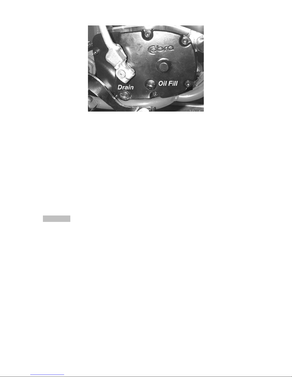
Figure 1
4. After it has drained, reinstall the plug, being sure that the gasket is in place.
5. Reapply oil from oil fill plug 235 cc (8.0 oz) Cobra Venom 3 Shoe Clutch Milk
thru the oil fill plug.
NOTE:
Putting additional oil, up to 12 oz (295 cc), can help clutch life. More than 12 oz
(295 cc) will degrade engine performance.
NOTE:
Lean bike over onto it’s left hand side so that the clutch cover is up unless you
have a squeeze bottle.
6. Reapply the oil fill plug, hand tight, being sure the gasket is in place.
CAUTION:
Cobra has spent considerable time and money developing the proper lubrication
to handle the harsh environment of the automatic clutch and transmission of this
motorcycle. Cobra’s specially developed Cobra Venom 3 Shoe Clutch Milk
(Part
# MCMUGF01) was formulated to provide superior lubrication and cooling
capability over extended periods of time and is the recommended lubricant for
your Cobra motorcycle.
13
Page 15
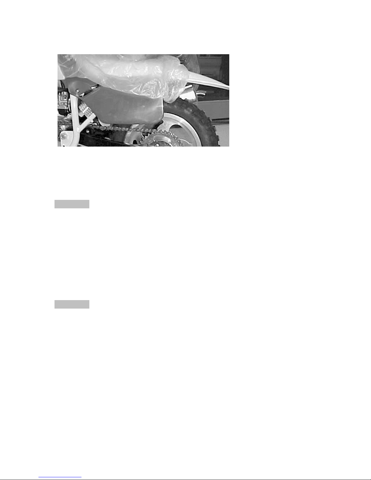
Proper Chain Adjustment
1. Make sure that the rear
wheel is aligned properly.
Push down on the seat,
2.
compressing the suspension down to where the
chain is tightest. At this
point, there should be a
minimum of 1” of slack.
With the rear wheel
3.
Figure 2
elevated, there should be
a minimum of 2.5” of
slack between the swing
arm and the chain.
Rear Brake Maintenance
CAUTION:
Too little brake pedal free-play will allow the brake pads to drag causing the pads
to wear prematurely and possible engine component failures. Too much free-play
will not allow the rider to apply the brakes quickly.
1. Set pedal height/position first, then
2. Set pedal free play.
Brake pedal height can be adjusted with the bolt and nut located under the rear
of the brake pedal. The free-play is adjusted with the adjustable plunger on the
end of the brake pedal.
CAUTION:
Use only DOT 4 brake fluid
Setting rear brake pedal position (see figure 2b):
1. Loosen the lock nut (10mm wrench).
2. Adjust the brake lever stop (10mm wrench) so that the lever is comfortably
reachable in both:
a. Standing riding position, and
b. Sitting riding position.
3. Tighten the lock nut (10 mm wrench).
14
Page 16
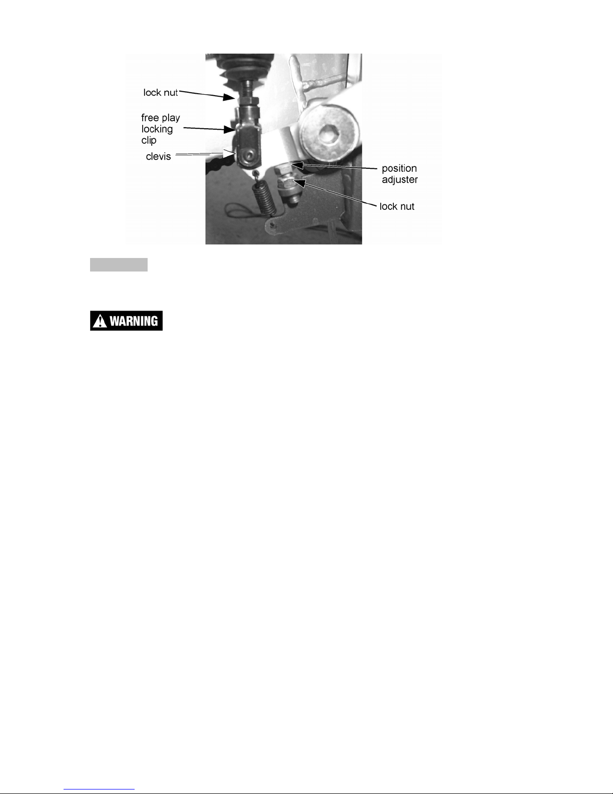
Figure 2b
CAUTION:
Adequate pedal free play is required so that the brake pads do not drag on the
rotor. 1” MINIMUM.
Make sure that the free play locking clip is installed such that one must push
forward, toward the front of the bike, to remove. Otherwise the clip is apt to come
undone while riding.
To adjust (see figure 2b):
1. Loosen the lock nut (10mm).
2. Undo the free play locking clip from around the brake adjustor (plunger),
with your hand by pushing it forward.
3. Slide the pin of the locking free play locking clip from the brake lever
4. Adjust as needed by rotating the clevis on the end of the adjustor
(plunger).
NOTE:
Turning the clevis Clockwise will lengthen the adjustor (plunger), removing free
play from the system, and turning the clevis Counter-Clockwise will shorten the
adjustor (plunger) adding free play to the system.
15
Page 17
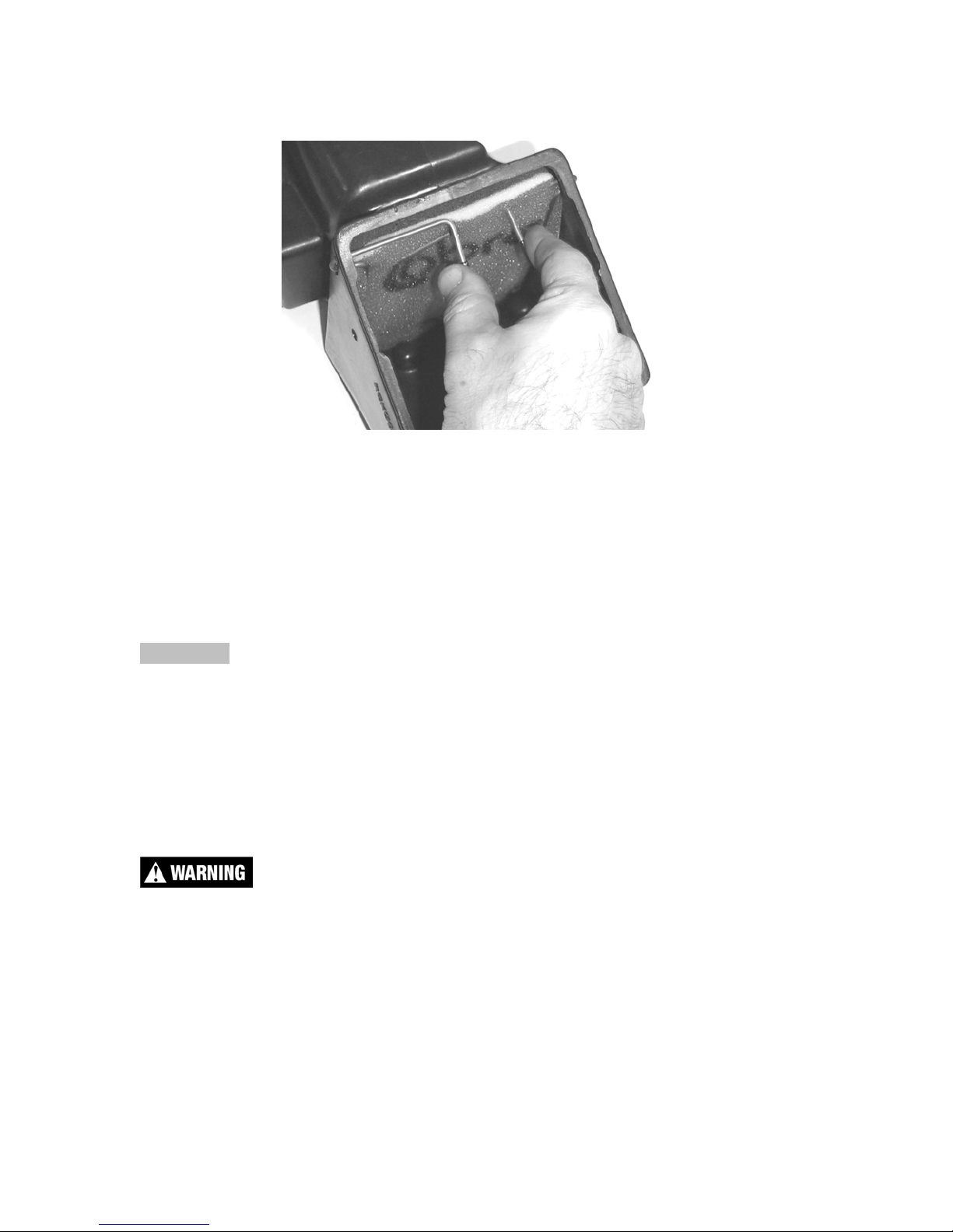
Air Filter Cleaning
Figure A1
• Remove the seat (unscrew the knob under the seat & rear fender)
• Squeeze the two tabs together as shown in figure A1 and pull the wire
retainer up and out of the air box
• The filter may now be pulled from the airbox
• Clean the airbox of dirt and clean the filter sealing surface of the old sealing
grease.
CAUTION:
Pay particular attention to clean any particles from the airbox between the filter
location and the carburetor.
NOTE:
Cobra has available a carburetor cover that allows easy cleaning of the airbox.
1. Remove the air boot
2. Install the cover (RCMU0109) over the carburetor inlet
3. Spray out the airbox.
Do not clean the air filter with gasoline or other highly volatile petroleum product.
Diesel fuel or kerosene would be preferred but caution should still be taken. Hot
soapy water works well.
1. Clean the filter in hot soapy water to remove all dirt particles.
2. Allow it to dry thoroughly.
3. Saturate with filter oil and remove excess.
16
Page 18
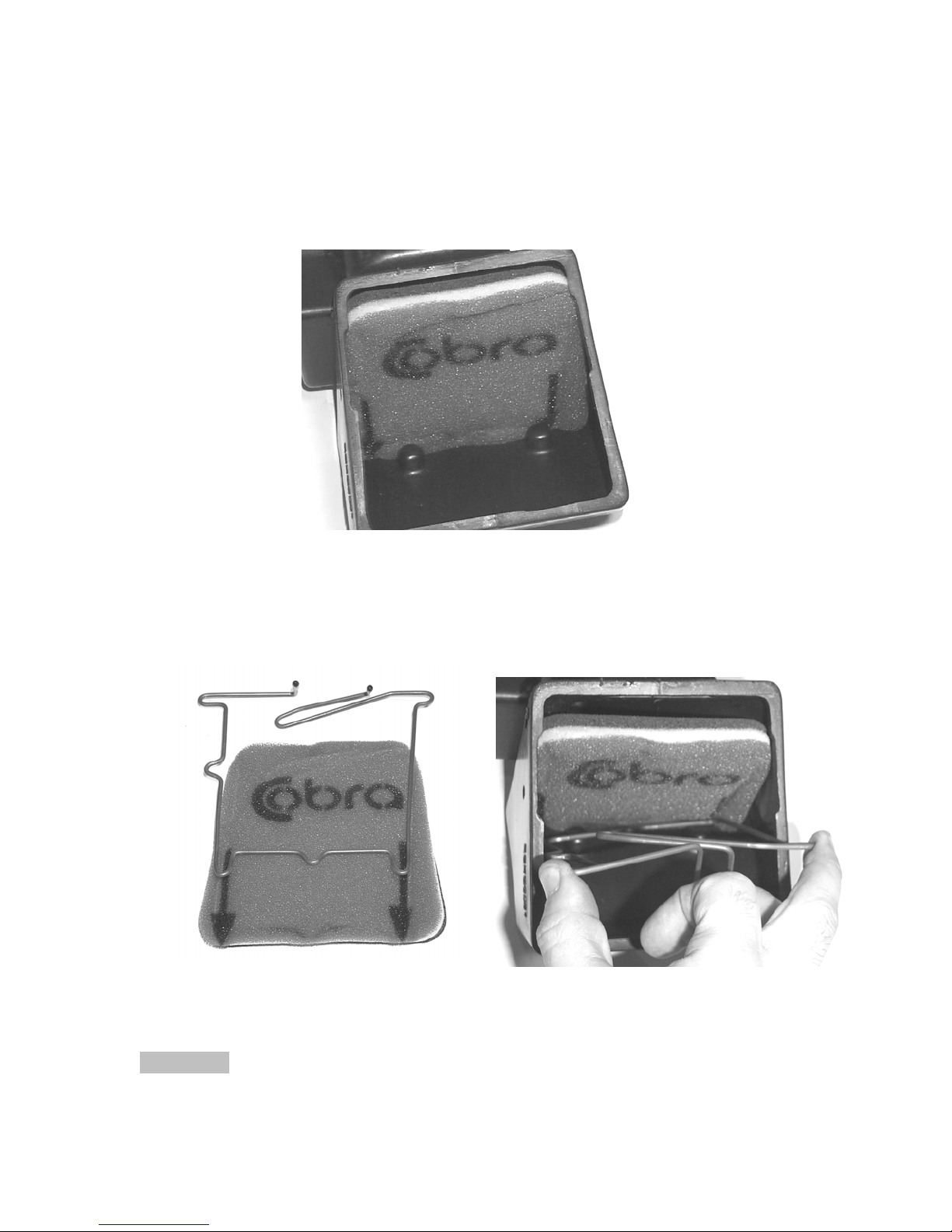
NOTE:
It’s very important to oil your filter consistently each time because varied amounts
of oil will change your carburetor jetting.
4. Apply grease to the black sealing surface of the filter and reinstall as in figure
A2.
Figure A2
5. Squeeze the two finger tabs together on the wire retainer and install into the
airbox while aligning the bottom guiding tabs “legs” with the arrows on the
filter (figures A3 & A4)
Figure A3 Figure A4
6. Push the wire retainer down until it bottoms
CAUTION:
If the side arms do not align with the associated holes it is quite likely that the
legs did not make it into the holes. Realign and try again.
17
Page 19
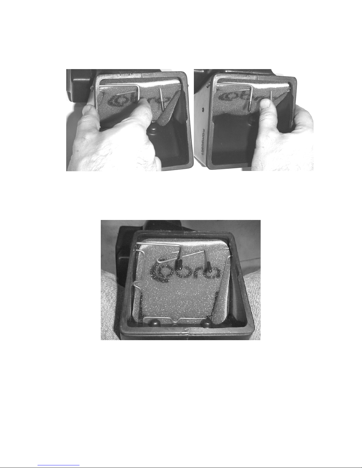
7. Press each side arm into their respective holes one at a time with each finger
tab.
Figure A5 Figure A6
8. When properly installed, the filter and retainer should look like figure A7, with
the filter material extending beyond the perimeter of the wire retainer
NOTE:
Make sure you change or clean your filter after each moto. We recommend
carrying multiple filters in your toolbox, one for each practice session and moto.
Figure A7
18
Page 20

Fork Oil Replacement
Tools required
• Two 19 mm wrenches or sockets
• 4 & 5 mm hex key (Allen wrench)
• 25mm wrench or socket
• 5 wt fork oil
Disassembly procedure
1. Remove the front wheel (19 mm wrench).
2. Remove the brake caliber from the fork leg (4 mm hex key).
3. Loosen the fork caps (25mm socket).
4. Remove the fork legs from the triple clamps (5 mm hex key).
5. One leg at a time
a. Remove the fork cap from the leg.
b. Separate the fork cap from the damper rod.
c. Pull out the fork spring.
d. Place upside down over a suitable pan, tray, or container.
e. Work the damper rod up and down several times.
f. Allow it to drain completely.
Assembly procedure
1. Fill the fork leg with 4.4 oz (130 ml) 5 wt fork oil.
2. Measure the fork oil level to the top of the fork tube with the leg collapsed,
and record for tuning purposes.
3. Install the fork spring.
4. Reconnect the damper rod to the fork cap (12 ft-lb, 16 Nm).
CAUTION:
The damper rod is hollow and will break if the nut is over tightened.
5. Reinstall the for cap into the fork leg (5 ft-lb, 6.7 Nm)
6. Reinstall the fork legs into the clamps (6 ft-lb, 8 Nm).
7. Reinstall the brake caliper.
8. Reinstall the front wheel (25 ft-lb, 34 Nm).
19
Page 21

Frictional Drive (CFD)
The Cobra Frictional Drive (CFD) is essentially a slip clutch that dissipates torque
spikes transmitted from the rear wheel to the rest of the drive line and engine.
Instead of these torque spikes potentially damaging internal components, the
CFD allows the transmission to slip with respect to the engine. For this to occur,
the CFD must function properly by ‘slipping’ between a minimum torque value,
and a maximum torque value.
The slip torque of the CFD should be checked every 5 hours of operation.
Slip Torque
Minimum 50 67
Maximum 125 169
With the clutch cover off, you can check the slip torque by ‘blocking’ the primary
gear with a suitably strong device, or Cobra tool EAMU0004, and then rotate the
blue CFD nut counter clock-wise with a torque wrench observing the reading
when the nut (and shaft) turn.
If you do not have the capability of checking for proper slip torque, you should
replace the friction papers and the load spring (Bellville spring) every 10 hours to
ensure proper operation.
NOTE
To loosen and tighten the blue CFD nut, use a strong wooden object (large
hammer handle) through the spokes of the rear wheel as a brace against the
swingarm to stop transmission shaft rotation.
CAUTION:
The blue CFD nut has left hand threads which require clock-wise rotation to
loosen.
Ft-lb N-m
20
Page 22
Parts
Parts – Airbox & Inlet System
Figure 5
Coolant System
REF # PART # DESCRIPTION
1 RCKG0501 AIRBOX
2 HCBF0616 M6X16 FLANGE HEAD BOLT
3 RCKG0512 AIR FILTER
4 RCKG0503 FILTER RETAINER
5 TCKG0004 MUDFLAP – AIRBOX
6 TCKG0105 BRACKET – MUDFLAP
7 HCBB0612 M6X12 BUTTON HEAD BOLT
8 MCKGHO03 HOSE CLAMP – AIRBOX TO BOOT
9 RCKG0505 AIR BOOT
10 MCKGHO01 HOSE CLAMP – BOOT TO CARB
11 MCKGHO04 HOSE CLAMP – CARB TO MANIFOLD
12 ECKG0203 INLET MANIFOLD
14 ECKG0202 REED CAGE ASSEMBLY WITH REEDS
NOT SHOWN
15 ZCMU0132 GASKET – REEDS TO ENGINE
16 HCBC0625 M6X25 SOCKET HEAD CAP SCREW
17 HCWF0601 6MM FLAT WASHER
NOT SHOWN
ECKG0205 REED REPLACEMENT KIT
RCCM1301 VELOCITY STACK
21
Page 23
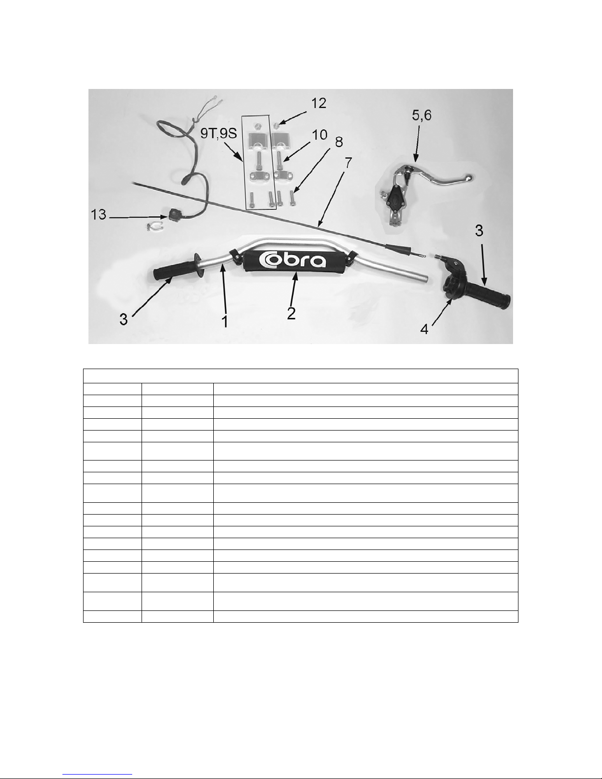
Parts – Bars and Controls
Figure 3
Bars and Controls
REF # PART # DESCRIPTION
1 TCMU0402 HANDLEBAR - ALUMINUM
2 MCMU0001 OPTIONAL CROSS BAR PAD
3 TCMU0008 GRIPS (SET OF TWO)
4 FCMU0066 THROTTLE ASSEMBLY
NOT
SHOWN
5 BCKG0023 ALLOY BRAKE LEVER W/BALL
6 BCKG0024 BRAKE PERCH ASSY W/LEVER & BALL
NOT
SHOWN
7 FCMU0019 THROTTLE CABLE
8 HCBC0806 SOCKET HEAD CAP SCREW M8 X 30 (4 PER)
9S TKMU0404M BAR MOUNT KIT, SHORT (2 PER)
9T TKMU0403M BAR MOUNT KIT, TALL (2 PER)
10 HCBC1001 M10X45 SOCKET HEAD CAP SCREW (2 REQ’D PER BIKE)
12 HCNL1001 M10 LOCK NUT
NOT
SHOWN
NOT
SHOWN
13 FCMU0033 KILL SWITCH ASSEMBLY
FCMU0068 THROTTLE COVER
BAKG0004 SHIELDED BRAKE HOSE ASSEMBLY
HCBH0816 M8 X 16 HEX HEAD BOLT
HCWF0801 8MM FLAT WASHER
22
Page 24
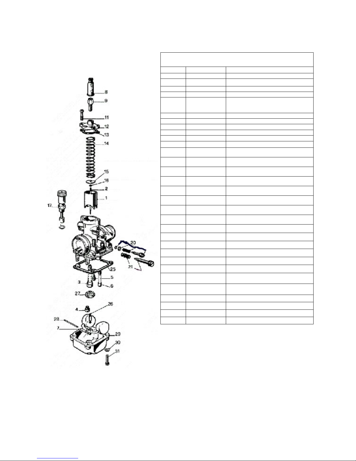
Parts - Carburetor
Figure 4
Carburetor
REF. # PART # DESCRIPTION
1 RCMU0305 CARB SLIDE
2 RCMU0601 NEEDLE
3 RCMU00 ATOMIZER 2.62 AU
4 RCMU00xx MAIN JET, xx denotes size
5 RCMU00xx PILOT JET, xx denotes size
6 CHOKE JET
7 RCMU0301 FLOAT
8 RCMU0102 RUBBER CABLE CAP SEAL
9 RCMU0003 CABLE ADJUSTOR
11 RCMU0006 TOP CARB SCREW
12 RCMU0106 CARB TOP
13 ZCMU0007 TOP CARB GASKET
14 RCMU0004 SLIDE SPRING
15 RCMU0028 NEEDLE RETAINER PLATE
16 RCMU0007 NEEDLE CLIP
17 RCMU0204 CHOKE ASS’Y. 2001 CM
20 RCMU0009 FUEL MIXTURE SCREW
21 RCMU0011 IDLE ADJUSTMENT SCREW
25 RCMU0103 FLOAT BOWL GASKET
26 RCMU0107 FLOAT NEEDLE
27 RCMU0012 DIFFUSER
28 RCMU0016 FLOAT RETAINER PIN
29 RCMU0108 FLOAT BOWL
30 HCWF0401 WASHER 4MM FLAT
31 RCMU0201 SCREW – FLOAT BOWL
NOT
SHOWN
NOT
SHOWN
Not Shown FCMU0026 FUEL LINE, 5”
Not Shown MCMUCL04 HOSE CLAMPS – FUEL LINE
Not Shown RCMU0018 CARBURETOR COMPLETE 19 mm
Not Shown RCMU0022 VENT HOSE 2” EACH
RCCM1301 VELOCITY STACK -05
MCKGHO01 CLAMP – CARBURETOR TO FILTER
23
Page 25

Parts – Coolant System
Figure 5
Coolant System
REF # PART # DESCRIPTION
1 FCKG0036 RADIATOR WITH CAP
2 FCMU0047 RADIATOR CAP (2 ears or ribbed)
3 MCMUHO05 RADIATOR HOSE, TOP, LEFT
4 MCKGHO02 RADIATOR HOSE, BOTTOM, RIGHT
5 MCMUGR03 MOUNTING GROMMET (3 PER)
6 FCMU0006 RADIATOR MOUNTING BRACKET (TEARDROP)
7 HCBF0616 FLANGE HEAD BOLT M6X16
8 MCMUCL07 HOSE CLAMP (4 REQ’D)
9 FCKG0214 RADIATOR OVERFLOW HOSE, 22”
Not Shown
Not Shown
Not Shown
Not Shown
MCMUCL05 HOSE CLAMP FOR OVERFLOW HOSE
FCKG0001 LOUVER
HCSP0002 PUSHPIN (2 REQ’D)
HCCN0000 5 MM CLIP NUT
24
Page 26
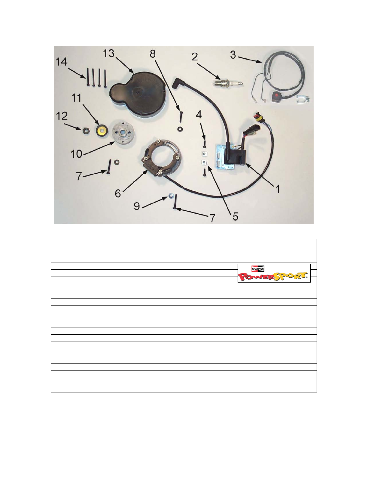
Parts – Electrical System
Figure 6
Electrical System
REF # PART # DESCRIPTION
1 IAMU0005 COIL W/SPARK PLUG CAP
2 ECMU0065 SPARK PLUG, CHAMPION (8339-1)
2H ECMU0067 OPTIONAL HOTTER PLUG (8332-1)
2C ECMU0066 OPTIONAL COLDER PLUG (8904-1)
3 FCMU0033 KILL SWITCH ASSEMBLY
4 HCBC0516 SCREW, M5 X 16 (2 PER)
5 HCCN0000 5MM CLIP NUT (2 PER)
6 ICMU0018 STATOR WITH GROMMET
7 HCBC0535 5mm x 35 SOCKET HEAD CAP SCREW (2 REQ’D)
8 HCBC0525 5mm x 25 SOCKET HEAD CAP SCREW
9 HCWF0504 WASHER FOR STATOR (3 PER)
10 ICMU0006 ROTOR
NOT SHOWN
11 ECKG0042 PULLEY, WATERPUMP CRANK
12 HCNS1001 NUT 10MM
13 ECKG0001 IGNITION COVER
14 HCBC0445 M4 X 45 SOCKET HEAD CAP SCREW (4 REQ’D)
NOT SHOWN
ICMU0012 WOODRUFF KEY
ZCKG0101 GASKET – IGNITION COVER
25
Page 27

Parts – Engine – Bottom End and
Transmission
Figure 7A
Engine Bottom End and Transmission
REF # PART # DESCRIPTION
1 EKMU0023 ENGINE CASE SET W/B&S 50 07
2 EKMU0023 ENGINE CASE SET W/B&S 50 07
3 ZCMU0601 GASKET, CRANKCASE CENTER
4 HCBC0605 6X40MM SOCKET HEAD CAP SCREW (6 REQ’D)
5 HCBC0608 6X55MM SOCKET HEAD CAP SCREW (1 REQ’D)
6 HCBC0606 6X45MM SOCKET HEAD CAP SCREW (2 REQ’D)
7 ECMU0038 CRANKSHAFT
8 ECMU0016 BEARING, CRANKSHAFT
9 ECMU0118 SEAL, CRANKSHAFT
10 ECDC0031 DOWEL, ENGINE CASE ALIGNEMENT (2 REQ’D)
11 ECMU0099 OUTPUT SHAFT, TRANSMISSION WITH GEAR
12 ECMU0100 SECONDARY SHAFT, TRANSMISSION WITH GEAR
13 ECMU0001 BEARING, TRANMISSION SECONDARY SHAFT
14 ECKG0031 BEARING OUTPUT SHAFT, RIGHT SIDE
15 HCBH0612 M6X12 HEX HEAD SCREW - BEARING RETAINER (2 PLACES)
16 HCWL0601 6MM LOCK WASHER
17 ECMU0020L BEARING, TRANSMISSION PRECISION
18 ECKGBR01 BEARING, TRANSMISSION OUTPUT SHAFT
19 ZCDCOR01 O-RING, SPROCKET SPACER
20 ECMU0072 SEAL, OUTPUT SHAFT
21 ECMU0073 SPACER, SPROCKET
22 ECKGSR03 SNAP RING, SPROCKET
NOT SHOWN
23 HCBH0805 M8X12 SCREW – COOLANT DRAIN
24 HCWC0000 COPPER GASKET
25 ECMU0533 FITTING, CRANKCASE VENT
26 RCMU0021 VENT HOSE, CRANKCASE, 9”
27 HCWF0316 WASHER – FLAT
28 ECMU0156 SHIM – OUTPUT SHAFT 50’S
PCKG0014 SPROCKET, 14 T
26
Page 28

Parts –
Engine
Clutch
and
Kicker
Figure 7B
Engine – Clutch and Kick Starter
REF # PART # DESCRIPTION
1 CAMU0005 CLUTCH COMPLETE
2 CAMU0013 CLUTCH SHOES (SET OF 3) WITH BOLT & WASHERS
3 CCMU0029 CLUTCH ARBOR
4 CAMU0010 SPRINGS, WASHER & BOLT (SET OF 3)
5 HCBS0004 CLUTCH BOLT (3 REQ’D)
6 ECMU0018 CLUTCH NUT, SPECIAL
7 ECMU00120 CLUTCH BASKET WITH NEEDLE BEARING
8 ECMU0119 CLUTCH BEARING
9 ECMU0040 CLUTCH TO HUB SPACER (0.030”, 0.76MM)
ECMU0040T CLUTCH TO HUB SPACER (THIN – 0.015”, 0.38MM)
10 ECMU0132 COOLANT FITTING
11 ECMU0141 HUB, CFD
12 ECMU0142 PLATE, CFD (2 REQ’D)
13 ECMU0143 PAPER, CFD (2 REQ’D)
14 ECMU0144 GEAR, CFD
15 ECMU0145 SPRING WASHER, CFD
16 HCWF0002 WASHER FLAT, CFD (13MM)
17 HCNS1202 NUT, CFD (½-20 LEFT HAND THREAD – BLUE)
18 EAMU0001 KICKSTART GEAR & SHAFT
19 ECMU0116 SPRING, KICKSTART
20 ZCMUB014 O-RING KICK SHAFT
21 HCWS1622 SHIM, KICK SHAFT
22 ECDC0036 SNAP RING, KICK SHAFT
23 ECDC0046 KICK LEVER W/BOLT
24 HCBF0620 6MM X 20 FLANGE HEAD BOLT
25 ECMU0115 CLUTCH COVER
26 ZCMU0030 CLUTCH COVER GASKET
27 ECMU0037 OIL FILL PLUG
28 ZCMU0005 GASKET, OIL FILL / DRAIN PLUG
29 HCBF0655 6MM X 55 FLANGE HEAD (6 REQ’D)
30 ECMU0207 KICKSTART GEAR SMALL
31 ECMUSP01 KICK START DOG SPRING (PAPER CLIP)
32 HCWS0802 WASHER – KICK GEAR SPACING
33 ECMU0134 SHIM - CFD
27
Page 29

Parts – Engine – Ignition and Water Pump
Figure 7C
Engine – Ignition and Water Pump
REF # PART # DESCRIPTION
1 EKMU0001 WATER PUMP KIT
2 ECKG0142 SHAFT, WATER PUMP
3 ECKG0072 BEARING, WATER PUMP
4 ECKG0074 SEAL, WATER PUMP SHAFT
5 ECKG0073 IMPELLER, WATER PUMP
6 ECKG0004 RETAINER, WATER PUMP ASSEMBLY
7 HCBB0003 5MM X 12 BUTTON HEAD STAINLESS
8 HCWF0501 FLAT WASHER
9 ECKG0175 WATER PUMP PULLEY, FAN TYPE - DRIVEN
10 ECMU0180 BELT RETAINER
11 HCBS0003 SHOULDER BOLT 6MM
12 ECKG0170 WATER PUMP BELT
13 ECKG0042 WATER PUMP PULLEY, CRANK
14 HCNS1001 NUT 10MM
15 HCBC0408 M4mm x 8 SOCKET HEAD black oxide
16 HCWF0401 4MM WASHER
28
Page 30
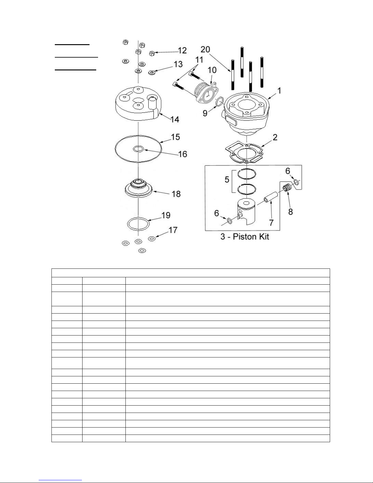
Parts –
Engine –
Top End
Figure 7D
Engine – Top End
REF # PART # DESCRIPTION
1 ECMU0052 CYLINDER
BASE GASKET 0.015” (0.4mm thick) For other Base Gaskets refer to
2 ZCKG0501
3 ECMU0060 PISTON KIT
5 ECMU0155 PISTON RINGS (2 PER SET)
6 ECMUSR00 SNAP RING FOR PISTON (2 REQ'D)
7 ECKG0012 WRIST PIN
8 ECMU0077 BEARING, WRIST PIN
9 ZCMUOR07 O-RING, EXHAUST FLANGE
10 ECMU0086 EXHAUST FLANGE
NOT
SHOWN
ZCMOTE11 O-RINGS – PIPE TO FLANGE (2 REQ’D)
11 HCBC0612 M6X12, EXHAUST FLANGE SCREW (2 REQ'D)
12 HCNS0601 6mm Nut
13 HCWS1401 HARDENED WASHER
14 ECMU0530 CYLINDER HEAD OUTER
15 ZCMUOR02 O-RING, CYLINDER HEAD LARGE
16 ZCMUV024 O-RING CYLINDER HEAD SMALL
17 ZCMUOR10 O-RING CYLINDER STUD (4 REQ'D)
18 ECMU0532 CYLINDER HEAD, INSERT
19 ZCMUV032 O-RING CYLINDER HEAD MEDIUM
20 ECMU0075 STUD, CYLINDER 6mm
Base Gasket Selection section of this manual
29
Page 31

Parts – Exhaust System
Figure 8
Exhaust System
REF # PART # DESCRIPTION
1 XCKG2007 2007 CX50 SR EXHAUST PIPE
2 ZCMOTE11 HEADER PIPE O-RINGS (2 REQ’D)
3 XCMU0005 EXHAUST SPRING - SHORT
4 MCMUGR06 PIPE GROMMET MALE
5 MCMUGR07 PIPE GROMMET FEMALE
6 MCMUSP02 PIPE GROMMET SPACER
7 HCWF1478 PIPE GROMMET WASHER (2 REQ’D)
NOT SHOWN
8 HCBF0635 M6X35 FLANGE HEAD BOLT
NOT SHOWN
9 XCMU0032 SILENCER
NOT SHOWN
NOT SHOWN
10 XCKG0009 PIPE / SILENCER SEAL
11 MCMUGR03 MOUNTING GROMMET (4 REQ’D TOTAL, 2 PER BOLT)
12 TCKG0001 SPACER (2 REQ’D)
13 HCBF0630 M6X30 FLANGE HEAD BOLT (2 REQ’D)
NOT SHOWN
14 FCKG0028 BRACKET – RIGHT SIDE RADIATOR SHROUD
NOT SHOWN
NOT SHOWN
MCMUGR02 GROMMET KIT
HCHA0003 6MM CLIP NUT – FOR FRONT PIPE MOUNT
XCMU0026 SILENCER PACKING KIT
HCBB0408 M4 X 8 SILENCER SCREW
HCNF0601 6MM FLANGE NUT (2 REQ’D) – SILENCER MOUNTING NUT
HCHA0003 6MM CLIP NUT FOR PIPE MOUNTING
HCCN0000 5MM CLIP NUT (ON SHROUD BRACKET)
30
Page 32

Parts – Forks & Triple Clamps
Figure 12
Front Forks and Triple Clamp
REF # PART # DESCRIPTION
1 KAKG0020 FORK COMPLETE, NON-BRAKE SIDE
2 KAKG0021 FORK COMPLETE, BRAKE SIDE
3 KCKG0140 FORK GUARD SET
4 KCKG0140 FORK GUARD SET
5 MCMUZT04 CABLE TIE (2 REQ’D)
6 HCBB0612 M6X12, BUTTON HEAD SCREW (4 REQ’D)
7 FAKG0010 TRIPLE CLAMP BOTTOM ASSY, (1 BEARING AND DUST COVER)
8 FCKG0033 TRIPLE CLAMP UPPER
9 HCNJ0102 STEERING HEAD JAM NUT (2 REQ’D)
10 HCBC0625 SOCKET HEAD CS M6X25 (4 REQ’D)
11 HCBC0806 CAP SCREW M8X30 (4 REQ’D)
12S TCMU0404 BAR MOUNT KIT, SHORT (2 REQ’D)
12T TCMU0403 BAR MOUNT KIT, TALL (2 REQ’D)
14 HCBC1001 M10X45 SOCKET HEAD CAP SCREW (2 REQ’D PER BIKE)
15 HCNL1001 M10 LOCK NUT
NOT
SHOWN
NOT
SHOWN
16 FCMU1103 DUST COVER (2 REQ’D)
17 FCMU0004 STEERING HEAD BEARING (2 REQ’D)
NOT
SHOWN
18 HCBC0625 SOCKET HEAD CS M6X25 (4 REQ’D)
19 HCBF0616 FENDER BOLT, M6X16 FLANGE HEAD (4 REQ’D)
20 FCKG0213 BRAKE LINE HOLDER
21 HCBF0620 M6X20 FLANGE HEAD BOLT (NUMBER PLATE FASTNR)
HCBH0816 M8 X 16 HEX HEAD BOLT
HCWF0801 8MM FLAT WASHER
FCMU0011 STEERING HEAD RACE (2 IN STEERING HEAD)
31
Page 33
Parts – Forks – Leg Assembly
Figure 13
Fork Leg Assembly
REF # PART # DESCRIPTION
1 HCBC0408 M4 X 8 SHCS (BLEED SCREW)
2 ZCKG0001 GASKET BLEED SCREW
3
4
5 KCKG0051 BUSHING FORK LEG
6 KCMU0007 FORK SEAL
7 KCKG0052 WIRE FORK ASSY RETAINING
8 KCKG0008 DUST COVER
9 KCKG0048 RUBBER CUSHION
10 KCKG1206 FORK SPRING
11 HCNJ0038 NUT – DAMPER ROD
12 KAKG0001 DAMPER ROD ASSEMBLY
13 KAKG0027 MID VALVE ASSEMBLY (STANDARD)
14 KCKG0022 CARTRIDGE CAP
15 KCKG0054 DAMPER TUBE (CARTRIDGE) 5-star
16 KAKG0024 BASE VALVE ASSEMBLY (STANDARD)
17 KCKG0018 BOTTOM PLUG
18 KCKG0049 GLIDE RING
19,20 KAKG0144 FORK LEG INNER / BOTTOM BRAKE SIDE (not sold separately)
19,21 KAKG0145 FORK LEG INNER / BOTTOM NON-BRAKE SIDE (not sold separately)
22 ZCMUOR08 O-RING GASKET FORKCAP
23 ZCKGB017 O-RING BOTTOM PLUG
24 KCDC0005 O-RING BASE VALVE
25 KCDCSL01 SEAL BAND MID VALVE
KCKG0047 FORK CAP
KCKG0121 FORK LEG OUTER
KAKG0026 MID VALVE ASSEMBLY (LIGHT)
KAKG0032 MID VALVE ASSEMBLY (HEAVY)
KAKG0023 BASE VALVE ASSEMBLY (LIGHT)
KAKG0031 BASE VALVE ASSEMBLY (HEAVY)
32
Page 34

Parts – Frame I
Figure 9
Frame
REF # PART # DESCRIPTION
1 FAKG2007 FRAME 2007 CX50 SR
2 HCBF0616 M6X16 FLANGE HEAD BOLT
3 HCHA0003 6MM “U” NUT
4 TCKG0007 PLUG – FRAME END
5 MCMU0003 STRAP – HANDLE
6 HCBF0620 M6X20 FLANGE HEAD BOLT
7 HCHA0003 6MM “U” NUT
8 HCBF0630 M6X30 FLANGE HEAD BOLT
9 MCMUGR03 GROMMET (2 REQ’D PER BOLT)
10 TCKG0001 ALUMINUM SPACER
11 HCWF1478 PIPE GROMMET WASHER
12 HCBH0880 FRONT ENGINE MOUNT BOLT, M8X30 SHCS
13 HCNL0801 8MM LOCKNUT
14 HCBH1403 SWINGARM PIVOT BOLT
15 HCNL1402 SWINGARM LOCK NUT (M14 X1)
16 MCMUGR03 GROMMET
17 HCBF0616 M6X16 FLANGE HEAD BOLT
18 FCMU0006 RADIATOR MOUNTING BRACKET (TEARDROP)
19 HCHA0003 6MM “U” NUT
20 FCMU0057 CHAIN ROLLER
21 HCWF1201 WASHER FLAT, CHAIN ROLLER (2 REQ’D)
22 HCCP0002 COTTERPIN 3/32 X 1 (2 REQ’D)
33
Page 35

Parts – Frame II
Figure 10
Frame
REF # PART # DESCRIPTION
1 FAKG0011 FRAME 2005 CX50 SR
2 HCBF0616 M6X16 FLANGE HEAD BOLT
3 HCNK0001 KNOB – SEAT FASTENING
4 HCBB0516 M5X16 BUTTON HEAD BOLT
5 HCWP0002 ALUMINUM WASHER
6 HCBB0516 M5X16 BUTTON HEAD BOLT
7 HCCN0000 5 MM CLIPNUT
8 HCBF0620 M6X20 FLANGE HEAD BOLT
9 BCDC0009 BRAKE PIVOT BOLT
10 BCBH0602 M6 X 20 HEX HEAD BOLT
11 HCNS0601 6MM NUT
12 TCMU0010 WIDE FOOTPEGS (PAIR)
13 TCMU0106 FOOTPEG SPRING (SINGLE PIECE)
14 HCBH0840 M8 X 40MM FOOTPEG BOLT
15 HCWF0801 8MM FLAT WASHER
16 HCNL0801 8MM LOCKNUT
17 HCBF0630 FLANGE HEAD BOLT, M6X30
18 MCMUGR06 PIPE GROMMET MALE
19 MCMUGR07 PIPE GROMMET FEMALE
20 MCMUSP02 PIPE GROMMET SPACER
21 FCKG0028 BRACKET – RIGHT SIDE RAD SHROUD
22 HCHA0003 6MM “U” NUT
23 HCBH0502 M5X16 HEX HEAD BOLT
24 HCCN0000 5 MM CLIPNUT
25 HCWF0601 6MM FLAT WASHER (ONLY 1 USED)
34
Page 36

Parts – Front Brakes
Figure 18
Front Brakes
REF# PART # DESCRIPTION
1 BAKG0003 FRONT BRAKE ASSEMBLY
2 BCKG0030 HOSE – BRAKE FRONT
3 BCKG0023 ALLOY BRAKE LEVER
4 BCKG0024 BRAKE PERCH & MASTER CYLINDER ASSY W/ LEVER
5 BCKG0029 CALIPER – FRONT
6 BKKG0001 BRAKE PADS, WITH “E” CLIP
BCKG0009 BRAKE PADS ONLY
7 BCMU0503 BRAKE ROTOR
8 HCBC2512 M5X12 SHCS WITH THREAD LOC (6 REQ’D)
9 FCKG0213 GUIDE – FRONT BRAKE LINE
10 HCBF0635 M6 X 35 FLANGE HEAD BOLT updated these for new fork bottoms
11 HCBF0616 M6 X 16 FLANGE HEAD BOLT
12 WCMUZT04 CABLE TIES (2 REQ’D) TO SECURE BRAKE LINE TO FORK GUARD
13 BCKG0031 BLEED KIT (MULTIPLE SYRINGES, FITTINGS & HOSE)
14 BRAKE FLUID
ACCESSORY
ACCESSORY
ACCESSORY
ACCESSORY
ACCESSORY
ACCESSORY
ACCESSORY
BCKG0028 LEVER ADJUSTMENT KIT
BCKG0027 RESERVOIR SEAL KIT
BCKG0025 REPLACEMENT BAR CLAMP AND SCREWS (FOR MASTER CYLINDER)
BCKG0026 PISTON & REBUILD KIT FOR MASTER CYLINDER
BCKG0017 CALIPER ORING & BOLTS (F&R)
BCKG0018 CALIPER PISTON KIT (F&R)
BCKG0019 RETURN SPRING (4 FINGER SPRING)
35
Page 37

Parts – Front Wheel
Figure 19
Front Wheel
REF # PART # DESCRIPTION
1 WAKG0022 FRONT WHEEL W BEARINGS
2 WCKG1200 12" FRONT TIRE
3 WCKG1201 12" FRONT TUBE
4 WCKG0011 FRONT AXLE
5 WCMU0123 FRONT WHEEL SPACER, X LARGE
6 WCMU0120 WHEEL BEARING (2 REQD)
7 WCMU0032 WHEEL BEARING SPACER
8 WCMU0101 FRONT WHEEL SPACER, LARGE
10 HCWF1202 FRONT AXLE WASHER
11 HCNS1201 FRONT AXLE NUT (12MM)
12 HCBC2512 BRAKE ROTOR MOUNTING BOLTS (6 REQD)
13 BCMU0503 BRAKE ROTOR
36
Page 38

Parts – Plastic Bodywork & Seat
Figure 20
Plastic and Seat
REF # PART # DESCRIPTION
1 TCMU0016 FRONT FENDER
NOT SHOWN
2 TCMU0005 FRONT NUMBER PLATE
NOT SHOWN
3 TCMU0006 FUEL TANK (NO PETCOCK OR CAP)
NOT SHOWN
4 TCMU1203 RADIATOR SHROUDS (RAD CAP ACCESS)
NOT SHOWN
NOT SHOWN
NOT SHOWN
NOT SHOWN
5 TCMU0113 SIDE NUMBER PLATE SET
NOT SHOWN
NOT SHOWN
6 TAMU0001 REAR FENDER ASSEMBLY
NOT SHOWN
7 TCMU0505 SEAT
8 TCMU0103 FUEL TANK CAP
9 TCMU0000 FUEL PETCOCK (06 LEVER)
10 HCNK0001 KNOB – SEAT FASTENING
11 FCKG0028 BRACKET – RIGHT SIDE RAD SHROUD
NOT SHOWN
NOT SHOWN
NOT SHOWN
12 MCMU0003 STRAP HANDLE
NOT SHOWN
NOT SHOWN
NOT SHOWN
HCBF0616 FRONT FENDER MTG BOLTS (4 REQD)
HCBF0625 FRONT NUMBER PLATE MTG BOLT
HCBF0616 FUEL TANK MOUNTING BOLT
HCBB0402 RAD SHROUD TO TANK BOLT, LONG (1 PER SIDE)
HCBB0403 RAD SHROUD TO TANK BOLT, SHORT (1 PER SIDE)
HCBB0516 M5X16 RAD SHROUD MOUNT BOLT (1 PER SIDE)
HCWP0002 SHROUD WASHER (1 PER SIDE)
HCBB0516 M5X16 NUMBER PLATE MTG SCREW (2 PER SIDE)
HCWP0002 NUMBER PLATE WASHER (UPPER HOLE ONLY)
HCBH0620 REAR FENDER MTG BOLT (2 REQD)
HCCN0000 5MM CLIP NUT
HCBB0516 M5X16 RAD SHROUD MOUNT BOLT (1 PER SIDE)
TCKG2007 GRAPHIC KIT – CX50 SR 2006
FCKG0001 LOUVER
HCCN0000 5MM CLIPNUT
HKPP0001 PUSH PINS – 10 PACK SHROUD FASTENING
37
Page 39

Parts – Rear Brake
Figure 21
Rear Brake System
REF # PART # DESCRIPTION
BAKG0002
1 BCMU0012 BRAKE PEDAL
2 BCDC0009 BRAKE PIVOT BOLT
3 HCBH0620 M6X20 HEX HEAD BOLT
4 HCNS0601 6 MM NUT
5 BCMUSP02 BRAKE RETURN SPRING
6 BCMU0501 SEAL – BRAKE PEDAL (2 REQ’D)
7 BCDC0004 PUSH ROD, REAR BRAKE
8 HCBF0620 M6X20 FLANGE HEAD BOLT (2 REQ’D)
9 HCPP0832 BRAKE HOSE CLAMP FASTENER (2 REQ’D)
10 HCCC0000 BRAKE HOSE CLAMP (2 REQ’D)
11 BCKG0010 REPLACEMENT BRAKE HOSE
12 HCBF0635 M6X35 FLANGE HEAD BOLT
13 HCBF0620 M6X20 FLANGE HEAD BOLT
14 BCKG0013 CALIPER – REAR BRAKE
ACCESSORY
15 BCKG0103 BRAKE CARRIER WITH PAD
16 BCKG0006 WHEEL SPACER - FLOATING CARRIER
17 BCMU0502 BRAKE ROTOR
18 HCBC1616 M6X16 SOCKET HEAD CAP SCREWS (5 REQ’D)
19 BCKG0012
ACCESSORY
ACCESSORY
ACCESSORY
ACCESSORY
ACCESSORY
ACCESSORY
BKKG0001 BRAKE PADS WITH “E” CLIP
BCKG0014 FITTING KIT
BCKG0015 MASTER CYLINDER PISTON / SEAL KIT
BCKG0016 RESERVOIR SEAL KIT
BCKG0017 CALIPER BOLT / O-RING KIT
BCKG0018 CALIPER PISTON / SEAL KIT
BCKG0019 PAD RETURN SPRING (4 LEG SPRING)
BRAKE COMPLETE
MASTER CYLINDER - REAR
38
Page 40

Parts – Rear Wheel
Figure 22
Rear Wheel
REF # PART # DESCRIPTION
1 WAKG2007R REAR WHEEL W/BEARINGS
2 WCMU1275 REAR TIRE, VEE RUBBER 2.75X10
3 WCMUTU10 TUBE, 10"
4 BCMU0502 BRAKE ROTOR
5 HCBC1616 M6X16 SOCKET HEAD CAP SCREWS (5 REQ’D)
6 PCMU0138 38T STEEL REAR SPROCKET (NO DAMPERS)
7 WCMU0020 WHEEL BEARING BRAKE SIDE
9 HCBH0702 M7X30 HEX HEAD BOLT
10 PCMU0100 CHAIN 420 X 100
11 PCMU0001 MASTER LINK 420
12 WCMU0016 REAR AXLE
13 HCPA0002 AXLE HEAD FIXING PLATE
14 BCKG0006 WHEEL SPACER - FLOATING CARRIER
15 BCKG0103 BRAKE CARRIER
NOT
SHOWN
16 WCMU0120 WHEEL BEARING SPROCKET SIDE
17 WCMU0033 WHEEL BEARING SPACER
18 WCMU0101 WHEEL SPACER
19 HCWF1202 AXLE WASHER
20 HCNL1201 AXLE NUT 12MM
BCKG0104 BRAKE CARRIER PAD
39
Page 41

Parts – Shock
Figure 23
Shock
REF # PART # DESCRIPTION
1 HCBF1040 M10 X 40 HEX HEAD BOLT
2 SCKGFX04 PRELOAD RING BOTTOM
3 SCKGFX05 PRELOAD RING TOP (LOCK RING)
4 SCKGFX37 SHOCK SPRING 3.7 KG/MM (STANDARD)
SCKGFX35 SHOCK SPRING 3.5 KG/MM (LIGHT)
SCKGFX39 SHOCK SPRING 3.9 KG/MM (HEAVY)
5 SCKGFX03 SPRING RETAINER BOTTOM
6 SCKGFX01 COLLAR – SHOCK END MOUNT
7 ZCMU0114 O-RING – SHOCK END MOUNT
8 SAKG2006 REAR SHOCK (FOX)
10 SCKGFX06 BEARING – SPHERICAL SHOCK MOUNT
11 SCKGFX07 RETAINING RING SHOCK END BEARING
40
Page 42

Parts – Swingarm Assembly
Figure 24
Swingarm
REF # PART # DESCRIPTION
GAKG2004 SWINGARM ASSEMBLY COMPLETE
1 GAKG0002 SWINGARM PAINTED
2 HCBF1403 SWINGARM PIVOT BOLT
3 HCNL1402 SWINGARM LOCK NUT (M14 X1)
4 GCMU0001 SWINGARM BUSHING (4 PER)
5 GCMU0005 TOP SWINGARM GUARD (CHAIN SLIDER)
6 HCBB0803 M8X40 BUTTON HEAD BOLT
7 HCWF5601 FLAT WASHER
8 HCNL0801 8MM LOCK NUT
9 PAKG0002 CHAIN GUIDE ASSEMBLY COMPLETE
10 HCBF1401 1/4 X 20 X 1-1/2" FLAT HEAD SCREW (2 PER)
11 HCNL1401 1/4" LOCKNUT (2 PER)
12 HCBF0620 M6 X 20 FLANGE HEAD BOLT (2 PER)
13 HCCC0000 BRAKE HOSE CLAMP (2 PER)
14 HCPP0832 BRAKE HOSE CLAMP FASTNER (2 PER)
15 HCBF1040 M10 X 40 LOWER SHOCK MOUNT BOLT
16 FCMU0203 WHEEL PULL
17 FKMU0005 WHEEL PULL ENDCAP WITH WASHER
18 HCBH0810 WHEEL PULL BOLT M8X65
19 HCWF801 WHEEL PULL WASHER (M8)
20 WCMU0016 REAR AXLE
21 HCPA0002 AXLE HEAD FIXING PLATE
22 HCNL1201 AXLE NUT, 12 MM
23 HCWF1202 AXLE WASHER
24 GCMU0017 OPTIONAL TOP CHAIN SLIDE
25 HCFH0516 FLAT HEAD SCREW
26 HCWF0501 WASHER
27 HCNL0501 LOCK NUT
28 PCKG0004 BOTTOM CHAIN SLIDER
29 FAMU0005 WHEEL PULL ASSEMBLY COMPLETE
30 GCKG0008 SWINGARM PIVOT TUBE SPACER (2 REQ’D)
41
Page 43

Service
Trained technicians with precision gauging and proper assembly fixtures carefully
assemble all Cobra engines to specific tolerances. If you feel you have the skills,
and the appropriate tools, to perform the following service tasks please follow the
instructions closely. The part numbers are listed throughout to help you when
ordering parts from your local Cobra dealer.
If you don’t feel comfortable with the service work, log on to
www.cobramotorcycle.com to find a Cobra dealer or Call 517 437 9100.
Engine Service
One method for determining whether the top end of your engine needs rebuilt is
to perform a WOT (Wide Open Throttle) kicking compression test. Before
performing the procedure please read the caution notes below.
CAUTION:
• There appears to be a wide range of variability in reading compression
gauges across the country.
• The head volume of this Cobra Motorcycle is very small and so requires many
kicks ~20 before you establish the most accurate reading possible.
• Because of the geometry of the spark plug used in this Cobra Motorcycle, the
adapter used with your compression tester must have a similar volume
protruding into the combustion chamber to establish an accurate value.
• Length of hose on the compression tester will affect the reading. The shorter
the hose length the more accurate your reading will be.
Because of these difficulties in measuring an absolute compression value, a
useful relative value can be achieved by testing your bike’s compression with
your own particular gauge after a new top end or when the bike is new so that
you know what your particular gauge reads on a ‘fresh’ engine. When it has
dropped to 90% of its original value the engine will be down on power and would
benefit from a rebuild. When it’s dropped to 80% it really needs rebuilt! Using the
table below will help you determine monitor the condition of your top end.
Example
Your Values
Engine is Fresh
Measured Value
110 psi 110 psi * 0.9 = 99 psi 110 psi * 0.8 = 88 psi
Engine Down on Power
Measured Value * 0.9
Engine NEEDS Rebuilt
Measured Value * 0.8
42
Page 44

Procedure for Compression Testing
1. Shut off the fuel petcock.
2. Install the compression gauge into the spark plug hole.
3. Hold the throttle to wide open, and kick repeatedly (approximately 20 times)
or until the gauge reading does not increase in value with each kick.
Base Gasket Selection
Tools required
• 17mm wrench
• 1mm flexible solder material
• measurement calipers
When rebuilding the ‘top end’ of your Cobra motorcycle, care must be taken to
ensure the proper squish clearance. Squish clearance is defined as the minimum
distance between cylinder head and piston at TDC, and there are negative
effects of either having too much or too little clearance. Since parts like the crank,
connecting rod, cylinder head, piston, and crankcases all have varying
tolerances, Cobra offers several different base gasket thickness’ to ensure that
you can always set the squish clearance of your engine to factory specifications.
For base gasket replacement use the code (see figure 21 for location) along with
the table on the following page reorder the correct thickness gasket.
Code Supplied Base
Gasket Thickness
# mm inch With silicone bead Without silicone bead
2 0.2 0.008 ZCMU0702
0.25 0.010 ZCMU0011
3 0.3 0.012 ZCMU0703
4 0.4 0.015 ZCKG0501 (new) ZCKG0501 (old)
5 0.5 0.020 ZCMU0705
6 0.6 0.024 ZCMU0706
7 0.7 0.028 ZCMU0707
Figure 21
Cobra #
43
Page 45

8 0.8 0.031 ZCMU0708 ZCMU0012
9 0.9 0.035 ZCMU0709 ZCMU0015
1 1.0 0.039 ZCMU0710 ZCMU0016
NOTE
Tolerances will affect the actual gasket thickness’.
If during the course of the maintenance more parts than the base gasket are
changed, the squish clearance should be measured, and possibly a different
base gasket will be required.
The easiest way to measure squish clearance is with 1mm to 1.5mm thick
flexible solder wire (available through most popular electronic stores). The
process is as follows:
• Assemble the engine without a base gasket to the proper torque
specifications leaving off the spark plug and ignition cover (piston rings can
be left off to ease assembly).
• Carefully insert the solder wire though the spark plug hole, into the cylinder
far enough such that the tip of the wire touches the cylinder wall against one
side or the other (not the front or back as the piston will rock and give
incorrect measurement).
• Hold the wire at this position and turn the crankshaft, by the flywheel nut,
clockwise (counter clockwise can loosen the flywheel nut) one revolution to
‘smush’ the solder wire.
• Pull out the wire and measure the solder thickness, approximately 2mm from
the end of the tip, accurately with calipers.
• Compare your measurement with the chart below and install the
recommended base gasket.
Measured Solder
Thickness With
Required Gasket
Thickness
Cobra Part Number
NO GASKET
(mm) (inch) (mm) With silicone bead Without
silicone bead
* * * * * *
0 0 0.81 0.032 ZCMU0708 ZCMU0012
0.1 0.004 0.71 0.028 ZCMU0707
0.2 0.008 0.61 0.024 ZCMU0706
0.3 0.012 0.51 0.020 ZCKG0501 (new) ZCKG0501
(old)
0.4 0.015 0.41 0.016 ZCMU0704
0.5 0.020 0.31 0.012 ZCMU0703
0.55 0.022 0.26 0.010 ZCMU0011
0.6 0.024 0.21 0.008 ZCMU0702
44
Page 46

* - Engines may be properly assembled with gaskets thicker than 0.8mm (0.032”)
although a slightly different measuring technique will be required that uses base
gasket of known thickness at the starting point.
Upon completion, your final assembly squish clearance should agree with the
chart below
Figure 22
Engine Removal
To service the bottom end and transmission, the engine must be removed from
the frame.
Tools required
• 10, 11, 13, 22 mm wrench
• 8, 10, 14, 17 & 19 mm sockets
• 3, 4 & 5 mm hex key (Allen wrench)
• 7 mm nut driver, flat or Phillip, screwdriver for hose clamps
• Spring remover
• Flywheel / clutch puller (#MCMUTL68)
• Clutch nut removal tool (Call local dealer for details).
Procedure
1. Remove the seat.
2. Turn of the fuel at the petcock and disconnect the fuel line.
3. Remove the tank (8 mm socket).
4. Remove the carburetor from the inlet (flat head or Phillips head screwdriver, 7
mm nut driver).
5. Remove the silencer & pipe (spring remover, 8mm socket).
6. Locate a suitable container for the engine coolant and disconnect the coolant
lines connected to the engine (8 mm socket).
45
Page 47

NOTE:
If the coolant looks to be free of contaminates it may be reused.
7. Remove the master link from the chain.
8. Remove front engine mount bolt (13 mm socket, 6 mm hex key).
9. Remove the swingarm bolt (22mm socket).
NOTE:
Only drive the swingarm bolt far enough to clear the engine, leave it holding the
one side of the swingarm to the frame
10. Remove the engine from the right side of the frame.
NOTE:
If you are merely performing a top end service skip ahead to Top End
Disassembly Procedure.
Complete Engine Disassembly Procedure
1. Remove the magneto cover (4mm hex key)
2. Remove the bolt from the water pump shaft (4mm) and slide off the belt cover
and the water pump belt
3. Using a flywheel holding tool and 14 mm socket remove the nut that secures
the flywheel.
4. Using the Cobra flywheel / clutch puller (#MCMUTL68), remove the flywheel
from the crankshaft.
5. Remove the stator (4mm hex key).
6. Remove the left hand thread blue nut holding the CFD to the transmission
input shaft (19 mm socket).
7. Remove the special nut / starter gear that holds on the clutch (special tool
available, contact your local dealer).
8. With the Cobra flywheel / clutch puller (#MCMUTL68), remove the clutch from
the crankshaft (details in Clutch Service portion of this manual).
Top End Disassembly Procedure
1. Remove the cylinder head nuts (10mm).
2. Remove the cylinder head outer.
3. Remove the cylinder head insert.
46
Page 48

INSPECTION NOTE:
Inspect the cylinder head for deposits and abrasions.
1. If there are deposits they should be removed
a. Black oily deposits (indicating a rich mixture or improper oil
type/quantity) can be removed with solvent
b. Crusty deposits (indicating dirt ingestion) can be removed with
solvent and may require some scraping.
2. Abrasions
a. Pitting or erosion indicates detonation and may require cylinder
head replacement, also
i. Retard the ignition timing
ii. Use a higher octane fuel
b. Missing chunks or indentations indicate broken hardware or
ingested items - replace the cylinder head.
4. Remove the cylinder.
INSPECTION NOTE:
Inspect the cylinder bore for abrasions, deposits, and missing coating.
1. If abrasions: scrapes, scratches, pitting, etc… are found, replace the
cylinder.
2. If deposits are all are found
a. Clean with muratic acid.
b. Once the deposits are removed, inspect for abrasions and missing
surface coating.
i. If there are abrasions or missing coating, replace.
ii. If all looks well, the cylinder may be saved.
Muratic acid can be dangerous. Follow the manufacturers instructions closely.
5. Remove the piston clip with a scribe.
6. Remove the piston pin with a piston pin remover.
INSPECTION NOTE:
Inspect the piston for abrasions and deposits on the top and sides and clean or
replace as necessary.
INSPECTION NOTE:
Piston ring end gap should be between 0.008” (0.2 mm) and 0.020” (0.5 mm)
Splitting the Cases
1. Remove the fasteners holding the two halves of the crankcase together.
2. Separate the cases with a proper case splitting tool.
47
Page 49

CAUTION:
Take caution when handling the crankshaft. It is the main power transfer to the
rest of the engine. If it is out of alignment, it will cause premature failure of your
bearings which can lead to serious damage to the cylinder as well as the rest of
the engine. Do not try to true the crank yourself. Truing the crank should be
done professionally.
CAUTION:
• If you split the cases, check the gear tooth faces for chipping & signs of
fatigue.
• Check the small needle bearings for fatigue. If the bearings are damaged,
the engine cases should be checked to make sure the needle-bearing casing
didn’t oblong the bearing hole in the case.
• Needle bearings should be replaced every couple months of hard racing.
Engine assembly
CAUTION:
For any seals that are to be installed, apply a light amount of grease to the seals’
ID, assembly lube on all bearings and a small amount of Loctite to the OD.
1. Press the three bearings into the respective holes in each case half.
2. Press in the crank seals such that the concave side faces the crank weights.
3. Press in the counter shaft seal (concave side faces inside of transmission)
4. Install the water pump assembly wire ring retainer
5. Press in the water pump assembly
6. Tap both ways axially then verify easy rotation.
7. Inspect the crankshaft for proper true geometry (no more than 0.002 “,
0.05mm, measured at bearing journal area while supported from the ends).
CAUTION:
Insert a 7.05mm (0.278”) shim between the crank throws before pressing on the
crank.
8. Insert the case screws with the proper lengths at locations shown.
48
Page 50

Figure 28
9. Torque to 12 Nm (105 in-lb) in the pattern shown in figure 28.
10. Trim away any excess gasket material if necessary.
NOTE: Check engine mount holes for excess material that may cause problems
in engine installation.
11. Install the piston with new wrist pin bearing and, pin and clips.
CAUTION:
Be sure to install the piston such that the arrow on the top piston surface points
to the exhaust (front of bike/engine) and put assembly lube on the connecting rod
bearing.
12. Install the piston rings.
CAUTION:
Ring end gap should be no less than 0.25 mm (0.010”) and no
more than 0.64mm (0.025”)
13. Install the base gasket.
CAUTION:
See base gasket selection at the beginning of service section.
14. Install the cylinder being sure that the piston rings are
properly aligned with the indexing pins.
CAUTION:
Never force the cylinder. If resistance is felt, determine the
problem and solve it. Once installed slightly rotate the cylinder
back and forth insuring that the rings are properly seated.
15. Install cylinder head insert.
Figure 29
49
Page 51

NOTE: A light application of silicone grease can help hold the O-rings into
position during assembly.
16. Install O-RINGs as shown in figure 29.
17. Install the cylinder head.
18. Install the washers (with flat side down) and nuts. Torque to 105 in-lb (12
Nm)
19. Install reed and inlet manifold with new gasket (105 in-lb, 12 Nm).
20. Leak check the engine to 20 psi to ensure proper seal.
21. Install stator reinstalling the grommet and wires (snug the bolts).
22. Install the rotor per Rotor Installation section, under the S3: Ignition portion of
this manual.
23. Install the water pump outlet pipe (apply Ultra black Hi-Temp RTV silicon
gasket maker to the threads before assembly) before installing the clutch and
rotate to a vertical position with the engine resting on a bench
24. Install the CFD.
25. Install the clutch per Clutch Installation section in this manual.
26. Install the coolant drain plug with copper washer (11 ft-lb, 15 Nm).
27. Make sure that the exhaust spacer is on the cylinder (53 in-lb, 6 Nm).
28. Install the spark plug with a fresh gasket (to apply the proper torque to the
spark plug when inserting, one must first screw the spark plug in until the
metal gasket ring causes resistance and then turn another 1/8 to ¼ turn).
Clutch
CAUTION:
The clutch components (arbor, shoes, bolt, and belleville washers) on your 2006
Cobra are similar looking but different in geometry from prior years. Do not mix
old and new parts as damage will occur.
Cobra clutch puller assembly:
Figure 30 Figure 31 Clutch puller installation
Tools recommended for clutch service:
• Universal clutch puller- a universal puller that pulls the clutch, main drive gear
and rotor. (Part # MCMUTL70).
• 5mm T-handle
• Clutch nut removal tool (ECMU0078) & spanner wrench (ECMU0082).
• Cobra 3 Shoe Clutch Milk (Part # MCMUGF01).
50
Page 52

CLUTCH REMOVAL:
1. Drain the engine transmission oil and remove the clutch cover.
2. Remove the clutch nut (not left hand thread) on the end of the crankshaft with
the clutch nut removal tool.
3. Attach the Universal Puller. There are three 6mm clutch puller holes located
on the ends of the center hub. (figures 30 & 31)
CAUTION:
Do not use a jaw type puller or use the 6mm tapped holes as jackscrews or you
are likely damage the clutch or drum.
4. If necessary apply heat to the center clutch hub.
CAUTION:
Do not heat the crankshaft threads or the aluminum shoes.
5. Keep tension on the puller as you are heating it.
The clutch will often pop off under tension from the puller and it will be very hot.
CLUTCH WASHER STACKUPS:
Once the clutch is removed, and cool to touch, carefully put it into a vice and
remove the center shoulder bolt out of each clutch shoe. You will probably have
to heat the center hub again to remove the bolts. Once you get a bolt loosened,
carefully remove it with the shoe and observe the way the spring washers are
stacked. Clean the washers and bolt if you intend to reuse.
The spring stacks in your Cobra clutch will contain 11 individual springs and flat
washer(s) configured as a 5 ½ stack. See figure 32. This clutch is designed such
that it reconfigured by the customer to achieve different clutch engagements ‘hits’
by changing washer counts and configurations.
CAUTION:
Generally reassemble the springs as you removed them from the engine or as
you received them from Cobra. If you are unsure call the Cobra Technical
Support Group 517 437 9100 #4, and consult the experts.
CLUTCH ASSEMBLY REFERENCE DRAWING
REF # PART # DESCRIPTION
1 CAMU0013 Set of three shoes, springs, bolts, flat washers & nuts
2 CAMU0010 Set Of three springs, washers, bolts & nuts
4 HCBS0004 One metric clutch bolt
51
Page 53

Figure 32 Some configuration of clutch spring stack. Each ‘spring’ stack contains multiple
springs (Belleville washers) - arranged into three, four, or five ‘flying saucers’, or turned away
against the flat washer(s). Shown is the 4 ½ stack..
Stack Total
Springs
Flying Saucers
or Cymbal Pairs
Turned Away
or Dish Stacked
Std. Flat
Washer
5 ½ 11 5 1
Clutch adjustment washers
Your Cobra comes stock with flat washer(s) at the bottom of the spring washer
stack. Cobra offers several thicknesses of thin adjustment washers that allow
clutch engagement tuning. Increasing the flat washer(s) thickness increases the
engine speed for clutch engagement thus increasing the abruptness of clutch
engagement (harder hit). Conversely, decreasing the flat washer(s) thickness
decreases the engine speed for clutch engagement thus decreasing the
abruptness of clutch engagement (softer hit).
Part # Thickness mm (inch)
HKCSM015 1.5 (0.060)
HKCSM012 1.2 (0.047)
HKCSM008 0.8 (0.031)
HKCSM006 0.6 (0.025)
HKCSM005 0.5 (0.020)
HKCSM004 0.4 (0.015)
Use the table above to order adjustment washers. Replace the stock washer with
the proper combination of adjustment washers that delivers the desired clutch hit.
Hit Thickness (mm) Thickness (inch)
Softer 0.8 0.031
0.9 (0.4 + 0.5) 0.015 + 0.020
1.0 (0.5 + 0.5) 0.020 + 0.020
Harder 1.1 (0.6 + 0.5) 0.020 + 0.025
52
Page 54

CAUTION:
It is easy to prematurely damage the clutch and other engine components with
improper clutch adjustment. If you are unsure of how to adjust the clutch, by even
the slightest, contact the Cobra Technical Support Group before making
adjustments.
Clutch shoe wear:
• If the clutch has been slipping and shows signs of glazing, it is best to replace
the shoes. We have found that once the shoes are glazed, even if deglazed
with emery paper or a file, the performance is reduced.
• The best way to prevent glazing is by not gearing too high, changing the oil as
specified and by not blipping the throttle. Every time you blip the throttle, you
are working your clutch springs.
CAUTION:
The clutch produces a tremendous amount of heat and when a rider is blipping
the throttle. This makes the clutch and clutch springs wear out quicker. This also
makes your engine tend to run hotter which decreases engine power and
degrades ignition stator efficiency. It is important to train your rider NOT to be a
throttle 'blipper'.
CAUTION:
Sludge build-up between the spring washers also keeps the clutch shoe from
engaging fully and this will cause the clutch to start to slip. So you will need to
clean the sludge out or just replace the spring washers and bolts with new ones.
How quickly this sludge builds up depends on how often you change your oil
and whether your rider is a throttle ‘blipper’.
REF # PART NO. DESCRIPTION
1 ECMU0118 Crank seal
2 ECMU0040 Clutch to hub spacer (standard 0.030” 0.76mm)
ECMU0040T Clutch to hub spacer (thin, 0.015” 0.38mm)
3 ECMU0119 Needle bearing
4 ECMU0120 Clutch basket with bearing
5 CAMU0005 Clutch Complete w/ Arbor
6 ECMU0018 Clutch nut
CCMU0029 Clutch arbor
53
Page 55

Figure 33, Clutch Assembly Drawing
CLUTCH ASSEMBLY:
1. After cleaning or replacing the spring washers, reassemble the stack up of
washers.
CAUTION:
It is important to reassemble the washer stack to that which is recommended or
to your own specialized stack.
CAUTION:
It is also important that all three shoes are stacked the same. (See figure 32)
2. Clean the threads of the stack bolt and the clutch with contact cleaner
removing all old thread locking material.
3. Apply high strength thread lock material to the stack bolt and tighten to 12 ftlb (16 N-m).
CAUTION:
Avoid allowing excess thread lock material to contact the spring washers and the
clutch or the clutch is likely to malfunction.
4. Clean the center hole of the clutch and on the tapered section of the
crankshaft.
5. Apply a small amount of wicking / bearing retainer (green) thread lock agent
to the center tapered section of the crankshaft and taper of clutch arbor.
CAUTION:
Lean the bike / engine such that any excess thread lock agent goes away from
the bushing in the clutch drum.
54
Page 56

6. Put the clutch back in.
7. Apply high strength thread locking agent to the threads and install the nut and
torque to 35 ft-lb (47Nm) with the special socket (see figure 33).
CAUTION:
Use high strength (red) thread locker on the threads of the clutch nut. If you are
using an impact socket, just zap it lightly with an air wrench to tighten it because
there are only about 4 threads inside the nut and they can be easily stripped. If
you are tightening it by hand, you can hold the crank from turning with the clutch
removal spanner ECMU0082.
Install the clutch cover tightening the bolts from inside out. (8 or 10 mm socket,
5.8 ft-lb, 7.8 Nm).
INSPECTION NOTE:
a. There must be in / out play in installed clutch, 0.4mm to 1.0 mm
(0.015” to 0.040”).
b. Excess in/out will cause early crank seal failure.
c. A blue clutch drum is worn out from excessive slippage or improper
lubrication.
NOTE:
To ensure proper engagement of the kick gear with the starter nut, tighten the six
screws only to the point of being not extremely loose. Using one hand rotate the
kick lever to ½ stroke and hold while tightening the six screws completely with
the other hand.
8. Fill with oil (235 ml (8.0 oz) Cobra 3 Shoe Clutch Milk (Part # MCMUGF01).
Ignition
Stator care
Stator failure will result from running the bike hot. Following is a list of things that
will make your engine run hot.
1. The timing should not exceed the maximum specifications listed.
2. Improper carburetor jetting.
55
Page 57

3. Improper spark plug heat range. Never run a hotter plug than the specified
spark plug.
4. Clutch slippage. See “CLUTCH” section for causes of slippage.
CAUTION:
• Because of the amount of heat generated by the clutch and engine during
extended periods of riding, it is advisable to remove the ignition cover
afterward to allow the ignition to cool off. The heat transfers through the cases
and can damage the stator as it cools off because of lack of airflow around
the stator.
• Ignition will overheat if the gap between the rotor and stator is not large
enough. There should be even clearance as the rotor rotates relative to the
stator.
• Non-resistor spark plug caps should be used. Resistor caps will result in a
weaker spark that will reduce performance.
• Make sure connections are free of dirt.
The proper ignition timing for this model of is at 0.040” before Top Dead Center
(that means 0.040” before the piston reaches the highest point of it’s travel in the
cylinder).
CAUTION:
Advancing the ignition timing will cause the engine to run hotter, in-turn causing
power loss, shortened clutch life, and possibly lead to premature stator failure,
and can also cause detonation which can lead to premature piston and ring
failure.
Tools recommended for timing service:
• Compact motorcycle dial indicator
• Universal clutch puller- a universal puller that pulls the clutch, main drive gear
and rotor. (Part # MCMUTL70).
TIMING YOUR IGNITION:
1. Remove the spark plug.
2. Insert the dial indicator into the spark plug hole.
3. Remove the four bolts from the ignition cover.
4. Remove the water pump belt from the rotor and water pump shaft.
5. Turn the crankshaft counterclockwise until it reaches top dead center.
6. Set the dial indicator to zero
7. Turn the crankshaft clockwise until the dial indicator reaches 0.040” (1.02mm)
from top dead center.
8. Line up the lines on the stator and the rotor (figure 35). Otherwise loosen the
three 5mm bolts to adjust the stator.
56
Page 58

0.040”
before
TDC
Figure 35, Lining up the line on the rotor
with the line on the stator.
Figure 36, Using a dial indicator to measure piston
height for setting ignition timing.
ROTOR INSTALLATION:
1. Torque the nut on the rotor to 40 ft-lb (54 Nm) with high strength (red) thread
locking agent.
2. Recheck the timing following the procedure of timing your ignition.
3. Install the water pump belt back on.
4. Bolt the ignition cover back on.
5. Put the spark plug back in, and firmly stick the spark plug cap onto the spark
plug.
Cooling System
The water pump in the engine keeps the radiator fluid in circulation throughout
the motor. The air stream running through the radiator cools the radiator fluid.
Therefore dirty radiators additionally reduce the cooling effect.
Cobra has tested numerous brand name automotive and racing coolant /
antifreeze solutions and has found Liquid Performance Propylene Glycol based
Mini Coolant or Antifreeze to have the greatest effect on reducing cylinder head
temperatures.
Radiator fluid removal:
1. Remove the coolant drain plug (A) on the front of the engine case (figure 37).
57
Page 59
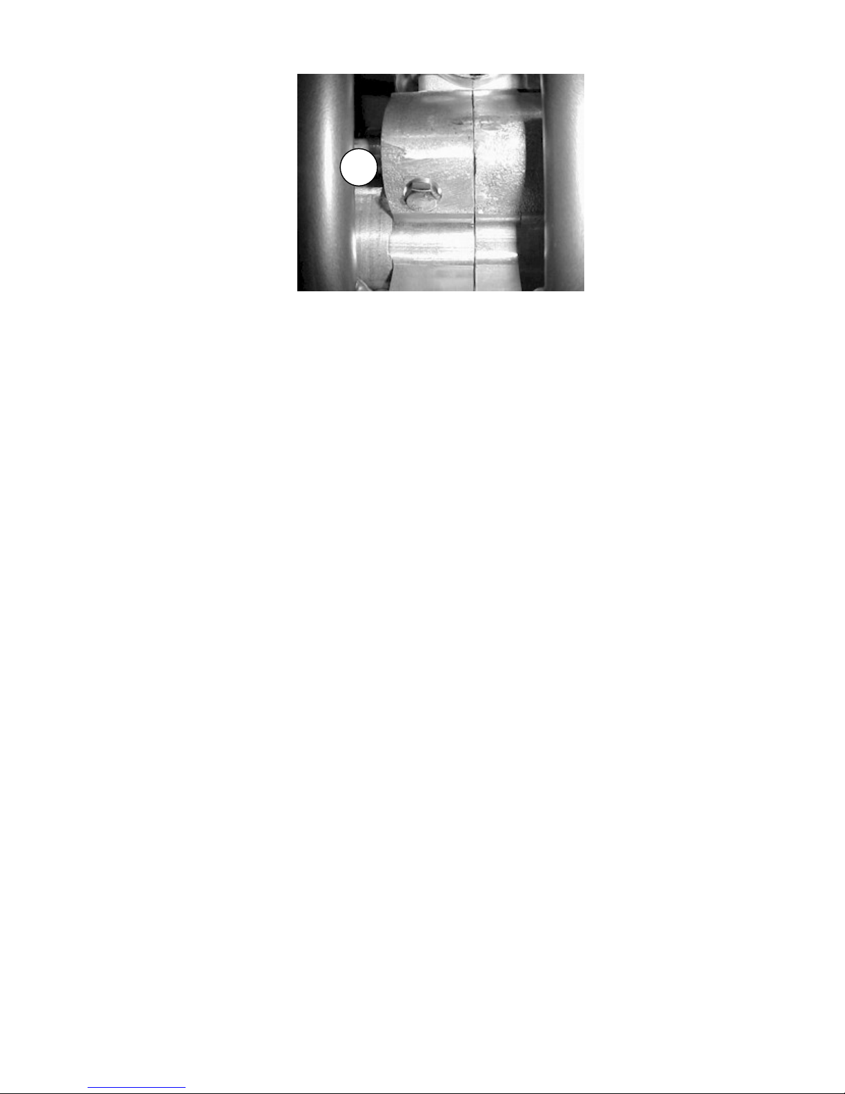
Figure 37
A
To remove radiator cap:
1. Turn the cap counter clockwise to the first stop and wait there for a few seconds.
2. Push the cap down and turn it further in the same direction and remove the cap.
NOTE: Inspect the old coolant for visual evidence of corrosion and abnormal smell.
Tools recommended for impeller service:
• Flat head screwdriver
• 13mm- hex wrench
• 3mm hex key
• 4mm hex key
• 5mm hex key
• 8mm hex key
• Propane torch
• 3/8” diameter x 8” long steel rod
• Hammer
COBRA IMPELLER SERVICE INSTRUCTIONS
1. Remove exhaust pipe and gas tank (you may be using a propane torch in step
12.
2. Remove radiator cap and drain engine coolant by removing the 13mm- hex head
coolant drain plug.
3. If the impeller is damaged or broken completely back flush the coolant system to
ensure no solid pieces are in the system.
4. Drain engine transmission oil by removing drain screw using a 13mm- hex
wrench. (item 2 in the figure below).
5. Remove right side radiator hose and unscrew coolant fitting with a 8mm hex key.
6. Remove ignition cover using a 4mm hex key (four places)
7. Stick a 3mm hex key in the water pump shaft cross hole, and remove belt
retainer screw using a 4mm hex key. (Figure 41 - item 1)
8. Remove belt retainer, water pump belt and water pump fan pulley.
9. Remove bearing retainer screw using a 3mm hex key. (Figure 38 – item 2)
58
Page 60

Figure 38
10. Heat engine case around area of impeller lightly with a small propane torch.
Using a 3/8” diameter x 8” long steel rod, tap impeller assembly out of engine as
shown in figure 39.
Figure 39
CAUTION:
Too much heat can be detrimental to the engine cases.
11. The shaft assembly is serviceable. Use a 4mm hex key to remove impeller
retainer screw. Remove impeller, seal and both bearings. Check shaft for wear in
the area of the seal. If there is any sign of wear (like a groove) replace the shaft.
12. Reinstall new bearings, seal (open side toward impeller) and impeller. Clean all
threads and use green (wicking / bearing retainer) thread locker.
13. Using a liberal amount of grease on the outside seal, bearings and inside of
case, reinstall bearing assembly by using a 0.500” ID by 1.000” OD steel tube 2”
long and tap on end of tube per figure 41.
14. Re-assemble in reverse order of disassembly.
Figure 40
Figure 41
59
Page 61

r
CAUTION:
Clean all threads and use blue (medium strength) thread locker on the belt retaine
screw.
NOTE:
Apply Ultra black Hi-Temp RTV silicon or Teflon pipe sealant to the tapered pipe
threads of the coolant fitting before assembly.
NOTE:
Refill the coolant system with Liquid Performance Propylene Glycol based Mini
Coolant / Antifreeze.
CAUTION:
Do not mix Propylene Glycol based coolant / antifreeze solutions with Ethylene
Glycol based coolant / antifreeze solutions.
60
Page 62

Fuel & Air System
Carburetor:
Tools recommended for carburetor service:
• Small flat head screwdriver
• WD-40
• 8mm socket
Your Cobra is equipped with an adjustable carburetor. Some fine-tuning may be
needed according to weather condition and altitude. Proper jetting is very
important for engine performance and engine life. Serious damage to the engine
can occur if not properly adjusted.
IDLE ADJUSTMENT:
On the left side of the carburetor, there are two adjustment screws. The larger
screw with the knurled head is the idle adjustment screw. To raise the idle, turn
the screw in clockwise (in 1/4 turn increments) and rev the engine after each
CX50 SR Carburetor Ref. Drawing
REF. # PART # DESCRIPTION
1 RCMU0305 CARB SLIDE
2 RCMU0601 NEEDLE
3 ATOMIZER AU2.62
4 MAIN JET
5 PILOT JET
6 CHOKE JET
7 RCMU0301 FLOAT
8 RCMU0102 RUBBER CABLE CAP SEAL
9 RCMU0003 CABLE ADJUSTOR
10
11 RCMU0006 TOP CARB SCREW
12 RCMU0106 CARB TOP
13 ZCMU0007 TOP CARB GASKET
14 RCMU0004 SLIDE SPRING
15 RCMU0205 NEEDLE RETAINER PLATE
16 RCMU0007 NEEDLE CLIP
17 RCMU0204 CHOKE ASS’Y. 2001 CM
20 RCMU0009 FUEL MIXTURE SCREW
21 RCMU0011 IDLE ADJUSTMENT SCREW
25 RCMU0103 FLOAT BOWL GASKET
26 RCMU0107 FLOAT NEEDLE
27 RCMU0012 DIFFUSER
28 RCMU0016 FLOAT RETAINER PIN
29 RCMU0106 FLOAT BOWL
30
RCMU0201 BOTTOM FLOAT SCREW
31
33 RCMU0269 VELOCITY STACK
Figure 42
61
Page 63

adjustment. To lower the idle, turn the screw counter-clockwise.
TOP END JETTING:
Indications that the engine is running too rich (too much fuel for the air) are:
• Engine not revving out or blubbering at high RPMs.
• Engine will not ‘clean out’
• Wet or black spark plug
NOTE: Before changing jetting be sure that the air filter is properly cleaned and
has the usual amount of air filter oil. An overly dirty air filter can cause the engine
to run rich.
If the engine is running rich on the top end it should be leaned out. Leaning it out
can be done by:
1. Changing the main jet to a smaller number.
2. Raising the needle clip (this lowers the jet needle) one notch at a time on the
slide.
Indications that the engine is running too lean are:
• Engine cutting out on top end.
• Engine overheating and ultimately seizure.
• White spark plug
CAUTION:
It is much safer to operate the engine slightly rich as opposed to slightly lean.
This is because an overly rich engine will just run poorly while an overly lean
engine will seize, potentially causing an expensive top end rebuild and a DNF.
To richen the carburetor:
1. Change the main jet one number at a time (larger).
2. Lower the needle clip (raising the jet needle) one notch at a time until the
engine starts to blubber on the top end, then move the clip back up one notch
or until you get the blubber out.
FUEL MIXTURE SCREW
The smaller brass screw that is towards the front of the engine is a fuel mixture
screw. This screw will also richen and lean your engine more on the bottom and
mid-range. In warmer conditions, turn the screw in. In colder conditions, turn the
screw out. Be sure to keep the carburetor very clean and make sure you don't
have water or dirt in the carburetor bowl. Use automotive carburetor cleaner or
WD-40 to clean the carburetor inside and out.
STOCK CARBURETOR SETTINGS
The 2007 CX50 SR stock carburetor settings
from the factory are:
• 60 pilot jet
• 95 main jet
Cleaning the carburetor:
62
Page 64

Clean the carburetor in a well-ventilated area, and take care that there is no
spark or flame anywhere near the working area; this includes any appliance with
a pilot light. Because of the danger of highly flammable liquids, do not use
gasoline or low flash-point solvent to clean the carburetor.
1. Make sure the fuel is shut off.
2. Remove the carburetor.
3. Drain the fuel from the carburetor.
4. Disassemble the carburetor.
5. Immerse all the metal parts in a carburetor cleaning solution.
6. After the parts are cleaned, dry them with compressed air.
7. Blow out the fuel passages with compressed air.
8. Assemble the carburetor
9. Install the carburetor onto the motorcycle.
CAUTION:
1. The motorcycle will only operate properly if the carburetor top is installed
properly with the mounting screws, cable and choke knob oriented as
shown in figure 43.
Figure 43 Proper carburetor top
installation and location of
rectangular slide indexing pin and
vent elbows.
63
Page 65

Reeds:
• The reeds must lay flat on the reed cage.
• If the reed tips aren’t lying flat, replace them immediately.
• The reeds must have a tight seal on the reed cage.
• If the reed is damaged in any way, replace it. This means cracks, chips,
and ruptures. Anything abnormal, replace the reeds.
Take the reed cage out and hold it up to the light and look in through the cage. If
you see light between the reed pedals and the frame, then replace the reeds. If
you do not see light, then the reeds should be ok. (See figure 44)
Figure 44
The presence of light indicates that the reeds should be replaced, or possibly turned over.
Exhaust
The pipe is a crucial element to a motorcycle. Any kinks, dents, or damage done
to the pipe will result in a major performance loss.
NOTE:
Be sure to take the pipe off, and any carbon that may be built up. Carbon build
up is created from exhaust. Exhaust has oils in it, and the oils cling to the walls
of the inside of the pipe. Over a long period of time, the diameter of the pipe will
decrease, due to carbon build up. So it is essential to clear the residue.
CAUTION:
It is important to repack the silencer. Signs of your silencer needing to be
repacked are:
• The bike is louder than normal.
• A loss of power.
64
Page 66
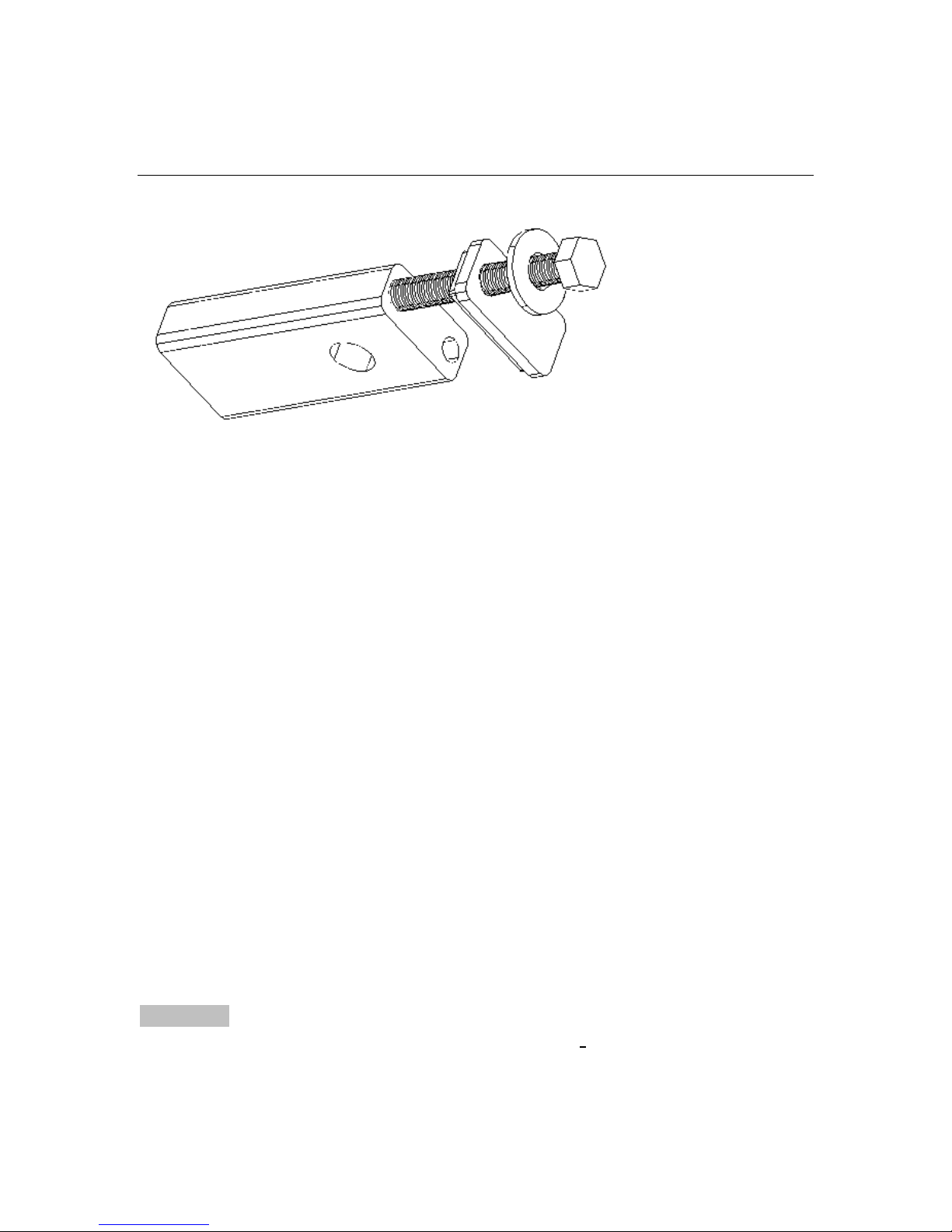
Wheels & Tires
Rear wheel pullers
Disassembly:
1. Remove axle, and
back wheel assembly.
2. Pull the rear wheel
pullers out of the back
of the swing arm.
Figure 45
Rear wheel alignment:
By eye, ensure that the rear sprocket is running true (in-line, planar) with the front
sprocket. When the sprockets are running true, the wheel is properly
straightened, and the chain will run straight.
Brakes
WARNING! Your brakes need a break-in period to achieve maximum brake
power. 30-40 stops will bring the brake to peak performance.
Check before each ride:
• Make sure the brake does not have any leaks by holding the lever in while
checking hose connections.
• Make sure the brake lever pressure is OK by pulling in on the lever and
ensuring full braking performance is achieved before the lever touches the
handlebar. If this is not the case, pump the lever several times until the lever
feels firm.
• Always make sure the rotor and brake pads are free from oil and grease.
Clean the rotor with mild dish soap or alcohol. Contaminated pads must be
replaced.
• Always leave adequate free-play in the lever or pedal.
CAUTION:
This brake system uses only DOT 4 or 5.1 brake fluid!
This portion will be updated shortly. Check our website
www.cobramotorcycle.com for updates.
65
Page 67

Front Forks
Tools recommended for front fork service:
• Flat head screwdriver
• Hammer
• Pick
• Seal driver MCMUTL02
•
9/16” (loose 14 mm) wrench
•
25mm wrench or socket
•
5 wt fork oil
FORK DISASSEMBLY PROCEDURES:
1. Using the 25mm wrench, remove the fork cap.
2. Drain the fork oil into a suitable container.
3. Disconnect the fork cap from the damper rod (9/16” wrench & 25mm wrench).
4. Disconnect the damper assembly from the fork leg by removing the large
aluminum bolt from the bottom of the fork leg (22mm wrench).
5. Pry the dust seal (swiper) from its position with a small screw driver.
6. Using a pick, remove the wire retaining ring holding the fork seals into place.
7. ‘Pop’ the fork seal out by forcibly pulling on both ends of the fork tube
assembly, thus separating the inner from the outer tube.
8. Remove the bushings
9. Clean all components to be reused.
FORK ASSEMBLY PROCEDURES:
Figure 46
CAUTION:
Make sure all components are clean before assembly.
CAUTION:
Be sure to apply oil to the new fork seal and other components before installing.
1. Slide dust seal (swiper) (#6) onto lower fork leg.
2. Slide retaining ring (#5) onto lower fork leg.
66
Page 68

3. CAREFULLY slide seal (#4) onto lower fork leg with spring facing away from
snap ring.
CAUTION:
It is helpful to cover the sharp corners of the fork leg with tape or thin plastic
before sliding on the new seal. Also take care that the inner lip is not folded over
when installing.
4. Slide bushing (#3) onto lower fork leg.
5. Install the glide ring into groove on lower fork leg.
6. Slide the bushing over the glide ring about 1/4" to hold the glide ring in the
groove.
7. Insert the lower leg assembly into the upper fork tube about 5-6".
8. Use a seal driver to drive the seal into the upper tube.
9. Install the retaining ring. Make sure it is properly seated in the groove.
10. Snap the dust seal (swiper) into the groove in the upper tube.
11. Reinstall the damper cartridge assembly to the fork leg. Secure the large bolt
with 22 mm wrench to 35 ft-lb with green thread locking agent.
12. Fill with 3.6 oz (107 ml) 5 wt fork oil should measure 6 mm (0.25”) above the
damper cartridge tube with spring removed. (This oil volume works out to
leave an oil height of 120mm from top of outer tube with forks collapsed,
damper rod down, and spring removed).
13. Install the fork spring
14. Connect the cartridge rod to the cap and tighten to 12 ft-lb (16 Nm).
CAUTION:
The damper rod is hollow and will break if the nut is over tightened (proper torque
is 12 ft-lb, 16 Nm).
Because of different rider weights, sizes and riding styles, we offer various
suspension options:
See Optional Components section of this manual for details on these and other
optional components for your Cobra Motorcycle.
67
Page 69

Rear Shock
The rear shock is fully serviceable but it is recommended that only trained
professionals should service your shock. Contact Cobra or PR2 for questions
and service of your CX50 sr shock.
Shock preload
Shock Damping
Figure 48
Figure 47
68
Page 70

Tuning
Gearing
For a bike with a centrifugal clutch, it’s better to be geared too low than too
high.
What happens with improper gearing?
• Poor performance
• Not enough top end speed
• No snap
• Over heat clutch
• Premature failure of engine seals, bearings, & electronics
• High clutch wear
Condition
Mud
Sand
Hills
Hard Pack
Throttle Blipper (novice)
Gear Taller Gear Lower
*
*It may be helpful to set up the clutch to hit early for smooth power delivery
69
Page 71

Front Sprocket
13
13
13
13
13
13
13
13
13
13
14
14
14
14
14
14
14
14
14
14
15 33 2.20
15 34 2.27
15 35 2.33
15 36 2.40
15 37 2.47
15 38 2.53
15 39 2.60
15 40 2.67
stock
15 41 2.73
15 42 2.80
Rear
Sprocket Gear Ratio
33 2.36
34 2.43
35 2.50
33 2.54
36 2.57
34 2.62
37 2.64
35 2.69
38 2.71
36 2.77
39 2.79
37 2.85
40 2.86
38 2.92
41 2.93
39 3.00
42 3.00
40 3.08
41 3.15
42 3.23
Ratio Write © Cobra R&D
2004
70
Page 72

Suspension
Adjustment:
1. Front forks
1.1. Fork oil
1.1.1. Oil type
1.1.1.1. Heavier weight oil – more damping – slower responding
1.1.1.2. Lighter weight oil – less damping – quicker responding
1.1.2. Oil quantity / level
1.1.2.1. Greater quantity / higher level – greater bottoming
resistance, stiffer near the end of the travel.
1.1.2.2. Smaller quantity / lower level – less bottoming resistance,
less stiff near the end of the travel.
1.2. Fork spring
1.2.1. Stiffer spring (higher spring rate) – stiffer throughout the travel.
1.2.2. Less stiff spring (lower spring rate) – less stiff throughout the travel.
1.3. Gas pressure – always bleed off any pressure.
1.4. Fork height
1.4.1. Rise in clamps for quicker turning.
1.4.2. Lower in clamps for improved straight line stability.
2. Rear shock
2.1. Preload adjustment
2.1.1. More preload (greater distance) – less race sag.
2.1.2. Less preload (smaller distance) – more race sag.
2.2. Shock spring
2.2.1. Stiffer spring – stiffer throughout the travel.
2.2.2. Less stiff spring – less stiff throughout the travel.
2.3. Compression damping
2.3.1. Harder (more damping, slower) – adds resistance to the
suspension motion when the suspension is compressing.
2.3.2. Softer (less damping, quicker) – reduces resistance to the
suspension motion when the suspension is compressing.
2.4. Rebound damping
2.4.1. Harder (more damping, slower) – adds resistance to the
suspension motion when the suspension is returning to full length.
2.4.2. Softer (less damping, quicker) - reduces resistance to the
suspension motion when the suspension is returning to full length
Front Forks Bottoming Too Frequently Fork oil level
If the front forks bottom harshly more than a couple of times per lap and the fork
springs are proper for the weight of rider (as detailed above), try raising the fork
oil level in increments of 10mm. Raising the fork oil level, reduces the air volume,
and increases the stiffness of the forks late in the travel, thus adding a
progressive’ feel.
Front forks feel too stiff over small bumps. Fork oil weight
71
Page 73

If the forks feel too stiff over small bumps try decreasing the weight (increasing
the viscosity) of the fork oil.
Rear suspension troubleshooting. Damping
Always start with standard settings and make damping changes in no more than
two click increments and only make one change at a time.
Symptom Action
Rear end feels stiff on small bumps Softer compression damping
Rear end ‘sways’ on straights Harder compression damping
Bike tends to jump ‘rear end high’ Harder rebound damping
Bike tends to jump ‘rear end low’ Softer rebound damping
Frequent rear end bottoming Harder compression damping
Bottoms after end of continuous bumps Softer rebound damping
Rear end ‘kicks’ over square edge bumps 1) Harder rebound, 2) Softer
Compression
Proactive Suspension Adjustments
Once you have the suspension adjusted for decent overall feel, you can make
proactive adjustments when faced with different racing conditions.
Situation Actions
Sand track Lower the rear end (increase race sag).
Sand track Stiffer compression and rebound damping.
Long fast track Lower the forks in the clamps by 3 mm.
Tight slow track Raise the forks in the clamps by 3 mm.
Mud track Lower the bike if the rider has difficulties
touching the ground.
Carburetion
Although your Cobra is sent from the factory with the carburetor jetted for optimal
performance, you may find it necessary to adjustment your particular jetting due
to current weather conditions, altitude, fuel variations, and/or engine
modifications.
CAUTION:
Proper jetting is very important for engine performance and engine life.
Symptoms of improper jetting are listed below.
• Symptoms of incorrect oil or oil / fuel ratio
o Poor acceleration
72
Page 74

o Misfire at low engine speeds
o Excessive smoke
o Spark plug fouling
o Excessive black oil dripping from exhaust system
• Symptoms of too rich a fuel mixture
o Poor acceleration
o Engine will not ‘rev’ out, blubbers on top
o Misfire at low engine speeds
o Excessive smoke
o Spark plug fouling
o Wet, black, or overly dark spark plug (when removed for inspection)
• Symptoms of too lean a fuel mixture
o Pinging or rattling
o Erratic acceleration
o Same actions as running out of fuel
o High engine temperature
o White spark plug (when removed for inspection)
NOTE:
When inspecting the spark plug to evaluate jetting, a properly jetted machine will
produce a spark plug that is dry and light tan in color.
Environmental and altitude related mixture adjustments
Condition Mixture will be Required adjustment
Cold air Leaner Richer
Warm air Richer Leaner
Dry air Leaner Richer
Very humid air Richer Leaner
Low altitude Standard None
High altitude Richer Leaner
Low barometric pressure Richer Leaner
High barometric pressure Leaner Richer
NOTE:
• Before making any carburetor jetting changes verify that:
o You are using the proper fuel and oil
o The fuel is fresh and uncontaminated
o The oil and fuel have been mixed in the proper ratio
o The carburetor is clean (no plugged jets)
o The air filter is properly clean and oiled
o The float height is within proper specification (proper measuring technique
is described later in this section)
NOTE:
Perform all jetting changes on a motorcycle that has been warmed up to proper
operating temperature.
The carburetor on your Cobra motorcycle is quite adjustable. Figure 49 shows
its range of adjustment and in particular what adjustable component affects what
73
Page 75

range of operation (specifically throttle position).
Figure 49
FUEL SCREW ADJUSTMENT: Adjust for maximum idle speed
The fuel adjustment screw is located on the left side of the carburetor. It is the
smaller of the two adjustment screws and requires the use of a small flat blade
screw driver for adjustment. After adjusting for maximum idle speed, use the idle
screw to adjust the desired idle speed.
NOTE:
If the fuel screw requires more than 3 turns out, replace the pilot jet for one that is
one size richer (larger number) then readjust the fuel screw.
IDLE ADJUSTMENT: Adjust for desired idle speed
The idle speed screw is located on the left side of the carburetor. It is the larger
of the two screws on the side of the carburetor and is unique with its knurled
head for easy fingertip adjustment. To raise the idle, turn the screw in, clockwise,
(in 1/4 turn increments) and rev the engine after each adjustment. To lower the
idle, turn the screw counter-clockwise.
TOP END JETTING: Adjust for clean full throttle acceleration
Jet your top end (main jet) based on the acceleration of your Cobra Motorcycle
on the longest straight at the track. Observe any of the lean or rich symptoms
(spark plug appearance and bike performance) listed above and change your
jetting accordingly.
PART THROTTLE Adjust for desired acceleration
Using an area of the track that allows the rider to operate and mid throttle and
transition (accelerate, or ‘roll on’) from closed, or mostly closed throttle, to a
larger throttle opening. Observe the rich and lean symptoms listed above.
Adjust the jet needle position by moving the clip from its current position (move
the clip higher on the needle to make the bike run leaner, or move the clip lower
on the needle to make the bike run richer) to one higher or lower.
74
Page 76

Troubleshooting
1) Engine operates erratically
a) Carburetor top is installed backwards
b) The carburetor slide indexing pin is missing
c) A carburetor vent elbow is plugged or has fallen out
d) Faulty stator
e) An air leak
i) Base gasket
ii) Intake / reed gaskets
iii) Crank seals
iv) Crank case gasket
2) Engine is down on power
a) Clutch engagement is not set properly
b) Jetting is incorrect
c) Silencer needs repacked
d) Exhaust pipe
i) Has excess carbon buildup
ii) Has large dent in it
e) Compression is low
i) Piston
ii) Rings
f) Reeds are damaged
g) Ignition timing is incorrect
h) Stator needs replaced
3) Engine is excessively loud
a) Silencer needs repacking
4) Engine ‘blubbers’ at high RPMs
a) Jetting too rich
b) Stator needs replaced
5) Engine won’t start
a) Fuel
i) None in tank
75
Page 77

ii) Is sour or bad
b) Carburetor is dirty
c) Ignition
i) Spark plug fouled
ii) Spark plug cap off
iii) Engine Shut-off ‘kill’ switch is shorted
iv) Bad electrical ground
v) Stator winding damaged
d) Exhaust is plugged with object of flooded fuel
e) Engine is flooded
f) Cracked, broken, or jammed reed pedal
g) Excessive piston or cylinder wear
h) Clutch bolt or shoe dragging on basket (drum).
6) Engine won’t idle
Idle knob needs adjusted
a)
b) Carburetor jets are dirty
Index
Air Filter ........................................16
Bars and Controls.........................22
Base Gasket Selection..................43
Break-In.......................................... 8
Carburetor
Parts..........................................23
Service......................................61
Specifications..............................5
CFD Cobra Frictional Drive...........20
Chain
Adjustment ................................13
Chassis
Specification................................ 5
Clutch
Parts..........................................27
Service......................................49
Clutch Lubricant
Replacing ..................................12
Compression test..........................43
Cooling System.............................56
Cylinder head
torque ..........................................7
Electrical
Parts..........................................25
Engine
Specifications ..............................5
Exhaust.........................................64
Parts..........................................30
Fork oil replacement......................19
Forks
Parts..........................................31
Service.......................................66
Frame Parts ..................................33
Frictional Drive ..............................20
Front Brake
Parts..........................................35
Front Wheel Parts .........................36
Fuel System
Parts list.....................................61
76
Page 78

Service......................................61
Hardware
Frame........................................33
Plastic........................................37
Ignition
Parts..........................................28
Service......................................54
Timing .......................................55
Jetting
How To......................................61
Stock........................................... 5
Troubleshooting.........................72
Lubrication
Recommended............................ 5
Maintenance
Schedule ...................................10
Tips ........................................... 10
Oil
Recommended............................ 5
Optional components......................6
Parts
Bars and Controls......................22
Bottom End & Transmission...... 26
Carburetor.................................23
Clutch & Kick Starter................. 27
Coolant System...................21, 24
Electrical.................................... 25
Engine.......................................26
Exhaust .....................................30
Forks......................................... 31
Frame........................................33
Front Brake ...............................35
Front Wheel............................... 36
Ignition & Water Pump .............. 28
Plastic & Seat............................ 37
Rear Brake................................38
Rear Wheel ...............................39
Shock.........................................40
Swingarm...................................41
Top End.....................................29
Triple Clamps ............................31
Plastic & Seat Parts.......................37
Pullers...........................................65
Rear Brake
Adjustment.................................14
Parts..........................................38
Rear Wheel
Parts..........................................39
Pullers........................................65
Reeds............................................64
Shock
Parts..........................................40
Service.......................................74
Slip Clutch.....................................20
Spark Plug
Recommended ............................5
Specifications..................................5
Starting............................................9
Stator
torque ..........................................7
Suspension ...................................74
Swingarm Parts.............................41
Top End
Parts..........................................29
Service.......................................42
Torque Values.................................7
Transmission Lubricant
Replacing...................................12
Troubleshooting ............................75
Jetting........................................72
VIN reading...................................11
WARNING.......................................2
Water Pump
Parts..........................................28
Wheels
Service.......................................65
1
 Loading...