

Cobra 2007 CX65 Owner's Manual
2007
20072007
2007
CX65
CX65CX65
CX65
Owners
OwnersOwners
Owners
Parts
Parts
PartsParts
Service
Service
ServiceService
Tuning
Tuning
TuningTuning
DISCLAIMER OF WARRANTY
This motorcycle is sold “as is” with all faults, obvious or not. There are no warranties
expressed or implied, including any warranty of merchantability and warranty of fitness
for any particular purpose.
“WARNING”
THE COBRA CX65 IS A COMPETITION MODEL ONLY AND IS NOT
MANUFACTURED FOR, NOR SHOULD IT BE USED ON PUBLIC STREETS, ROADS
OR HIGHWAYS.
THE USE OF THIS BIKE SHOULD BE LIMITED TO PARTICIPATION IN
SANCTIONED COMPETITION EVENTS UPON A CLOSED COURSE BY A
SUFFICIENTLY SKILLED RIDER AND SHOULD NOT BE USED FOR GENERAL
OFF-ROAD RECREATIONAL RIDING.
IMPROPER USE OF THIS MOTORCYCLE CAN CAUSE INJURY OR DEATH.
THIS BIKE IS INTENDED FOR EXPERIENCED RACERS ONLY AND NOT FOR
BEGINNERS.
IT IS YOUR RESPONSIBILITY AS THE OWNER OF THIS COBRA MOTORCYCLE
OR AS THE PARENT, OR LEGAL GUARDIAN OF THE OPERATOR, TO KEEP THIS
COBRA MOTORCYCLE IN PROPER OPERATING CONDITION.
THIS BIKE WAS DESIGNED FOR RIDERS THAT WEIGH LESS THAN 80 LBS WITH
FULL RIDING GEAR AND SHOULD NOT BE OPERATED BY RIDERS THAT WEIGH
MORE THAN THAT.
BE SURE THAT THE RIDER ALWAYS WEARS ADEQUATE SAFETY GEAR
EVERYTIME HE OR SHE RIDES THEIR COBRA MOTORCYCLE.
IMPORTANT SAFETY NOTICE
Failure to follow WARNING instructions could result in severe injury or death to
the machine operator, a bystander, or a person inspecting or repairing the
machine.
CAUTION:
A CAUTION indicates special precautions that must be taken to avoid damage to
the machine.
NOTE:
A NOTE provides key information to make procedures easier or clearer.
MCCX6507.1

Table Of Contents
GENERAL INFORMATION.......................................................................................3
SPECIFICATIONS - GENERAL..........................................................................................3
OPTIONAL COMPONENTS..............................................................................................4
SPECIFICATIONS - TORQUE VALUES..............................................................................5
BREAK-IN PROCEDURE.................................................................................................6
STARTING PROCEDURE.................................................................................................7
MAINTENANCE..........................................................................................................8
TIPS.............................................................................................................................8
SCHEDULE....................................................................................................................8
REPLACING TRANSMISSION / CLUTCH LUBRICANT.......................................................10
CHAIN ADJUSTMENT...................................................................................................11
AIR FILTER CLEANING................................................................................................12
FORK OIL REPLACEMENT ...........................................................................................13
PARTS.........................................................................................................................14
PARTS – AIRBOX & INLET SYSTEM .............................................................................14
PARTS – BARS AND CONTROLS ...................................................................................15
PARTS - CARBURETOR................................................................................................16
PILOT JET................................................................................................................16
MAIN JET.................................................................................................................16
PARTS – COOLANT SYSTEM........................................................................................17
PARTS – ELECTRICAL SYSTEM....................................................................................18
PARTS – ENGINE CLUTCH ...........................................................................................19
Parts – Engine – Clutch / Kick Cover ....................................................................20
Parts - Engine - Ignition Side.................................................................................21
Parts - Engine – Kick Mechanism..........................................................................22
Parts – Engine – Shift Mechanism .........................................................................23
Parts – Engine – Top End......................................................................................24
Parts - Engine - Transmission................................................................................25
PARTS – EXHAUST SYSTEM.........................................................................................26
PARTS – FORKS – LEG ASSEMBLY...............................................................................27
PARTS – FRAME & TRIPLE CLAMPS.............................................................................28
PARTS – FRONT WHEEL & BRAKES.............................................................................29
PARTS –BODYWORK...................................................................................................30
PARTS – REAR BRAKE ................................................................................................31
PARTS – REAR WHEEL................................................................................................32
PARTS – SHOCK..........................................................................................................33
PARTS – SWINGARM ASSEMBLY..................................................................................34
SERVICE.....................................................................................................................35
ENGINE SERVICE........................................................................................................35
Base Gasket Selection............................................................................................36
FUEL & AIR SYSTEM ..................................................................................................39
TUNING ......................................................................................................................42
1

GEARING....................................................................................................................42
SUSPENSION...............................................................................................................43
CARBURETION............................................................................................................44
TROUBLESHOOTING..............................................................................................47
INDEX .........................................................................................................................48
2
General Information
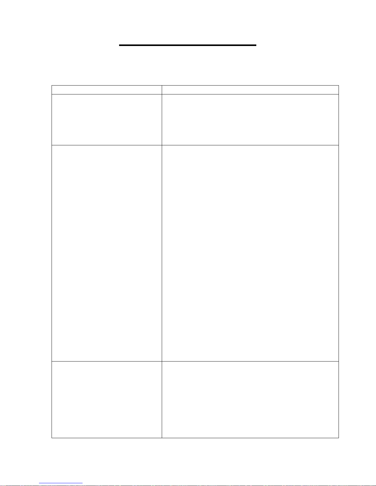
Specifications - General
Items CX65
Dimensions
Wheelbase 40.9” (1040mm)
Wheel size 12” (305mm) rear, 14” (356mm) front
Seat height 29.9” (760mm)
Engine
Type 2-stroke, single cylinder, reed valve
Cooling system Liquid-cooled
Coolant Liquid Performance Mini Coolant or Antifreeze
Displacement 64.9 cc
Bore and stroke 44.5 mm x 41.7 mm
Ignition system Electronic, digital advance
Spark plug Champion 8339-1, 8332-1 hotter, 8904-1 colder
Gap 0.023” – 0.025” (0.58 – 0.64 mm)
Ignition timing Digital advance (set at TDC)
Fuel type High octane pump gasoline
Oil type Cobra Venom 2-cycle Race Oil
Fuel / oil mix ratios Between 32:1 and 40:1 (after engine Break-In)
Carburetion 24 mm VM Mikuni
Slow (Pilot) Jet 40
Float Height
Transmission
Speed 6 speed
Final drive ratio 14/48 or 13/46
Chain 116 links 420
Transmission / clutch oil type Quality gear lubricant
3
Main Jet 230
Quantity 530 ml (18.0oz)
Chassis
Front tire 60/100 – 14
Rear tire 80/100 – 12
Front fork Marzocchi 35mm USD, Compression adjustable
Fork oil type SAE 10 weight
Fork oil amount 210 ml (7.1oz)
Spring Preload Length 178mm (49 N/mm
Rear shock Öhlins: Compression & Rebound Adjustable
Spring rate 280 lb/in (49 N/mm)
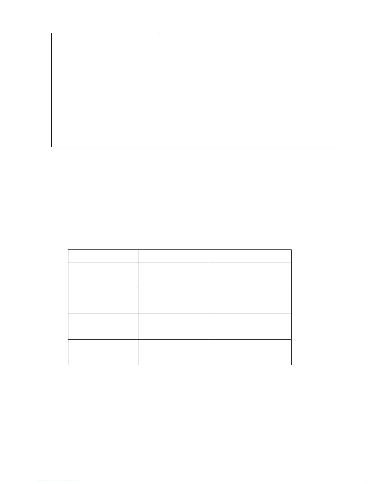
Optional Components
Call your dealer, or the factory, for details
• Carburetor jets
• Pre filter for the airbox
• Tires, tubes or ‘Tire Balls’
• Sprockets
o Front
o Rear
• Suspension Springs
Weight of Rider (lb)
less than 75 lb 42 N/MM
75-90 lb 0.23 kg/mm
90-100 lb 0.26 kg/mm
Greater than 100 0.27 kg/mm
Fork Spring Shock Spring
SCC60240P
45 N/MM
KCC60024
KCC60026
KCC60028
SCC60260P
49 N/MM
SCC60280P
53 N/MM
SCEX1300
4

Specifications - Torque Values
Fastener
Cylinder head
nuts
Crankcase
bolts
Spark plug (SP) (SP) (SP) M14 x 1.25
Stator bolts 2.1 25 2.8 M5 X 0.8
Stator cover
bolts
Clutch cover
bolts
Clutch nut 35 420 47 M10 x 1.25*
Front axle bolt 10 120 13.5 M14 x 2.0
Front axle
pinch bolt
Engine mount
bolts
Swingarm
Pivot
Intake manifold
bolts
ft-lb in-lb Nm
12.5 150 17 M7 x 1.0
8.8 105 12 M6 x 1.0
1.7 20 2.3 M4 X 0.75
5.8 70 7.9 M6 X 1.0
7.4 88.5 10 M6 X 1.0
22 265 30 M8 X 1.25
21 250 28 M12 X 1.5
4.6 55 6.2 M6 X 1.0
Torque Value
Size &
Remarks
Rear Axle Bolt 25 300 34 M14 X 1. 5
Rear Sprocket
Bolts
Triple clamp
bolts
Fork cap 15 177 20
Fork Damper
Nut
Ignition rotor
nut
* Apply high strength thread locking agent when installing
(SP) To apply the proper torque to the spark plug when inserting, one must first
screw the spark plug in until the metal gasket ring causes resistance and then
turn another 1/8 to ¼ turn.
5
20 240 27 M8 X 1.25
6 72 8 M6 x 1.0
11 133 15
40 480 54 M10 x 1.25*

Break-In Procedure
Your Cobra CX65 is a close-tolerance high performance machine and break-in
time is very important for maximum life and performance. The CX65 can be
ridden hard after the first ½ hour break-in time but it is recommended that no
adjustments are made to the carburetion or suspension until the full 8 hours of
bike break-in has elapsed. Also, after the engine, transmission, and drive train
have been broken-in for the full 8 hours, the bike will be faster!
Use a fuel / oil mixture of 32:1 for the full 8 hour break-in period. Be sure to use
high octane pump gas with Cobra’s specially formulated Cobra Venom 2-cycle
Race Oil. (Part # MCMUOL02)
CAUTION:
Failure to use proper fuel, oil, or fuel/oil mixture may result in premature engine
wear or damage to the machine.
Adhering to the following break-in schedule will result in long lasting high
performance machine.
• Start bike on stand
• First 5 minute period, operate the bike on the stand with a combination of idle
and high RPM operation. (avoid prolonged high RPM but spin the rear
wheel good at least once or twice per minute)
• Allow bike to cool
• Ride for 15 minutes maximum (avoid prolonged high RPM operation and
avoid abusing the clutch).
• Cool and inspect bike for loose fasteners.
• Next ½ hour of operation, avoid prolonged operation at Wide Open Throttle.
• After 1 hour of operation
o Check for loose bolts and nuts on the bike and retighten as
necessary (proper toque values are listed under Specifications).
o Clean the carburetor bowl.
o Change the transmission / clutch lubricant.
• After 8 hours of operation
o Change the fork oil.
o Have a Certified Cobra Mechanic change the shock oil.
• Your bike is now ready for the highest level of competition!
NOTE:
During break-in the bike will likely lose some engine coolant through the radiator
overflow hose. Losing up to 4 oz (120 ml, ½ cup) is normal. Proper coolant level
will cover the top of the radiator cores. Removing the radiator cap and looking
inside is the only way to check the coolant level.
6

Never open the radiator cap of a machine that has a hot or warm engine or one
that has recently been ridden. Burning and scalding could occur.
CAUTION:
It is important that the radiator cap is installed correctly and completely otherwise
engine damage could occur.
Starting Procedure
Before starting the machine inspect the following:
• Check for proper tire pressure in both tires.
• Observe the chain tension and adjust if necessary.
• Observe the coolant level and fill if necessary.
• Verify that the chain rollers and sliders do not have improper wear.
• Verify that the handlebars are tight.
• Check the throttle for smooth operation and sound closing.
• Check for loose bolts and nuts, and re-torque as necessary.
• Verify that the air filter is clean and properly saturated with oil.
• Insure that the fuel tank contains an adequate volume of fuel / oil mixture to
complete the distance required. (High octane pump gas with Cobra’s
specially formulated Cobra Venom 2-cycle Race Oil)
• Turn the fuel on by rotating the fuel petcock lever to the vertically downward
position.
CAUTION:
For best results from your Cobra Motorcycle use only the recommended fuels.
‘Race’ fuels can be used, however, they are not required with the stock engine,
and the engine will require addition attention to maintain proper jetting as
weather condition change throughout the day.
Always wear a helmet and other protective riding gear.
When your pre-ride inspection is complete the bike may be started. For a cold
engine follow this procedure.
1. Place the motorcycle on a stand of sufficient strength that positions the
motorcycle in a level upright position with the rear wheel off the ground.
2. Engage the choke by pulling out on the choke button until it stops.
3. Kick start the engine.
4. Rev the engine in short spurts, turning the throttle no more than 1/4 open
until the engine will run without the choke.
5. Verify a functional engine shut-off switch by shutting off the engine.
6. Restart the engine and proceed with riding when the engine is sufficiently
warm (i.e. the side of the cylinder is warm to touch).
7

CAUTION:
Never rev an engine full throttle when it's cold or slightly warmed up. This may
lead to premature wear of engine components or complete cold seizure of the
engine.
CAUTION:
Cobra recommends that you tell your child to take it easy the first couple of
minutes in practice until the engine comes up to full operating temperature.
Maintenance
It is important that you adhere to this maintenance schedule so as to promote the
longevity of your Cobra Motorcycle.
Tips
1. Cobra lubricants:
a. Use only high quality transmission oil designed specifically for two-
stroke racing engines.
b. Cobra Two Cycle Oil exceeds the JASO FD & ISO-L-EGD
specifications, which are the world’s most stringent requirements on
lubrication, detergency, and smoke.
2. Fill your transmission only with the recommended amount of oil. Overfilling
may lead to premature seal failure.
3. The cylinder base gasket has been ‘fitted’ for your engine. See the service
section of this manual for instructions how to properly size a base gasket
during an engine rebuild.
4. Evaluate the bikes jetting only after it has been warmed up to race
temperatures.
5. A properly maintained machine is safer, faster, and more fun to ride.
6. New chains will stretch on first use. Never install a new chain prior to a
race. Always ‘break’ them in during practice.
7. Your Cobra Motorcycle has a 10 digit VIN (Vehicle Identification Number).
The first two digits indicate the model and the seventh indicates the model
year (MY).
a. Example, CXxxxx7xxx is a 2007 MY CX65.
Schedule
• Between each ride
o Check the air filter (clean and re-oil as necessary).
o Insure the smooth operation of the throttle cable (throttle soundly
‘clacks’ shut).
o Check for frayed strands of the throttle cable inside the throttle housing
and replace if necessary.
o Check for adequate tire pressures and adjust if necessary.
o Check all nuts and bolts for proper torque and re-torque if necessary.
8

o Spray all moving parts with WD40 or other water displacing oil.
o Check drive chain for
Proper tension and adjust if necessary.
Adequate lubrication and lubricate if necessary.
o Insure that the ignition stator and rotor are clean and dry.
o Check the frame for cracks in the metal or cracks in the paint that
might indicate that the metal has been stressed beyond it’s safe limits.
Replace or get properly re-welded as necessary.
o Check the spokes for tightness and adjust if necessary.
o Check the rims and hubs for signs of stress, like cracks around the rim,
spokes and hub.
• Every 2 hours of operation
o Replace the transmission oil.
• Every 10 hours of operation
o Replace the fork oil.
o Have the shock oil replaced by a Certified Cobra Mechanic.
CAUTION:
If you ever need to weld anything on the bike, disconnect the spark plug cap,
unplug the ignition, disconnect the kill switch, scrape the paint bare near the area
to be welded and put the ground clamp as close to the area to be welded as
possible.
Be sure the fuel tank and carburetor have been removed and safely located
away from the welding process.
The frame is a combination of HSLA steel and 4130 Chrome Moly and it is
important to weld it with the proper rod and heat settings set as light as possible.
Cobra recommends replacing the frame with a new one if the old one becomes
damaged. Use ER70S6 filler if welding on the frame.
9
Replacing Transmission / Clutch Lubricant
Tools needed:
• High quality transmission oil
• 8 mm Allen wrench
Procedure:
1. Begin this procedure with a bike that has been ridden more than 5 minutes
but less than 10 minutes. It is desired to have the engine warm enough so
that the oil is ‘runny’ but not so hot that there is risk of being burned by the
engine or the oil.
Hot oil and hot components on
the motorcycle may cause
burns.
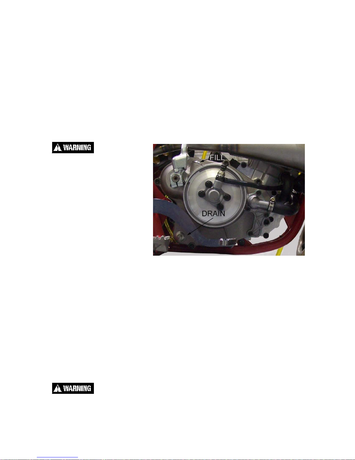
2. Lean the bike against
something or set on stand
with oil drain hole.
3. Using a 8mm Allen wrench,
remove the oil drain bolt
located on the right side of
the engine, on the clutch
cover, near the brake lever
(See Figure 1).
NOTE: You may need to adjust the brake pedal (up or down) to gain access to
the drain bolt.
4. After it has drained, reinstall the bolt being sure that the plastic gasket is in
place. Torque to 15 Nm (11 ft-lb).
5. Remove oil fill plug with an 8mm Allen wrench.
6. Carefully pour 530ml of transmission oil into the oil fill opening.
7. Reinstall the oil fill plug making sure the plastic gasket is in place.
NOTE: Filling after an engine rebuild required additional transmission fluid. If the
engine is completely flushed of oil, refill with 560ml.
Always capture and dispose of used oil properly (all auto parts stores accept
used oil). Dumping oil on the ground is illegal, inconsiderate, and can get you
disqualified from a race weekend quicker than cutting the track.
10
Chain adjustment
Tools required for chain adjustment
• 22 mm wrench or socket
• 2 - 11 mm open-end wrenches
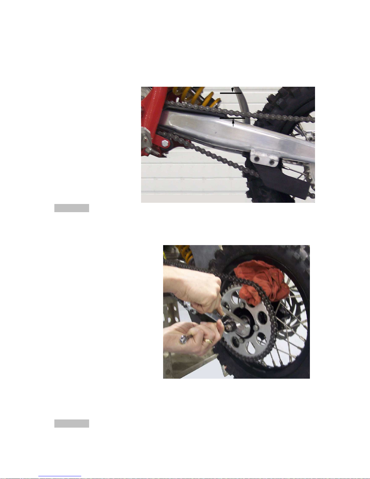
1. Make sure that the
rear wheel is aligned
properly.
2. For proper
adjustment, the chain
should have 35 mm
free movement just
behind the chain
block with no load on
the bike (Figure 2)
CAUTION:
Sit on the bike and verify
that the chain has a
minimum of 12mm (1/2”) free movement when the chain is at its tightest point.
3. If the chain requires
adjusting, loosen the axle
with a 22mm wrench, and
loosen the jam nut with an
11mm wrench. Tighten the
chain by rotating the
adjustor bolts clockwise
(CW) or loosen the chain by
rotating the adjustor bolts
(CCW).
4. Put a rag between the
sprocket and chain, and roll
the wheel backward to pull
the chain adjustor blocks
tightly against the adjustor
bolts (Figure 3).
5. Retighten the axle bolt to 25
ft-lb (34 Nm).
6. Retighten the adjustor jam nuts.
CAUTION:
Always check rear brake adjustment and free-play after adjusting the chain.
Figure 2.
Figure 3.
11

Air Filter Cleaning
Tools recommended for air filter maintenance:
• 4 mm hex key (Allen)
• Foam filter oil
Procedure
1. Removed seat with the 4mm hex key.
2. Unhook the air filter wire from its perch
3. Carefully remove the air filter and
frame out the top of the airbox making
sure not to dislodge any dirt into the
intake tract.
4. Clean the filter in a nonflammable
solvent to remove the filter oil.
Do not clean the air filter with gasoline or other highly volatile petroleum product.
Diesel fuel or kerosene would be preferred but caution should still be taken. Hot
soapy water works well.
5. Clean the filter in hot soapy water to
remove all dirt particles.
6. Allow it to dry thoroughly.
7. Saturate with filter oil and remove
excess.
8. Apply a thin coating of grease around
the sealing lip of the filter.
NOTE:
It is very important to keep the air filter clean
and properly oiled with high quality waterresistant foam filter oil. Apply oil
consistently because varied amounts of oil
will affect carburetor jetting.
9. Reinstall the filter assembly by pushing
it down and forward into the airbox
making sure the lip of the filter cage is properly seated into its receptacle
(figure 5). Reinstall the air filter cap and holding wire.
NOTE:
Make sure you change or clean your filter after each moto. We recommend
carrying multiple filters in your toolbox, one for each practice session and moto.
Figure 4.
Figure 5.
12
Fork Oil Replacement
Requirements
• 19mm and 27mm combination wrench
• 6mm and 10mm hex key (Allen)
• Flexible retrieving tool
• 10w fork oil (approximately 210cc per fork leg)
Disassembly
1. Remove the front wheel and front brake caliper.
2. Remove the fork legs from the triple clamps.
3. Perform the following on each fork leg:
a. Remove the fork cap using a 27mm wrench.
b. Lower the fork tube to expose the fork spring.
c. Pull the fork spring down from the fork cap to
expose the damper rod lock nut. Secure this nut
using a 19mm wrench.
d. With a 19mm wrench on the damper rod nut, use
a 27mm wrench to free the fork cap from the
damper rod.
e. Remove the 19mm wrench and allow the damper
rod to fall into the damper tube.
f. Remove the fork spring and spacer.
g. Invert the fork while pumping the damper rod
assembly several times to help the oil drain.
Assembly
1. Completely collapse the outer fork tube onto the stanchion tube. Add enough
oil to the fork to fill the cartridge tube. Pump the damper rod up and down
slowly to help the assembly fill with oil.
2. Once the cartridge assembly is bled, continue to fill the fork with oil until it is
120mm +/- 2.5mm from the top of the fork.
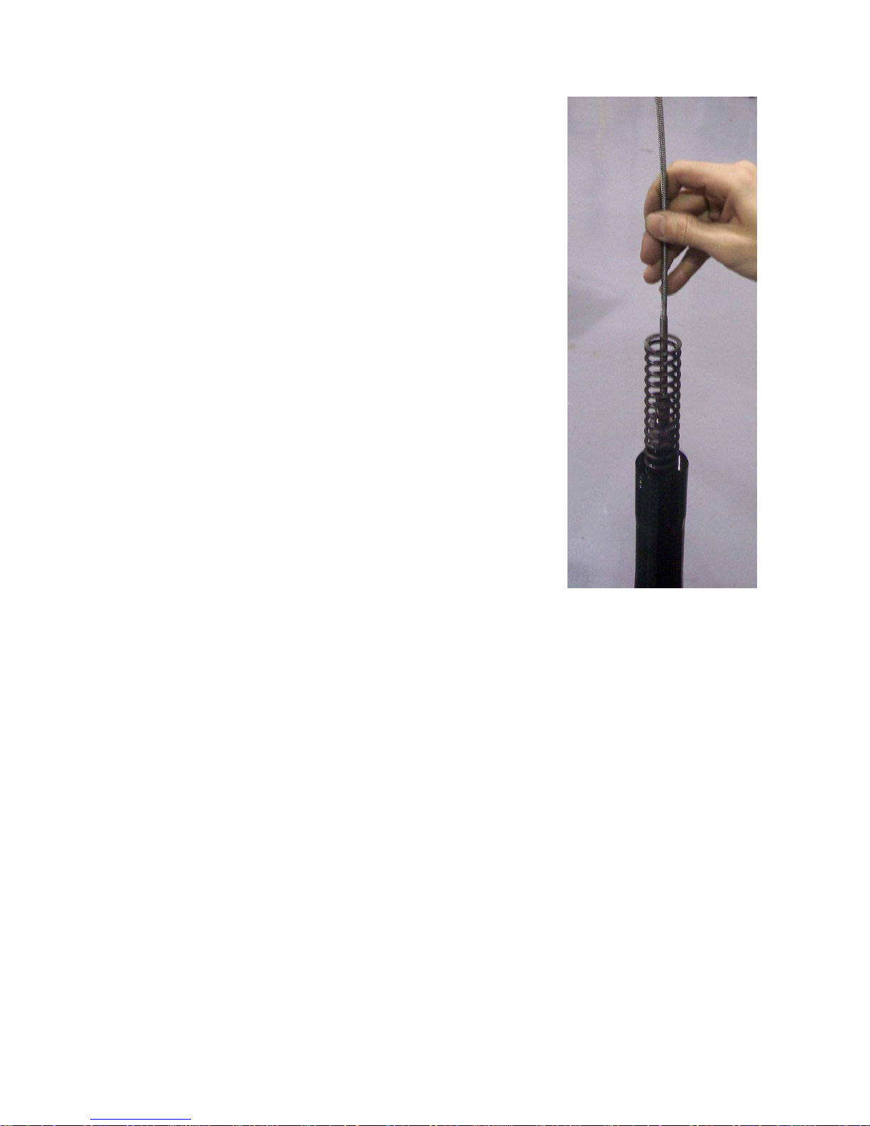
3. Install the fork spring.
4. Use a flexible retrieving tool to pull the damper rod up through the fork spring
(Figure 6.). Pull the fork spring down from the damper rod to expose the
damper rod lock nut. Secure this nut using a 19mm wrench.
5. Install the spacer and fork cap to the damper rod. Ensure that the fork cap is
completely threaded onto the damper rod before it makes contact with the
lock nut. Torque the damper rod lock nut to 15N-m (11ft-lb).
6. Install the fork cap to the fork tube. Torque the fork cap to 20Nm (15ft-lb).
7. Pump the fork leg several times to verify that it operates smoothly.
8. Install each leg back into the triple clamp. Torque each pinch bolt to 11N-m (8
ft-lb) making sure both legs are set to the same height in the clamps.
9. Install the front wheel, and torque the axle to 13.5N-m (10 ft-lb).
10. Drop the bike onto the ground, engage the front brake, and push up and
down on the handlebars several time to ensure that the front forks and the
front wheel are properly aligned with each other.
11. Tighten the axle pinch bolts to 10N-m (7.4 ft-lb).
Figure 6.
13
Parts
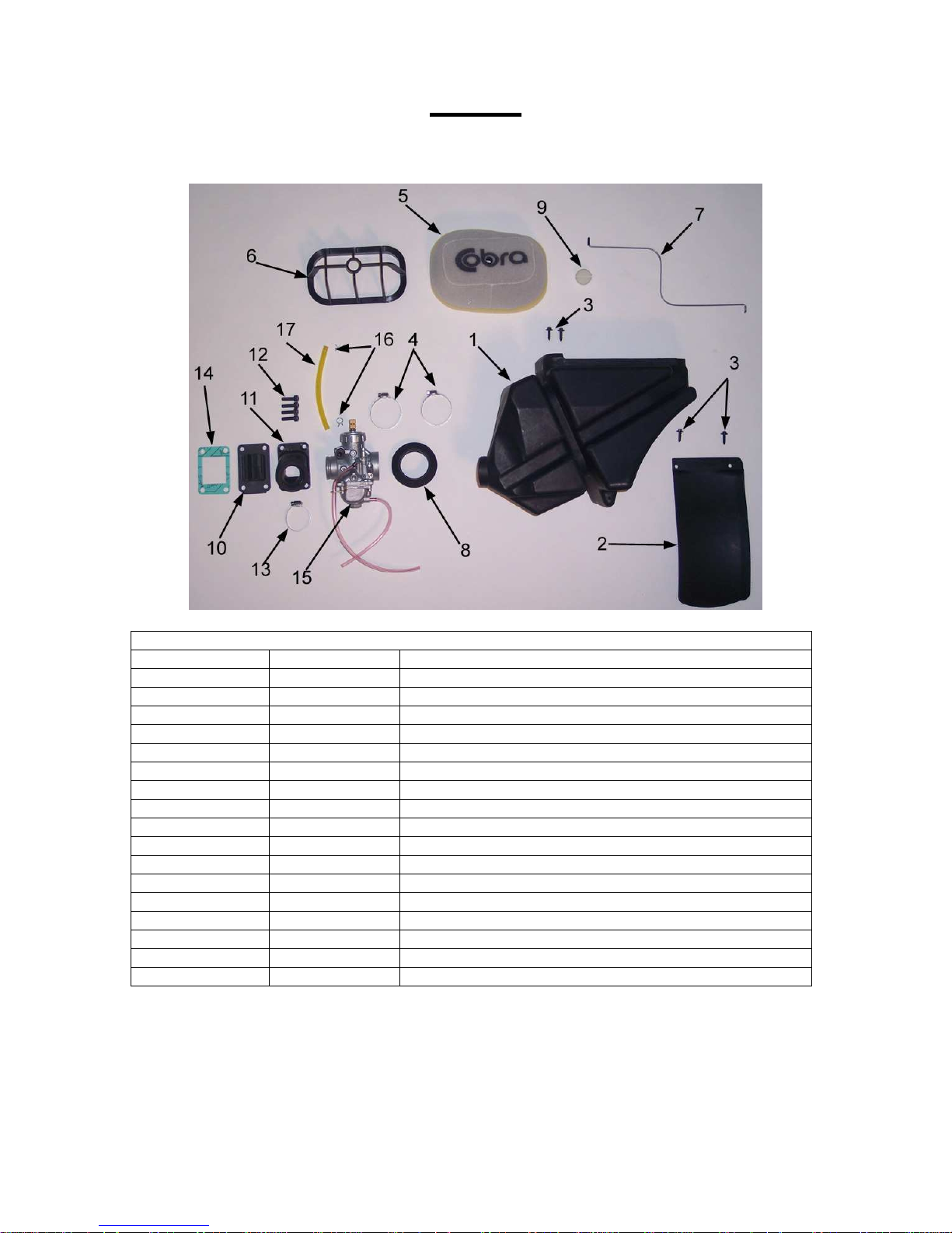
Parts – Airbox & Inlet System
Coolant System
REF # PART # DESCRIPTION
1 RCC60007 AIRBOX 07 65
2 TCC60008 MUD FLAP 07 65
3 HCSP0003 SCREW – PLASCREW
4 MCKGHO03 CLAMP, AIR BOOT TO AIR BOX
5 RCC60002 AIR FILTER 07 65
6 RCC60003 AIR FILTER CAGE
7 RCC60004 AIR FILTER WIRE 07 65
8 RCC60005 AIR BOOT, CARB TO AIRBOX 65
9 RCC60006 AIR FILTER CAP 07 65
10 ECC60006 REED ASSEMBLY 07 65
11 ECC60007 INLET MANIFOLD 07 65
12 HCBC0602 6X20MM SOCKET HEAD CAP SCREW
13 MCKGHO04 CLAMP, MANIFOLD TO CARB
14 ZCC60002 GASKET REED 07 65
15 RCC60001 CARBURETOR 24MM MIKUNI
16 MCMUCL04 HOSE CLAMP 8MM
17 FCMU0026 FUEL LINE
14
 Loading...