

Page 1

Owners
2006 P3-50
Parts
Service
Page 2
For parts orders contact your local dealer
To locate your closest Cobra dealer
log on to
www.cobramotorcycle.com
or call
(330) 549-9600
If you need technical assistance
contact your local dealer or call
the Cobra Technical Support Hotline at
(330) 549-9600
Cobra Motorcycle MFG., Inc.
11511 Springfield Road
North Lima, Ohio 44452
MCPW2006.2
1
Page 3

DISCLAIMER OF WARRANTY
This motorcycle is sold “as is” with all faults, obvious or not. There are no warranties
expressed or implied, including any warranty of merchantability and warranty of fitness
for any particular purpose.
“WARNING”
THE COBRA P3 IS A COMPETITION MODEL ONLY AND IS NOT MANUFACTURED
FOR, NOR SHOULD IT BE USED ON PUBLIC STREETS, ROADS OR HIGHWAYS.
THE USE OF THIS BIKE SHOULD BE LIMITED TO PARTICIPATION IN
SANCTIONED COMPETITION EVENTS UPON A CLOSED COURSE BY A
SUFFICIENTLY SKILLED RIDER AND SHOULD NOT BE USED FOR GENERAL
OFF-ROAD RECREATIONAL RIDING.
IMPROPER USE OF THIS MOTORCYCLE CAN CAUSE INJURY OR DEATH.
THIS BIKE IS INTENDED FOR EXPERIENCED RACERS ONLY AND NOT FOR
BEGINNERS.
IT IS YOUR RESPONSIBILITY AS THE OWNER OF THIS COBRA MOTORCYCLE
OR AS THE PARENT, OR LEGAL GUARDIAN OF THE OPERATOR, TO KEEP THIS
COBRA MOTORCYCLE IN PROPER OPERATING CONDITION.
THIS BIKE WAS DESIGNED FOR RIDERS THAT WEIGH LESS THAN 80 LBS WITH
FULL RIDING GEAR AND SHOULD NOT BE OPERATED BY RIDERS THAT WEIGH
MORE THAT.
BE SURE THAT THE RIDER ALWAYS WEARS ADEQUATE SAFETY GEAR
EVERYTIME HE OR SHE RIDES THEIR COBRA MOTORCYCLE.
IMPORTANT SAFETY NOTICE
Failure to follow WARNING instructions could result in severe injury or death to
the machine operator, a bystander, or a person inspecting or repairing the
machine.
CAUTION:
A CAUTION indicates special precautions that must be taken to avoid damage to
the machine.
NOTE:
A NOTE provides key information to make procedures easier or clearer.
2
Page 4

Table Of Contents
General Information.........................................................................................................5
Specifications - General..............................................................................................5
Specifications - Torque Values ..................................................................................6
Optional Components..................................................................................................7
Break-In Procedure......................................................................................................8
Starting Procedure.......................................................................................................9
General Tips ..................................................................................................................9
Maintenance....................................................................................................................11
Schedule & Tips .........................................................................................................11
Replacing Transmission / Clutch Lubricant............................................................12
Chain adjustment.......................................................................................................13
Front brake adjustment.............................................................................................14
Rear brake adjustment..............................................................................................15
Air Filter Cleaning.......................................................................................................15
Fork Oil Replacement................................................................................................16
Exhaust Power Regulator.........................................................................................17
Parts.................................................................................................................................18
Parts – Airbox and Inlet System I............................................................................18
Parts - Bars and Controls..........................................................................................20
Parts – Carburetor......................................................................................................21
Parts – Coolant System.............................................................................................22
Parts – Electrical System..........................................................................................23
Parts – Engine – Bottom End & Transmission......................................................24
Parts – Exhaust System............................................................................................29
Parts – Forks and Triple Clamps.............................................................................30
Parts – Frame – Mounting Hardware I....................................................................32
Parts – Front Brakes..................................................................................................35
Parts – Front Wheel...................................................................................................36
Parts – Oil Reservoir..................................................................................................37
Parts – Plastic Bodywork & Seat.............................................................................38
Parts – Rear Brake.....................................................................................................39
Parts – Rear Wheel....................................................................................................40
3
Page 5

Parts – Shock..............................................................................................................41
Parts – Swingarm Assembly.....................................................................................42
Service.............................................................................................................................43
Engine ..........................................................................................................................43
Clutch...........................................................................................................................43
Reeds...........................................................................................................................44
Carburetor...................................................................................................................46
Exhaust........................................................................................................................49
Rear wheel pullers .....................................................................................................49
Tuning ..............................................................................................................................50
Suspension..................................................................................................................50
Gearing ........................................................................................................................53
Carburetion..................................................................................................................54
Troubleshooting..............................................................................................................57
4
Page 6

General Information
Specifications - General
Items P3
Dimensions
Wheelbase 35.75” (908mm)
Wheel size 10” (254mm)
Seat height 22” (559 mm)
Engine
Type 2-stroke, single cylinder, reed valve
Cooling system Liquid-cooled
Displacement 49.8 cc
Bore and stroke 39 mm x 41.7 mm
Ignition system Digital Electronic
Spark plug Champion 8339-1, 8332-1 hotter, 8904-1 colder
Gap 0.023” – 0.025” (0.58 – 0.64 mm)
Fuel type high octane pump gasoline
Injector oil type Cobra Venom 2-cycle Race Oil
Fuel / oil mix ratios Fill oil reservoir as required
Ignition timing Fixed
Carburetion 12 mm Dell’Orto PHVA – PS
Main jet 82
RACE FUELS ARE NOT RECOMMENDED
Slow (Pilot) jet 42
Float height Non adjustable
Coolant Liquid Performance Mini Coolant / Antifreeze
Transmission
Speed Single
Clutch 3 shoe centrif ugal
Final drive ratio 10/44 T
Transmission / clutch oil type Cobra Venom 3 Shoe Clutch Milk
5
Quantity 250 ml (8.5oz)
Page 7
Chassis
Front tire 2.50 – 10
Pressure 20 psi minimum
Rear tire 2.50 – 10
Pressure 20 psi minimum
Front fork Marzocchi 32mm
Fork oil type SAE 20 weight
Fork oil amount 200 ml (6.8 oz) oil change, 220 ml (7.4 oz) rebuild
Fork oil height 70 mm (2.75”) collapsed from top with spring (no
spacer)
Specifications - Torque Values
Torque Value Fastener
Size &
ft-lb in-lb Nm
Cylinder head nuts 8.8 105 12 M6 X 1.0
Front engine mount bolts 22 264 30 M8 x 1.25
Rear engine mount bolts 22 264 30 M8 x 1.25
Swingarm pivot bolt 21 250 28 M14 x 2
Rear sprocket bolts 18 216 24 M7 x 1
Rear axle bolts 25 300 34 M12 x 1.25
Rear shock mounts 40 480 54 M10 x 1.5
Clutch adjust access plug 10 120 14 M12 x 1.25
Clutch nut 30 360 42
Units of mm unless otherwise specified
Remarks
6
Page 8

Optional Components
Call your dealer, or the factory, for details
• Carburetor jets
o Main jets #’s 74, 76, 78, 80, 84, 86, 88, 90, 92, 94
o Slow jets #’s 38, 40, 42, 45,
• Exhaust Power Regulator, ECPW0001
• Pre-filter for Airbox
• Sprockets
o Front sprocket, 11T
o Rear sprocket, 39 T – 45 T
• Suspension Springs
Weight of Rider (lb) Fork Spring Shock Spring
Less than 38 (light) KCMZ0012A
(12 lb/in, 2.10 N/mm)
38 – 45 (std) KCMZ0012
(14 lb/in, 2.45 N/mm)
46 to 55 (stiff) KCMZ0012B
(16 lb/in, 2.80 N/mm)
• Suspension Valving
Damping Rate Fork Valving
Compression
(right)
Soft (fast) KCMZ0033A KCMZ0032A SCMU0318A
Standard KCMZ0033 KCMZ0032 SCMU0318
Hard (slow) KCMZ0033B KCMZ0032B SCMU0318B
• Tires
• Tubes or ‘Tire Balls’
Fork Valving
Rebound
(left)
SCMUOH04
(red) 275 lb/in
SCMUOH05
(yellow) 285 lb/in
SCMUOH06
(white) 295 lb/in
Shock Valving
(kit)
7
Page 9

Break-In Procedure
Your Cobra P3 is a close-tolerance high performance machine and break-in time
is very important for maximum life and performance. The P3 can be ridden hard
after the first ½ hour break-in time but it is recommended that no adjustments are
made to the carburetion or suspension until the full 8 hours of bike break-in has
elapsed. Also, after the engine, transmission, and drive train have been broken-in
for the full 8 hours, the bike will be faster!
Fill the fuel tank with high octane pump gas without oil. Also, fill the oil injection
reservoir with Cobra’s specially formulated Cobra Venom 2-cycle Race Oil. (Part
# MCMUOL02)
CAUTION:
Failure to use proper fuel or oil may result in premature engine wear, or damage
to the machine.
Adhering to the following break-in schedule will result in long lasting high
performance machine.
• Start bike on stand
• First 5 minute period, operate the bike on the stand with a combination of idle
and high RPM operation. (avoid prolon ged high RPM but spin the rear
wheel good at least once or twice per minute)
• Allow bike to cool
• Ride for 15 minutes maximum (avoid prolonged high RPM operation and
avoid abusing the clutch with throttle blipping.
• Cool and inspect bike for loose fasteners.
• Next ½ hour of operation, avoid prolonged operation at Wide Open Throttle.
• After 1 hour of operation
o Check for loose bolts and nuts on the bike and retighten as
necessary (proper toque values are listed under Specifications).
o Clean the carburetor bowl.
o Change the transmission / clutch lubricant.
• After 8 hours of operation
o Change the fork oil.
o Have a Certified Cobra Mechanic change the shock oil.
• Your bike is now ready for the highest level of competition!
8
Page 10

Starting Procedure
Before starting the machine inspect the following:
• Make sure vehicle is properly maintained (see Schedule & Tips in the
Maintenance section)
• Fill the 2-stroke injector oil reservoir with Cobra’s specially formulated Cobra
Venom 2-cycle Race Oil.
• Insure that the fuel tank contains an adequate volume of fuel to complete
the distance required. (high octane pump gas).
• Check the throttle for smooth operation and sound closing.
• Turn the fuel on by rotating the fuel petcock knob to the vertically downward
position (reserve position is horizontally forward).
CAUTION:
For best results from your Cobra Motorcycle use only the recommended fuels.
Testing has shown that most ‘race’ fuels actually degrade performance.
When your pre-ride inspection is complete the bike may be started. For a cold
engine follow this procedure.
1. Place the motorcycle on a stand of sufficient strength that positions the
motorcycle in a level upright position with the rear wheel off the ground.
2. On the carburetor, flip the black choke knob upward from the right side of
the bike.
3. Kick start the engine by kicking the lever forward.
4. Rev the engine in short spurts, turning the throttle no more than 1/4 open
until the engine will run without the choke.
5. Verify a functional engine shut-off switch by shutting off the engine.
6. Restart the engine and proceed with riding when the engine is sufficiently
warm (i.e. the side of the cylinder is warm to touch).
CAUTION:
Never rev an engine full throttle when it’s cold or slightly warmed up. Cobra
recommends that you tell your child to take it easy the first couple of minutes in
practice until the engine comes up to full operating temperature. Make sure your
engine is properly warmed up before racing.
This is a high performance race motorcycle. Too much application of throttle will
likely land your little racer on his or her arse. Fenders can be replaced but
bruised egos and other body parts take longer.
General Tips
1. Always wear a helmet and other protective riding gear.
9
Page 11

2. Cobra recommends that you tell your child to take it easy the first couple of
minutes in practice until the engine comes up to full operating temperature.
3. Make sure your riders’ foot is not resting on the foot brake while they are
riding.
4. Evaluate the bikes jetting only after it has been warmed up to race
temperatures.
5. A properly maintained machine is safer, faster, and more fun to ride.
6. Cobra offers a carburetor inlet cover RCMU0109 to keep water and dirt
from getting into the carburetor when the bike is being washed.
7. It is acceptable and common to run 40:1, or leaner, premix in the fuel tank.
8. New chains will stretch on first use. Never install a new chain prior to a
race. Always ‘break’ them in during practice.
9. I f your young rider is initially uncomfortable with the abrupt power delivery
of the P3, install the Exhaust Power Regulator to make the bike more
easy to control while your rider gains confidence with his or her abilities and
the feel of the new machine.
10. Your Cobra Motorcycle has a 10 digit VIN (Vehicle Identification Number).
The first two digits indicate the model and the seventh indicates the model
year (MY).
a. Example, Oixxxx6xxx is a 2006 Model Year Oil Injected P3.
10
Page 12

Maintenance
Schedule & Tips
It is important that you adhere to this maintenance schedule so as to promote the
longevity of your Cobra Motorcycle.
• Between each ride
o Fill the 2-stroke injector oil reservoir.
o Check the air filter (clean and re-oil as necessary).
o Insure the smooth operation of the throttle cable (throttle soundly
‘clacks’ shut).
o Check for frayed strands of the throttle cable inside the throttle housing
and replace if necessary.
o Check for adequate tire pressures and adjust if necessary.
o Check all nuts and bolts for proper torque and re-torque if necessary.
o Spray all moving parts with WD40 or other light oil.
o Check drive chain for
§ Proper tension and adjust if necessary.
§ Adequate lubrication and lubricate if necessary.
o Insure that the ignition stator and rotor are clean and dry.
o Check the frame for cracks in the metal or cracks in the paint that
might indicate that the metal has been stressed beyond it’s safe limits.
Replace or get properly rewelded as necessary.
o Fill the 2-stroke injector oil reservoir with Cobra’s specially formulated
Cobra Venom 2-cycle Race Oil.
• Every 2 hours of operation
o Replace the transmission oil.
• Every 10 hours of operation
o Replace the fork oil.
o Have the shock oil replaced by a Certified Cobra Mechanic.
CAUTION:
1. If y ou ever need to weld anything on the bike, disconnect the spark plug
cap, unplug the ignition, disconnect the kill switch, scrape the paint bare
near the area to be welded and put the ground clamp as close to the area
to be welded as possible.
11
Page 13
Be sure the fuel tank and carburetor have been removed and safely located
away from the welding process.
2. The frame is 4130 Chrome Moly and it is important to weld it with the proper
rod and heat settings set as light as possible. Cobra recommends replacing
the frame with a new one if the old one becomes damaged.
Replacing Transmission / Clutch Lubricant
Tools needed:
• 250 ml (8.5oz) Cobra Venom 3 Shoe Clutch Milk (Part # MCMUGF01)
• #3 Phillips screwdriver
• large flat blade screwdriver or coin
Procedure:
1. Begin this procedure with a bike that has been ridden more than 5 minutes
but less than 10 minutes. It is desired to have the engine warm enough so
that the oil is ‘runny’ but not so hot that there is risk of being burned by the
engine or the oil.
Hot oil and hot components on the motorcycle may cause burns.
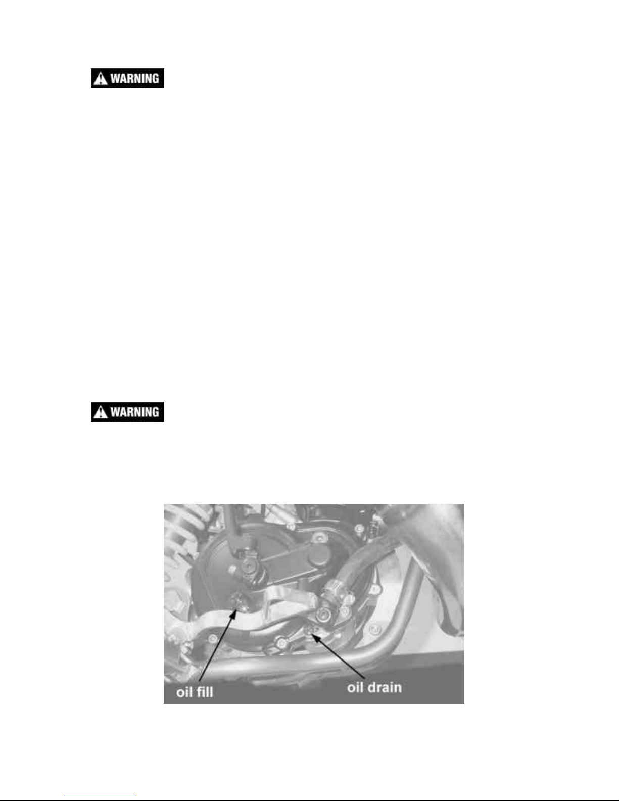
2. Lean bike against something or set on stand with oil drain hole.
3. Using Phillips screwdriver, remove the oil drain bolt located on the right side
of the engine (figure 1).
Figure 1
12
Page 14
NOTE: You may need to adjust the brake pedal (up or down) to gain access to
the drain bolt.
4. After it has drained, reinstall the drain screw with gasket.
5. Refill oil from oil fill plug 250 ml (8.5oz) Cobra Venom 3 Shoe Clutch Milk
(Part # MCMUGF01) thru the fill plug.
NOTE: Leaning the bike over onto it’s left hand side will facilitate the oil filling
procedure.
6. Reapply the oil fill screw, securely, being sure the gasket is in place.
CAUTION:
Cobra has spent considerable time and money developing the proper lubrication
to handle the harsh environment of the automatic clutch and transmission of this
motorcycle. Cobra was forced to put forth this effort because the other available
options and not adequate. Cobra’s specially developed Cobra Venom 3 Shoe
Clutch Milk (Part # MCMUGF01) is the recommended lubricant for your P3
motorcycle.
Chain adjustment
Tools required for chain adjustment
• 19 mm wrench or socket
• 13 mm wren ch or socket
1. Make sure that the rear
wheel is aligned
properly.
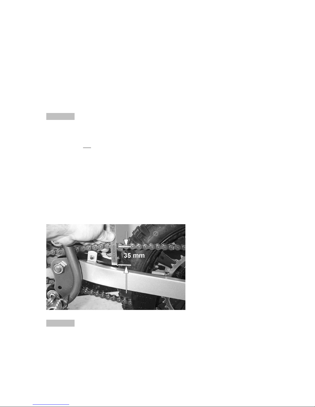
2. For proper adjustment,
the chain should have 35
mm (1 3/8”) free
movement just behind
the chain block with no
load on the bike (figure
2)
Figure 2
CAUTION:
Sit on the bike and verify that the chain has a minimum of 12mm (1/2”) free
movement when the chain is at it’s tightest point.
13
Page 15
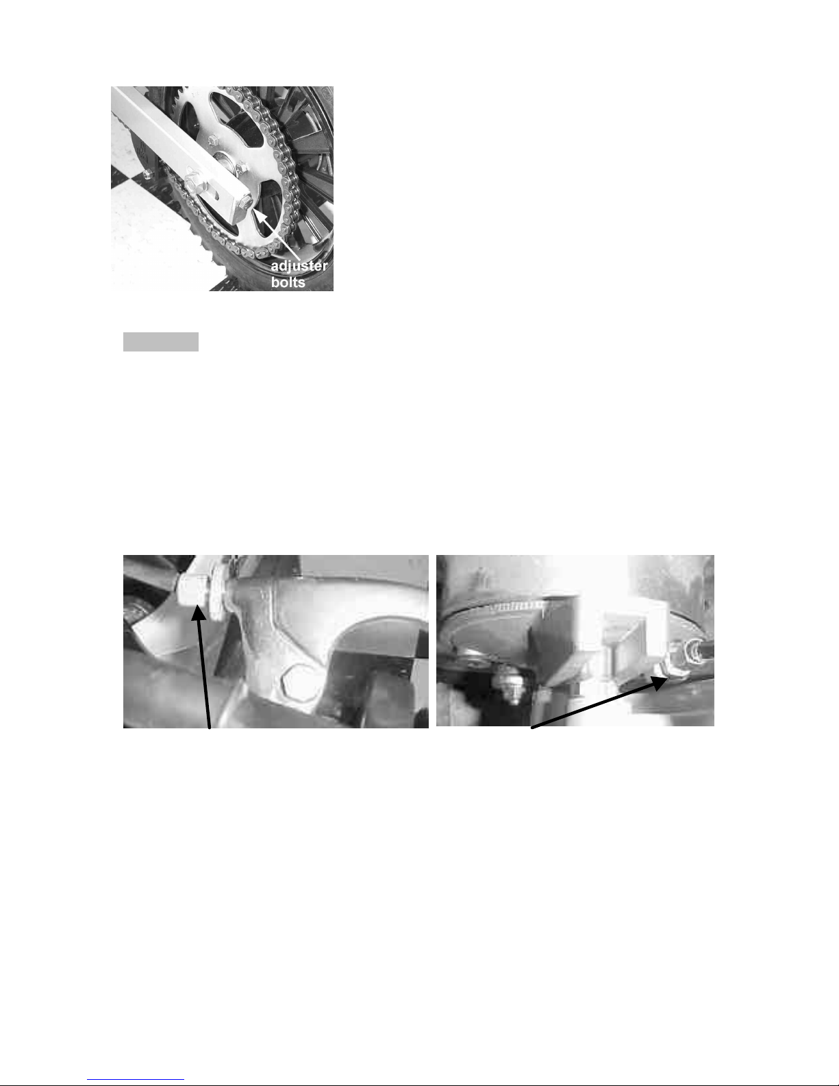
3. If the chain requires adjusting, loosen the axle
with a 19 mm wrench and tighten the chain by
rotating the adjustor bolts clockwise (CW) or
loosen the chain by rotating the adjustor bolts
(CCW).
4. Retighten the axel bolt to 25 ft-lb (34 Nm).
5. Retighten the adjustor bolt
Figure 3
CAUTION:
Always check rear brake adjustment and free-play after adjusting the chain.
NOTE:
Lubricate the chain with a light weight oil like Liquid Performance Chain Lube, or
WD40 to reduce frictional drag.
Front brake adjustment
Tools recommended for front brake maintenance:
• 10mm open end wrench
Figure 4, from the brak e lever Figure 5, from the brake hub
From the brake lever:
1. Slide the cover out of the way
2. Loosen the locking nut on the brake lever.
3. Adjust the bolt to desirable position.
4. Tighten the locking nut.
5. Slide the protective cover back over the lever pivot and adjustor
From the brake hub:
1. Loosen the 10mm nut on the hub.
2. Adjust the brake cable to desirable position
3. Tighten the 10mm nut.
14
Page 16
CAUTION:
If you tighten the front brake up too much, the brakes may hang up causing the
brake pads to wear incorrectly and prematurely.
Rear brake adjustment
Tools recommended for rear brake maintenance:
• 10mm open end wrench
There are 2 adjustments on the brake.
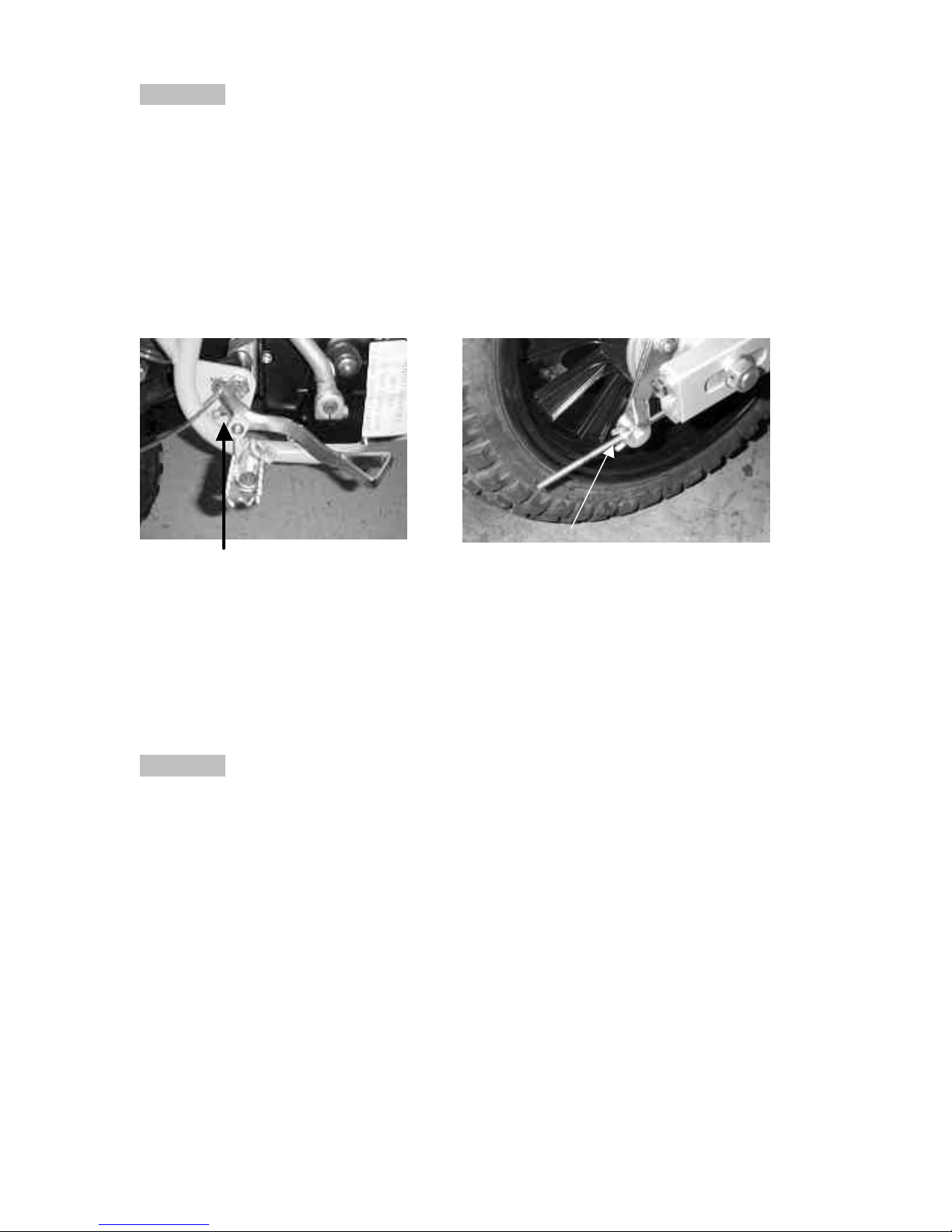
Figure 6, adjust brake lever free height Figure 7, adjust lever ‘free play’
From the brake lever:
6. Loosen the 10mm nut on the back of the brake pedal.
7. Adjust the bolt to desirable position
8. Tighten the 10mm nut.
From the brake hub:
1. Adjust the wing nut to the desirable position.
CAUTION:
If you tighten the wing nut too much, the brakes may remain engaged. If so, the
brake pads will burn up, and need replaced.
Air Filter Cleaning
Tools recommended for air filter maintenance:
• #2 Phillips head screwdriver
• 4 mm hex key (Allen)
• Foam filter oil
Procedure
1. Removed the seat with the 4 mm hex key
2. Remove the filter/air inlet boot from the back of the carburetor with a flat
screwdriver
3. Pull the filter / boot assembly back, up, and out the top of the airbox.
15
Page 17
4. Clean the filter in a nonflammable solvent to remov e the filter oil.
Do not clean the air filter with gasoline or other highly volatile petroleum product.
Diesel fuel or kerosene would be preferred but caution should still be taken. Hot
soapy water works well.
5. Clean the filter in hot soapy water to remove all dirt particles.
6. Allow it to dry thoroughly.
7. Saturate with filter oil and remove excess.
NOTE:
The Cobra is equipped with a special designed Air box. It is very important to
keep the air filter clean and properly oiled with high quality water-resistant foam
filter oil. It’s very important to oil your filter consistently each time because varied
amounts of oil will change your carburetor jetting.
8. Reinstall the filter / boot assembly by pushing it down and forward into the
airbox making sure the letters “PW” are visible between the carburetor and
airbox (figure 8).
Figure 8
NOTE:
Make sure you change or clean your filter after each moto. We recommend
carrying multiple filters in your toolbox, one for each practice session and moto.
Fork Oil Replacement
Tools required
• 5 & 6 mm Allen wrench
16
Page 18
• 19 mm wrench or socket (two required)
• Spring clip remover
Disassembly
1. Remove the front wheel.
2. Remove the fork legs from the triple clamps.
3. Perform the following on one leg at a time.
4. Using your hands, remove the black rubber plug from the top of the fork leg
exposing the white plastic cap.
5. Secure the fork leg assembly in a vice by gripping the leg across the flats
through which the axle bolt goes through.
6. Depress the white plastic cap inwards (down) and remove the wire spring clip
from its groove.
7. Remove the white cap, the fork spring preload sleeve, and the fork spring.
NOTE: Depressing the fork leg will facilitate removing the white cap.
8. The fork can now be turned upside down and drained.
Assembly
1. Fill the leg with 200 cc (6.8 oz) 20 wt fork oil.
2. Standard fork oil level is 70 mm (2.75”) from the top edge with the fork
collapsed.
NOTE: Remove the preload sleeve but leave the spring in for the measurement.
3. Install the preload sleeve.
4. Install and depress the white cap while installing the spring clip.
5. Fork may be reinstalled.
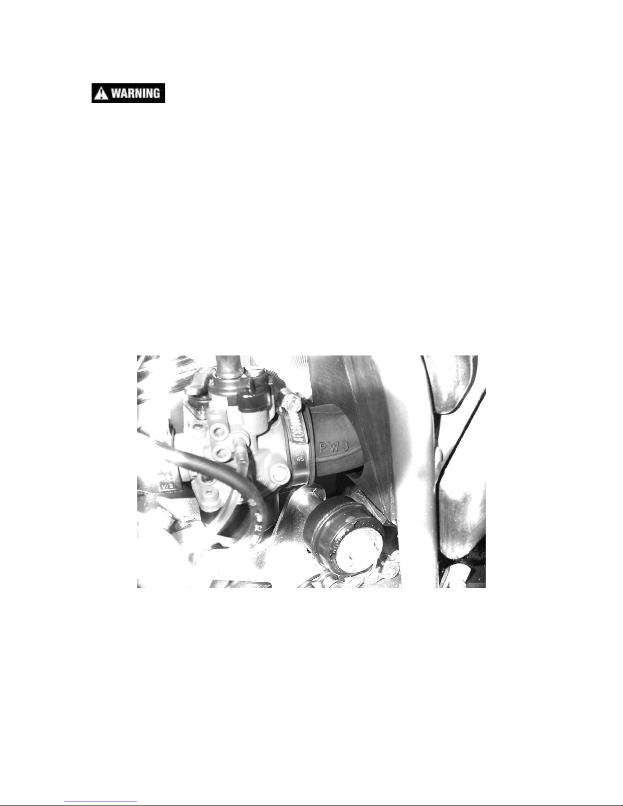
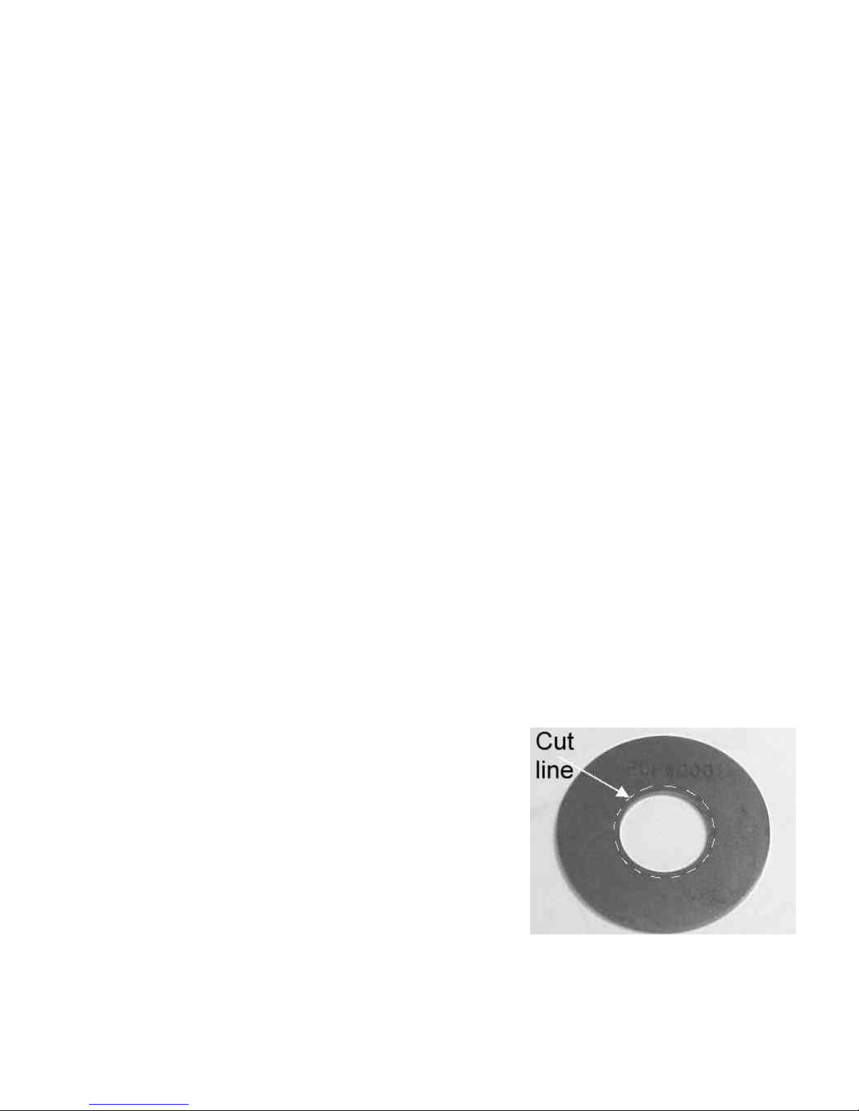
Exhaust Power Regulator
As an entry level race machine, the Cobra P3
comes with an optional Exhaust Power Regulator
(EPR) (figure 9b) that when installed, between the
exhaust pipe and cylinder flange, will cut the peak
rear wheel power by ½. As your rider’s skills
progress, the EPR can be opened up to the etched
line (18mm diameter drill) to deliver ¾ power or
removed it completely for full race power.
Figure 9b
17
Page 19

Parts
Parts – Airbox and Inlet System I
FIGURE 10
Airbox and Inlet System
REF # PART # DESCRIPTION
1 RCMU0404 AIR BOX – P3
2 RCMU0408 MUD FLA P – P3
3 RCMU1407 BRACKET – MUD FLAP
4 HCBB0612 M6X12 BUTTON HEAD BOLT (2 REQ’D)
5 RCMU0409 CHAIN GUARD
6 HCFH0612 M6 X 12 FLAT HEAD SCREW
7 HCFH0620 M6 X 20 FLAT HEAD SCREW
8 HCNL0601 6MM LOCK NUT
9 RCMU0403 AIR FILTER WITH BOOT
10 ECMPIN01 CARBURETOR 12 MM (OIL INJECTED)
Not Shown FCMU0026 FUEL LINE
Not Shown MCMUCL04 HOSE CLAMPS – FUEL LINE
11 MCKGHO01 HOSE CLAMP – AIR BOOT TO CARBURETOR
12 ECMOIN02 HOSE CLAMP – CARBURETOR TO MANIFOLD
13 FCPW0002 THROTTLE CABLE
18
Page 20

Parts – Airbox and Inlet System II
Figure 11
REF NO PART NO DESCRIPTION
1 ECMPIN01 12MM CARBURETOR
Not Shown FCMU0026 FUEL LINE
Not Shown MCMUCL04 HOSE CLAMPS – FUEL LINE
2 ECMOIN02 CLAMP
3 HCBC0625 6X25 CAP SCREW
4 ECMOIN04 REED SPACER PLATE
5 ZCMOIN05 REED VALVE GASKET
6 ECMOIN06 REED VALVE ASSEMBLY
NOT SHOWN ECMOIN07 REED PEDALS
8 ECMOIN08 SCREW – REED CAGE TO SPACER PLATE
9 ECMOIN09 RUBBER INTAKE BOOT
10 ECMOIN10 INTAKE RETAINING PLATE
19
Page 21

Parts – Bars and Controls
Figure 12
Bars and Controls
REF # PART # DESCRIPTION
1 FCPW0001 THROTTLE ASSEMBLY
3 TCMU0008 GRIPS (SET OF TWO)
4 FCPW0002 THROTTLE CABLE
5 FCMU0033 KILL SWITCH ASSEMBLY
6 KCMZ0001 M8X50 SOCKET HEAD CAP SCREW (4 REQ’D)
7 KCMZ0003 LOWER HANDLE BAR CLAMP (2 REQ’D)
8 KCMZ0002 TOP HANDLE BAR CLAMP (2 REQ’D)
9 TCMU0019 HANDLEBAR – ALUMINUM
11 BCMU0100 BRAKE LEVER / PERCH ASSEMBLY WITH ADJUSTOR
13 BCMU0108 FRONT BRAKE CABLE
14 BCMU0013 BRAKE LEVER COVER
Not shown FCPW0004 THROTTLE CABLE END GROMMET
20
Page 22

Parts – Carburetor
REF
PART #
DESCRIPTION
Figure 13
1 RCOI0001 SLIDE – 40 – STOCK
1 RCOI0030 SLIDE – 30
1 RCOI0050 SLIDE – 50
2 RCOI0002 NEEDLE FOR SLIDE
3 RCOI0003 ATOMIZER
4 RCOI0004 MAIN JET-82 STOCK
RCOI00## ADDITIONAL MAIN JETS, 74 – 94
EXAMPLE RCOI0094 FOR 94 MAIN
5 RCOI0005 PILOT JET-42 STOCK
RCOI00## ADDITIONAL PILOT JETS, 38 – 45
EXAMPLE RCOI0045 FOR 45 PILOT
6 RCOI0006 CHOKE JET
7 RCOI0007 TOP CARB SCREW
8 RCOI0008 O-RING FOR CARB TOP
9 RCOI0009 CARB TOP W/ O-RING
10 RCOI0010 SLIDE SPRING
11 RCOI0011 NEEDLE RETAINER PLATE
12 RCOI0012 NEEDLE CLIP
13 RCOI0013 IDLE ADJUSTMENT SCREW
14 RCOI0014 IDLE ADJUSTMENT SPRING
16 RCOI0016 FUEL MIXTURE SCREW KIT-4 PIECE
17 RCOI0017 FLOAT KIT – 3 PIECES
19 RCOI0019 FLOAT BOWL WITH O-RING – 2 PC
20 RCOI0020 BOTTOM CARB SCREW
22 RCOI0022 CHOKE ASSEMBLY – 4 PIECES
23 RCOI0023 REBUILD KIT
Not
Shown
Not
Shown
FCMU0026 FUEL LINE
MCMUCL04 HOSE CLAMPS – FUEL LINE
21
Page 23

Parts – Coolant System
Figure 14
Coolant System
REF # PART # DESCRIPTION
1 ECMU0061 RADIATOR WITH CAP
2 ECPW0002 RADIATOR HOSE LEFT
3 MCMUCL07 HOSE CLAMP STANDARD (three places)
4 ECHA0003 MOUNTING BRACKET – RADIATOR BOTTOM
5 HCBC0607 M6X50 SOCKET HEAD CAP SCREW
6 HCNL0601 6MM LOCK NUT
7 MCKGGR00 GROMMET – RADIATOR MOUNTING
8 ECPW0003 RADIATOR HOSE RIGHT
10 ECHA0002 VENT HOSE
11 ECHA0109 MOUNTING BRACKET – RADIATOR TOP
12 HCBC0660 M6X60 SOCKET HEAD CAP SCREW
13 MCMUCL11 HOSE CLAMP LARGE (one place)
22
Page 24

Parts – Electrical System
Figure 15
Electrical System
REF # PART # DESCRIPTION
1 ECMOIG06 CDI UNIT
2 HCBF0616 M6X16 FLANGE HEAD BOLT
3
4 ECMOIG01 STATOR & FLYWHEEL
5 HCBC0401 M4X18 SOCKET HEAD CAP SCREW
6 ECMOIG16 SPACER – FLYWHEEL
8 HCWF0801 8MM FLAT WASHER
9 HCNS0801 8MM NUT
10 FCMU0033 IGNITION CUT-OFF SWITCH ASSEMBLY
NOT SHOWN
MCOIWC01 WIRE CONNECTOR – MALE TO MALE PLUG
11 ECMOIG05 IGNITION COIL WITH SPARK PLUG CAP
12 HCBC0602 M6X20 SOCKET HEAD CAP SCREW
13 HCNL0601 6MM LOCKNUT
14 ECOI0110 COIL BRACKET – LEFT HAND SIDE
15 ECOI0111 COIL BRACKET – RIGHT HAND SIDE
16 HCBC0804 M8X80 SOCKET HEAD CAP SCREW
17 HCNL0801 8MM LOCKNUT
18 ECMU0065 SPARK PLUG, CHAMPION (8339-1)
18H ECMU0067 OPTIONAL HOTTER PLUG (8332-1)
18C ECMU0066 OPTIONAL COLDER PLUG (8904-1)
23
Page 25

Parts – Engine – Bottom End & Transmission
Figure 16
REF NO PART NO DESCRIPTION
1 ECMOBE01 CASES – COMPLETE SET
2 ECMOBE02 OUTPUT BEARING
3 ECMOBE03 OUTPUT BEARING – SNAP RING
4 ECMOBE04 PRECISION BEARING
5 ECMOBE05 CRANK SEAL
6 ECMU0016 CRANK BEARING
7 ECMOBE07 CRANKSHAFT COMPLETE
8 ECMOBE08 FLYWHEEL KEY
9 ECMU0077 WRIST PIN BEARING
10 HCBC0660 6X60 CAP SCREW
11 HCBC0607 6X50 CAP SCREW
12 ZCMOBE12 CRANKCASE GASKET
13 ECMOBE13 OUTPUT SEAL
14 ECMOBE14 ROD WITH WRIST PIN AND BEARING
15 S6 V/EC.+COM. SET OF SEAL
16 ZKMOBE16 GASKET KIT
17 ECMOBE17 DOWEL PIN – CASE
18 ECMOBE18 CASE VENT PIPE
24
Page 26

Parts – Engine – Clutch
Figure 17 Clutch components
REF NO PART NO DESCRIPTION
1 ECMOCL01 GEAR – DRIVE
3 ECMOCL03 CLUTCH START NUT – LH THREAD
4 ECMOCL04 WASHER – CLUTCH NUT BACK UP
5 ECMOCL30 CLUTCH COMPLETE
6 ECMOCL06 SPACER – CLUTCH TO HUB
7 ECMOCL07 BUSHING – CLUTCH HUB
9 ECMOCL09 WASHER – CLUTCH BASKET BACK UP
10 PCMOCL10 SPROCKET – 10 TOOTH
11 ECMOCL11 SNAP RING – OUTPUT SHAFT
12 ECMOCL12 CLUTCH BASKET WITH GEAR
13 HCBS0004 CLUTCH BOLT
14 ECMOCL35 CLUTCH SHOE
15 ECMOCL36 BELLVILLE SPRING WASHER
16 ECMOCL34 SHIM 0.2MM
17 ECMOCL33 SHIM 0.5MM
18 ECMOCL37 CLUTCH ARBOR
25
Page 27

Parts – Engine – Ignition Side
Figure 18
REF NO PART NO DESCRIPTION
1 ECMOWP01 WATER PUMP SHAFT
2 ECMOWP02 RETAINER CLIP – WATER PUMP BEARING
3 ECMOWP03 BEARING WATER PUMP
4 ECMOWP04 SPACER – WATER PUMP BEARING
5 ECMOWP05 CRANK PULLEY
6 ECMOWP06 WATER PUMP BELT
7 ECMPWP07 CLAMP FOR OIL TUBE
8 HCBC0501 5X12 CAP SCREW
9 ECMPWP09 OIL INJECTOR MOUNT PLATE
10 ECMPWP10 OIL PUMP WITH TUBE
11 ECMOWP11 WATER PUMP IMPELLER
12 ECMOWP12 SNAP RING – TOOTHED
13 ECMOWP13 WATER PUMP SEAL
14 ECMOWP14 WASHER – BEARING RETAINER
15 ECMPWP15 DOWEL PIN
16 HCWF0501 5MM WASHER
17 ECMOIG01 FLYWHEEL AND STATOR
18 HCWF0801 8MM FLAT WASHER
19 HCNS0801 8MM NUT
20 HCBC0401 M4X18 SOCKET HEAD CAP SCREW
21 ECMOIG16 SPACER – FLYWHEEL
22 ECMOIG20 GROMMET – FLYWHEEL
23 ECMOIG18 COVER – IGNITION
24 HCBC0550 M5X50 SOCKET HEAD CAP SCREW (3 REQ’D)
25 HCWF0501 5MM FLAT WASHER (4 REQ’D)
26 ECMOIG13 7MM DOWEL
27 HCBC0502 M5X20 SOCKET HEAD CAP SCREW (1 REQ’D)
28 ECMOIG15 GROMMET – IGNITION COVER – CLOSED
29 ECMOIG14 GROMMET – IGNITION COVER – OPEN
26
Page 28

Parts – Engine – Kick Starter
Figure 19
REF NO PART NO DESCRIPTION
1 ECMOKS01 CLUTCH COVER
2 ECMOKS02 CRUSH WASHER – WATER DRAIN PLUG
3 ECMOKS03 WATER DRAIN PLUG – 6X8
4 ZCMU0001 OIL FILL PLUG GASKET
5 ECMU0037 OIL FILL PLUG
6 ECMOKS06 RETAINER CLIP – THRUST WASHER
8 HCBC0625 6X25 CAP SCREW
9 ECMPKS09 KICK START LEVER
11 HCBC0603 6X30 CAP SCREW
12 ZCMOKS12 CLUTCH COVER GASKET
13 ECMOKS13 THRUST WASHER
14 ECMOKS14 SEAL – KICK START SHAFT
15 ECMOKS15 KICK START SHAFT WITH GEAR
16 ECMOKS16 KICK START SPRING
17 ECMOKS17 WASHER – RETURN SPRING RETAINER
18 ECMOKS18 RETAINER CLIP – RETURN SPRING
19 ECMOKS19 J-SPRING KICK START
20 ECMOKS20 DOG GEAR
21 ECMOKS21 GASKET – ADJUSTING PLUG
22 ECMOKS22 ADJUSTING PLUG
NOT SHOWN ECMOKS03
OIL DRAIN PLUG
27
Page 29

Parts – Engine – Top End
Figure 20
REF NO PART NO DESCRIPTION
1 ECMOTE01 CYLINDER - CHROME
2 ECMOTE02 PISTON KIT - SINGLE RING
3 HCBC0603 6X30 CAP SCREW
4 HCNF0601 FLANGED NUT 6MM
5 ECMOTE05 CYLINDER HEAD
6 ZCMOTE06 CYLINDER HEAD O-RING
7 ECMU0026 6MM DOWEL
9 ECMOTE09 CYLINDER HEAD STUD BOLT 6MM
10 ZCMOTE10 BASE GASKET
11 ZCMOTE11 O-RING - EXHAUST FLANGE
12 ECMU0056 PISTON RING - CAST
13 ECMU0076 WRIST PIN
14 ECMUSR04 SNAP RING-FRANCO PISTON
28
Page 30

Parts – Exhaust System
Figure 21
Exhaust System
REF # PART # DESCRIPTION
1 XCPW2004 P3 EXHA UST PIPE
2 ZCMOTE11 O-RING – EXHAUST (2 REQ’D)
3 XCMU0005 SPRING – EXHAUST SHORT
4 XCMU0028 PIPE / SILENCER SEAL
5 XCKG0003 SILENCER
NOT SHOWN XCMU0018 SILENCER PACKING
6 MCMUGR04 GROMMET – SILENCER MOUNTING (2 REQ’D)
7 HCBF0630 M6X30 FLANGE HEAD BOLT
8 MCMUGR06 PIPE GROMMET MALE
9 MCMUGR07 PIPE GROMMET FEMALE
10 MCMUSP02 PIPE GROMMET SPACER
11 HCWF1478 PIPE GROMMET WASHER
12 HCBF0635 M6X35 FLANGE HEAD BOLT
13 ECPW0001 Exhaust Power Regulator
29
Page 31

Parts – Forks and Triple Clamps
Figure 22
Front Forks and Triple Clamp
REF # PART # DESCRIPTION
1 KCMZ0029 OUTER FORK LEG – RIGHT (NON BRAKE) SIDE
NOT SHOWN KCMZ0031 OUTER FORK LEG ASSY – RIGHT WITH SEAL & SWIPER
NOT SHOWN KAPW005R FORK LEG COMPLETE – RIGHT SIDE
2 KCMZ0020 OUTER FORK LEG – LEFT (BRAKE) SIDE
NOT SHOWN KCMZ0021 OUTER FORK LEG ASSY – LEFT WITH SEAL & SWIPER
NOT SHOWN KAPW005L FORK LEG COMPLETE - LEFT SIDE
3 KCMZ0026 INNER FORK LEG – RIGHT (COMPRESSION) SIDE
4 KCMZ0027 INNER FORK LEG – LEFT (REBOUND) SIDE
5 HCCC0001 CLAMP – BRAKE CABLE
6 HCBC0502 M5X20 SOCKET HEAD CAP SCREW
7 HCNL0501 5MM LOCK NUT
8 HCBF0616 FENDER BOLT, M6X16 FLANGE HEAD (4 REQ’D)
9 KCMZ0025 TRIPLE CLAMP – LOWER WITH STEM
10 HCBC0625 M6X25 SOCKET HEAD CAP SCREW (4 REQ’D)
11 KCMZ0005 TRIPLE CLAMP – UPPER (NO BAR MOUNTS)
12 HCBC0806 M8X30 SOCKET HEAD CAP SCREW (2 REQ’D)
13 KCMZ0003 BAR MOUNT – LOWER (2 REQ’D)
14 KCMZ0002 BAR MOUNT – UPPER (2 REQ’D)
15 KCMZ0001 M8X50 SOCKET HEAD CAP SCREW
16 HCNJ0101 STEERING HEAD NUT 1X1 4
17 FCMU0004 STEERING HEAD BEARING (2 REQ’D)
18 FCMU0103 DUST COVER (2 REQ’D)
19 BCMU0007 BRAKE STOP
20 HCBH0808 M8X30 BUTTON HEAD SCREW
30
Page 32

Parts –
Forks –
Leg
Assembly
Figure 23
REF # PART # DESCRIPTION
4 KCMZ0004 FORK PLUG – BLA CK
7 KCMZ0007 SNAP RING FOR FORK CAP
8 KCMZ0008 INNER FORK CAP - WHITE
9 KCMZ0009 O-RING UNDER FORK CAP
11 KCMZ0011 PRELOAD SLEEVE
12 KCMZ0012 FORK SPRING
13 KCMZ0013 SWIPER
14 KCMZ0014 SNAP RING
15 KCMZ0015 FORK SEAL
16 KCMZ0016 WASHER
17 KCMZ0017 SEALING RING FOR REBOUND PISTON
18 KCMZ0018 PISTON ROD - REBOUND
18A KCMZ0018A PISTON ROD - COMPRESSION
19 KCMZ0019 REBOUND SPRING
20 KCMZ0020 FORK LEG OUTER LEFT
21 KCMZ0021 FORK LEG – 5 PIECE UNIT – LEFT
22 HCWC0000 WASHER
23 HCBC0806 8 X 30 CS
26 KCMZ0026 FORK TUBE – INNER RIGHT
27 KCMZ0027 FORK TUBE – INNER LEFT
28 KCMZ0028 TOP OUT BUMPER
29 KCMZ0029 FORK LEG – OUTER RIGHT
31 KCMZ0031 FORK LEG – 5 PIECE UNIT – RIGHT
32 HCBC0609 6 X 20 CS
31
Page 33

Parts – Frame – Mounting Hardware I
Figure 24
Frame – Engine, Tank, and Pipe Mounts, Brake Snake
REF # PART # DESCRIPTION
FAMU0004 FRAME 2004 CM50
1 HCBH1403 SWINGARM BOLT
2 HCNL1402 SWINGARM LOCK NUT (M14X1)
3 HCBH0880 M8X80 SOCKET HEAD CAP SCREW
4 HCNL0801 8MM LOCKNUT
5 MCMUGR06 PIPE GROMMET MALE
6 MCMUGR07 PIPE GROMMET FEMALE
7 MCMUSP02 PIPE GROMMET SPACER
8 HCWF1478 PIPE GROMMET WASHER
9 HCHA0003 6MM CLIPNUT
10 BCMU0008 CABLE – BRAKE SNAKE
11 BCMU0009 CRIMP – BRAKE SNAKE
12 HCBF0635 M6X35 FLANGE HE AD BOLT
13 TCHA0004 BUSHING – REAR TANK MOUNTING
15 HCNL0601 6MM LOCKNUT
16 TCHA0006 BUSHING – FRONT TANK MOUNT (2 REQ’D)
17 HCBF0685 M6X85 SHCS
18 FAOI0002 ENGINE MOUNT ASSEMBLY – REAR
19 HCBH0845 M8X45 HEX HEAD CAP SCREW
20 FCOI0001 ENGINE MOUNT ASSEMBLY – FRONT
21 HCBH0880 M8X80 HEX HEAD CAP SCREW
22 HCNL0801 8MM LOCK NUT
32
Page 34

Parts – Frame – Mounting Hardware II
Figure 25
Frame – Seat, Fender, Right Side Panel, Brake Pedal, Silencer & Shock Mounts
REF # PART # DESCRIPTION
FAMU0004 FRAME 2004 CM50
1 HCBB0635 M6X35 BUTTON HEAD CAP SCREW
2 HCHA0003 6MM CLIPNUT
3 HCBF0620 M6X20 FLANGE HEAD BOLT
4 HCNF0602 6MM NYLOC FLANGE NUT
5 HCBF0630 M6X30 FLANGE HEAD BOLT
6 MCMUGR04 GROMMET – SILENCER (2 REQ’D)
7 HCBF0616 M6X16 FLANGE HEAD BOLT
8 HCBB0803 M8X40 BUTTON HEAD SCREW
9 HCNL0801 8MM LOCK NUT
10 HCBC1001 M10X45 SOCKET HEAD CAP SCREW
33
Page 35

Parts - Frame – Mounting Hardware III
Figure 26
Frame – Radiator, Footpeg, Chain Roller, and Airbox Mounts
REF # PART # DESCRIPTION
FAMU0004 FRAME 2004 CM50
1 ECHA0003 MOUNTING BRACKET – RADIATOR BOTTOM
2 HCBC0607 M6X50 SOCKET HEAD CAP SCREW
3 HCNL0601 6MM LOCK NUT
4 MCKGGR00 GROMMET – RADIATOR MOUNT (2 REQ’D ON BOTTOM, 1 ON TOP BRACKET)
5 ECHA0109 MOUNTING BRACKET – RADIATOR TOP
6 HCBC0660 M6X60 SOCKET HEAD CAP SCREW
7 FCMU0057 CHAIN ROLLER
8 HCWF1201 WASHER FLAT, CHAIN ROLLER (2 REQ’D)
9 HCCP0002 COTTERPIN 3/32 X 1 (2 REQ’D)
10 TCMU0014 FOOTPEGS (SET OF 2)
11 TCMU0102 SPRINGS – FOOTPEG (SET OF 2)
12 HCBB0804 M8X50 BUTTON HEAD BOLT
13 HCWF5601 FLAT WASHER
14 HCNL0801 8MM LOCK NUT
15 HCBF0616 M6X16 FLANGE HEAD BOLT
16 HCBB0802 M8X20 BUTTON HEAD BOLT
17 FCOI0003 CHAIN ROLLER SHAFT
34
Page 36

Parts – Front Brakes
Figure 27
Front Brakes
REF # PART # DESCRIPTION
1 WCPW0103 BRAKE HUB – FRONT
2 BCMU0113 BRAKE ARM – FRONT
3 BCMU0005 CABLE CLAMP, WASHER & NUT
4 BCMU0006 CABLE ADJUSTOR
5 BCMU0110 BRAKE SHOE (PAIR)
6 BCMU0010 SPRING – BRAKE RETURN
7 BCMU0011 PUSH NUT – BRAKE SPRING (2 REQ’D)
8 BCMU0007 BRAKE STOP
9 HCBH0808 M8X30 BUTTON HEAD SCREW
10 BCMU0100 BRAKE LEVER / PERCH ASSEMBLY WITH ADJUSTOR
11 BCMU0108 BRAKE CABLE
NOT
SHOWN
BCMU0013 LEVER PIVOT COVER
35
Page 37

Parts – Front Wheel
Figure 28
Front Wheel
REF # PART # DESCRIPTION
1 WAPW0001 FRONT WHEEL COMPLETE
NOT
SHOWN
2 WCMU0018 FRONT TIRE
3 WCMUTU10 TUBE 10”
4 WCMU0014 FRONT AXLE
5 HCWF1202 WASHER – AXLE
6 WCPW0005 FRONT WHEEL SPACER
7 WCMU0020 BEARING – WHEEL (2 REQ’D)
8 SPACER – WHEEL BEARING FRONT
9 WCPW0103 BRAKE HUB – FRONT
10 HCNS1201 NUT - AXLE
WCPW0001 RIM WITH BEARINGS
36
Page 38

Parts – Oil Reservoir
Figure 29
Oil Reservoir
REF # PART # DESCRIPTION
TCPW0101 OIL RESERVOIR WITH FITTING
TCDC0015 FITTING – OIL RESERVOIR
MCMUCL06 CLAMP - HOSE
TCPW0002 CAP – OIL RESERVOIR
TCPW0004 HOSE – OIL INJECTION
37
Page 39

Parts – Plastic Bodywork & Seat
Figure 30
Plastic and Seat
REF # PART # DESCRIPTION
NOT SHOWN
NOT SHOWN
1 TCHA0107 FRONT FENDER
NOT SHOWN
2 TCMU0005 NUMBER PLATE - FRONT
NOT SHOWN
3 TCHA0008 RADIAT OR SHROUD - RIGHT
4 TCHA0009 RADIATOR SHROUD - LEFT
5 MCMUBC01 BUNGEE CORD – SHROUD HOLDING
6 TCHA0001 FUEL TANK – NOT COMPLETE
NOT SHOWN
NOT SHOWN
NOT SHOWN
NOT SHOWN
NOT SHOWN
NOT SHOWN
NOT SHOWN
NOT SHOWN
NOT SHOWN
7 TCMU0000 FUEL PETCOCK ’06 STYLE LEVER
Not Shown FCMU0026 FUEL LINE
Not Shown MCMUCL04 HOSE CLAMPS – FUEL LINE
8 TCHO0001 SEAT
NOT SHOWN
9 TCHA0011 NUMBER PLATE – LEFT REAR
NOT SHOWN
NOT SHOWN
NOT SHOWN
10 TCHA0010 NUMBER PLATE – RIGHT REAR
NOT SHOWN
NOT SHOWN
NOT SHOWN
11 TCHA0012 FENDER – REAR
TCMU0020 GRAPHIC KIT
TCMU0020 GRAPHIC KIT
HCBF0616 FENDER BOLT, M6X16 FLANGE HEAD (4 REQ’D)
HCBF0625 M6X25 FLANGE HEAD BOLT – FRONT NUMBER PLATE MOUNT
TCHA0002 CAP – FUEL TANK
TCHA0003 HOSE – FUEL CAP
HCFH0620 M6X20 PHILIPS HEAD SCREW – SEAT & SHROUD HOLD
TCHA0005 SPACER – SEAT & SHROUD HOLD
TCHA0006 SPACER – FRONT TANK MOUNT (2 REQ’D)
HCBC0685 M6X85 SHCS – FRONT TANK MOUNT
HCNL0601 6MM LOCK NUT – FRONT TANK MOUNT BOLT
HCBC0645 M6X45 SOCKET HEAD CAP SCREW
TCHA0004 BUSHING – REAR TANK MOUNTING
HCBB0635 M6X35 BUTTON HEAD CAP SCREW – SEAT HOLDING
HCBF0616 M6X16 FLANGE HEAD BOLT – FRONT SECURE
HCBF0620 M6X20 FLANGE HEAD BOLT – FENDER & REAR SECURE
HCNF0602 6MM NYLOC FLANGE NUT
HCBF0616 M6X16 FLANGE HEAD BOLT – FRONT SECURE
HCBF0620 M6X20 FLANGE HEAD BOLT – FENDER & REAR SECURE
HCNF0602 6MM NYLOC FLANGE NUT
38
Page 40

Parts – Rear Brake
Figure 31
Rear Brake System
REF # PART # DESCRIPTION
1 BAMU0301 BRAKE PEDAL
2 BCMU0008 CABLE – BRAKE SNAKE
3 BCMU0009 CRIMP – BRAKE SNAKE
4 HCBB0803 M8X40 BUTTON HEAD SCREW
5 HCNL0801 8MM LOCK NUT
6 HCBH0602 M6X25 HEX HEAD BOLT (BRAKE STOP ADJUST)
7 HCNS0601 6MM NUT
8 BCCM0105 BRAKE ROD
9 BCMU0111 BRAKE ROD BARREL
10 HCNW0001 BRAKEROD WINGNUT
11 WCPW0004 BRAKE HUB - REAR
12 BCMU0112 BRAKE ARM – REAR
13 BCMU0010 SPRING – BRAKE RETURN
14 BCMU0110 BRAKE SHOE (PAIR)
15 BCMU0011 PUSH NUT – BRAKE SECURE (2 REQ’D)
16 HCCP0001 COTTER PIN - 3/32 X 1/2
17 HCWF0502 5MM FLAT WASHER
39
Page 41

Parts – Rear Wheel
Figure 32
Rear Wheel
REF # PART # DESCRIPTION
1 WAPW0002 WHEEL COMPLETE – REAR
NOT
SHOWN
2 WCMU0018 TIRE – REAR
3 WCMUTU10 TUBE – 10”
4 PCMU0100 CHAIN –100 LINKS 420
5 PCMU0001 MASTER LINK – 420 CHAIN
6 WCMU0016 REAR AXLE
7 HCPA0002 AXLE HEAD FIXING PLATE
8 WCMU0001 REAR WHEEL SPACER, LARGE (SPROCKET SIDE)
9 WCMU0020 WHEEL BEARING (2 REQ’D)
10 WCMU0003 WHEEL BEARING SPACER - REAR
11 WCPW0004 BRAKE HUB - REAR
12 WCPW0007 REAR WHEEL SPACE, SMALL (BRAKE SIDE)
13 HCWF1202 WASHER – AXLE
14 HCNS1201 NUT – AXLE
15 PCMU0144 SPROCKET – 44T
16 WCPW0008 PLATE – SPROCKET BOLT HEAD LOCK
17 HCBH0701 M7X35 HEX HEAD BOLT (4 REQ’D)
WCPW0002 RIM WITH BEARINGS
40
Page 42

Parts – Shock
Figure 33
REF# PART # DESCRIPTION
1 SAPW2004 SHOCK ABSORBER
2 SCMUOH05 SPRING – STANDARD (285 lb/in) yellow
SCMUOH04 SPRING – LIGHT (275 lb/in) red
SCMUOH06 SPRING – HEAVY (295 lb/in) white
3 HCBC1001 M10X45 SHCS
41
REAR SHOCK
Page 43

Parts – Swingarm Assembly
Figure 34
Swingarm
REF # PART # DESCRIPTION
GACM2004 SWINGARM ASSEMBLY (CONTAINS ITEMS 1 - 13)
1 GAMU0004 SWINGARM
2 GCMU0001 SWINGARM BUSHING (SINGLE PIECE)
3 GCMU0009 SPACER - PIVOT TUBE
4 GCMU0017 CHAIN GUARD
5 HCFH0516 M5X16 FLAT HEAD SCREW
6 HCWF0501 5MM FLAT WASHER
7 HCNL0501 5MM LOCK NUT
8 HCBF0620 M6X20 FLANGE HEAD BOLT (2 REQ’D)
9 PKOI 0001 CHAIN GUIDE – ASSEMBLY COMPLETE
11 PCKG0004 CHAIN GUIDE - BOTTOM SLIDER
12 HCBFT640 M6 X 40 FLAT HEAD BOLT
13 HCNL0601 6MM LOCKNUT
14 FAMU0005 WHEEL PULL ASSEMBLY
15 FCMU0203 WHEEL PULL
16 FKMU0005 WHEEL PULL ENDCAP WITH WASHER
17 HCWF0801 8MM FLAT WASHER
18 HCBH0810 M8X65 HEX HEAD BOLT (FULL THREAD)
19 HCBH1403 SWINGARM PIVOT BOLT
20 HCNL1402 14MM LOCK NUT
21 HCBC1001 M10X45 SOCKET HEAD CAP SCREW
22 WCMU0016 AXLE BOLT
23 HCPA0002 AXLE HEAD FIXING PLATE
24 HCNS1201 12MM LOCKNUT
42
Page 44

Service
Engine
Factory trained technicians with precision gauging and proper assembly fixtures
carefully assemble all Cobra engines to specific clearances. If you feel you have
the skills, and the appropriate tools, to perform the following service tasks please
follow the instru ctions closely. The part numbers are listed throughout to help you
when ordering parts from your local Cobra dealer.
If you don’t feel comfortable with the service work, simply take your engine out of
the frame and sent it to:
Cobra Precision Engines
11511 Springfield Road
North Lima, Ohio 44452
Cobra’s technicians will go through the entire engine, replacing gaskets, bolts,
any old part that is worn. The engine will be rebuilt using the same precision
gauging and assembly fixtures as when it was assembled new. Before leaving,
the engines performance will be measured on a dynamometer to ensure that
your engine is operating at its highest potential. All this for one low nominal fee,
plus cost of parts. Call (330) 549-9600 for details.
Clutch
Tools recommended for clutch service:
• 5mm T-handle
• Philips screwdriver
• Clutch nut removal tool (ECMU0071)
• Cobra 3 Shoe Clutch Milk (MCMUGF01).
CLUTCH REMOVAL:
1. Drain the engine transmission oil and coolant.
2. Remove the clutch nut (LEFT hand thread) on the end of the crankshaft with
the clutch nut removal tool.
CAUTION:
The clutch nut has LEFT hand threads. Rotate it clockwise to loosen otherwise
damage will occur to the crankshaft or nut.
CLUTCH WASHER STACKUPS:
Once the clutch is removed, and cool to touch, carefully put it into a vice and
remove the center shoulder bolt out of each clutch shoe. You will probably have
to heat the center hub again to remove the bolts. Once you get a bolt loosened,
43
Page 45

carefully remove it with the shoe and observe the way the spring washers are
stacked.
The spring stacks in your P3 clutch will contain 11 individual springs and a
several washers.
CAUTION:
Generally reassemble the springs as you removed them from the engine or as
you received them from Cobra.
CAUTION:
It is easy to prematurely damage the clutch and other engine components with
improper clutch adjustment. If you are unsure of how to adjust the clutch, by even
the slightest, contact the Cobra Technical Support Group before making
adjustments.
Clutch shoe wear:
• If the clutch has been slipping and shows signs of glazing, it is best to replace
the shoes. We have found that once the shoes are glazed, even if deglazed
with emery paper or a file, the performance is reduced.
• The best way to prevent glazing is by not gearing too high, changing the oil as
specified and by not blipping the throttle. Every time you blip the throttle, you
are working your clutch springs.
CAUTION:
The clutch produces a tremendous amount of heat and when a rider is blipping
the throttle. This makes the clutch and clutch springs wear out quicker. This also
makes your engine tend to run hotter which decreases engine power and
degrades ignition stator efficiency. It is important to train your rider NOT to be a
throttle 'blipper'.
Reeds
• The reeds must lay flat on the reed cage.
• If the reed tips aren’t lying flat, replace them immediately.
• The reeds must have a tight seal on the reed cage.
• If the reed is damaged in any way, replace it. This means cracks, chips,
and ruptures. Anything abnormal, replace the reeds.
Take the reed cage out and hold it up to the light and look in through the cage. If
you see light between the reed pedals and the frame, then replace the reeds. If
you do not see light, then the reeds should be ok. (See figure 35)
44
Page 46

Figure 35
The presence of light indicates that the reeds should be replaced, or possibly
turned over.
45
Page 47

Carburetor
REF
PART #
DESCRIPTION
Figure 36, carburetor
1 RCOI0001 SLIDE - 40 - STOCK
1 RCOI0030 SLI DE - 30
1 RCOI0050 SLIDE - 50
2 RCOI0002 NEEDLE FOR SLIDE
3 RCOI0003 ATOMIZER
4 RCOI0004 MAIN JET-82 STOCK
RCOI00## ADDITIONAL MAIN JETS, 74 - 94
EXAMPLE RCOI0094 FOR 94 MAIN
5 RCOI0005 PILOT JET-42 STOCK
RCOI00## ADDITIONAL PILOT JETS, 38 - 45
EXAMPLE RCOI0045 FOR 45 PILOT
6 RCOI0006 CHOKE JET
7 RCOI0007 TOP CARB SCREW
8 RCOI0008 O-RING FOR CARB TOP
9 RCOI0009 CARB TOP W/ O-RING
10 RCOI0010 SLIDE SPRING
11 RCOI0011 NEEDLE RETAINER PLATE
12 RCOI0012 NEEDLE CLIP
13 RCOI0013 IDLE ADJUSTMENT SCREW
14 RCOI0014 IDLE ADJUSTMENT SPRING
16 RCOI0016 FUEL MIXTURE SCREW KIT-4 PIECE
17 RCOI0017 FLOAT KIT – 3 PIECES
19 RCOI0019 FLOAT BOWL WITH O-RING – 2 PC
20 RCOI0020 BOTTOM CARB SCREW
22 RCOI0022 CHOKE ASSEMBLY – 4 PIECES
23 RCOI0023 REBUILD KIT
46
Page 48

Your Cobra is equipped with an adjustable carburetor. Some fine -tuning may be
needed according to weather condition and altitude. Proper jetting is very
important for engine performance and engine life. Serious damage to the engine
can occur if not properly adjusted.
IDLE ADJUSTMENT:
On the left side of the carburetor, there are 2 adjustment screws. The larger
screw with the knurled head is the idle adjustment screw. To raise the idle, turn
the screw in clockwise (in 1/4 turn increments) and rev the engine after each
adjustment. To lower the idle, turn the screw counter-clockwise.
TOP END JETTING:
Indications that the engine is running too rich (too much fuel for the air) are:
• Engine not revving out or blubbering at high RPMs.
• Engine will not ‘clean out’
• Wet or black spark plug
NOTE: Before changing jetting be sure that the air filter is properly cleaned and
has the usual amount of air filter oil. An overly dirty air filter can cause the engine
to run rich.
NOTE: Also before changing jetting, insure that your carburetor has a proper
float height of 5
If the engine is running rich on the top end it should be leaned out. Leaning it out
can be done by:
1. Changing the main jet to a smaller number.
2. Raising the needle clip (this lowers the jet needle) one notch at a time on the
slide.
Indications that the engine is running too lean are:
• Engine cutting out on top end.
• Engine overheating and ultimately seizure.
• White spark plug
CAUTION:
It is much safer to operate the engine slightly rich as opposed to slightly lean.
This is because an overly rich engine will just run poorly while an overly lean
engine will seize, potentially causing an expensive top end rebuild and a DNF.
To richen the carburetor:
1. Change the main jet one number at a time (larger).
2. Lower the needle clip (raising the jet needle) one notch at a time until the
engine starts to blubber on the top end, then move the clip back up one notch
or until you get the blubber out.
FUEL MIXTURE SCREW
The smaller brass screw that is towards the front of the engine is a fuel mixture
47
Page 49

screw. This screw will also richen and lean your engine more on the bottom and
mid-range. In warmer conditions, turn the screw in. In colder conditions, turn the
screw out. Be sure to keep the carburetor very clean and make sure you don't
have water or dirt in the carburetor bowl. Use automotive carburetor cleaner or
WD-40 to clean the carburetor inside and out.
STOCK CARBURETOR SETTINGS
The 2004 P3 stock carburetor settings from the factory are:
• 42 pilot jet
• 82 main jet
• Air screw ½ to 3 turns out
Cleaning the carburetor:
Clean the carburetor in a well-ventilated area, and take care that there is no
spark or flame anywhere near the working area; this includes any appliance with
a pilot light. Because of the danger of highly flammable liquids, do not use
gasoline or low flash -point solvent to clean the carburetor.
1. Make sure the fuel is shut off.
2. Remove the carburetor.
3. Drain the fuel in the carburetor.
4. Disassemble the carburetor.
5. Immerse all the metal parts in a carburetor cleaning solution.
6. After the parts are cleaned, dry them with compressed air.
7. Blow out the fuel passages with compressed air.
8. Assemble the carburetor
9. Install the carburetor onto the motorcycle.
CAUTION:
1. The motorcycle will only operate
properly if the carburetor top is
installed properly with the
mounting screws, cable and
choke knob oriented as shown in
figure 37.
Figure 37 Proper carburetor
installation.
48
Page 50

Exhaust
The pipe is a crucial element to a motorcycle. Any kinks, dents, or damage done
to the pipe will result in a major performance loss.
NOTE:
Be sure to take the pipe off, and any carbon that may be built up. Carbon build
up is created from exhaust. Exhaust has oils in it, and the oils cling to the walls
of the inside of the pipe. Over a long period of time, the diameter of the pipe will
decrease, due to carbon build up. So it is essential to clear the residue.
CAUTION:
It is important to repack the silencer. Signs of your silencer needing to be
repacked are:
• The bike is louder than normal.
• A loss of power.
Rear wheel pullers
Disassembly:
1. Remove axle, and
back wheel
assembly.
2. Pull the rear wheel
pullers out of the
back of the swing
arm.
Figure 38
Rear wheel alignment:
Either
• Accurately measure the distance from the swingarm pivot to the axle
center on each side or
• From the rear of the bike, sight up through both sprockets to ensure that
the chain is running in a straight line (no bend in between or jog at either
sprocket).
49
Page 51

Tuning
Suspension
Adjustment:
1. Front forks
1.1. Fork oil
1.1.1. Oil type
1.1.1.1. Heavier weight oil – more damping – slower responding
1.1.1.2. Lighter weight oil – less damping – quicker responding
1.1.2. Oil quantity / level
1.1.2.1. Greater quantity / higher level – greater bottoming
resistance, stiffer near the end of the travel.
1.1.2.2. Smaller quantity / lower level – less bottoming resistance,
less stiff near the end of the travel.
1.2. Fork spring (optional spring)
1.2.1. Stiffer spring (higher spring rate) – stiffer throughout the travel.
1.2.2. Less stiff spring (lower spring rate) – less stiff throughout the travel.
1.3. Fork height
1.3.1. Rise in clamps for quicker turning.
1.3.2. Lower in clamps for improved straight line stability.
2. Rear shock
2.1. Shock spring (optional spring)
2.1.1. Stiffer spring – stiffer throughout the travel.
2.1.2. Less stiff spring – less stiff throughout the travel.
2.2. Compression damping (optional valve)
2.2.1. Harder (more damping, slower) – adds resistance to the
suspension motion when the suspension is compressing.
2.2.2. Softer (less damping, quicker) – reduces resistance to the
suspension motion when the suspension is compressing.
2.3. Rebound damping (optional valve)
2.3.1. Harder (more damping, slower) – adds resistance to the
suspension motion when the suspension is returning to full length.
2.3.2. Softer (less damping, quicker) - reduces resistance to the
suspension motion when the suspension is returning to full length
Front Forks Bottoming Too Frequently Fork oil level
If the front forks bottom harshly more than a couple of times per lap and the fork
springs are proper for the weight of rider (as detailed above), try raising the fork
oil level in increments of 10mm. Raising the fork oil level, reduces the air volume,
and increases the stiffness of the forks late in the travel, thus adding a
progressive’ feel.
Front forks feel too stiff over small bumps. Fork oil weight
50
Page 52

If the forks feel too stiff over small bumps try decreasing the weight (increasing
the viscosity) of the fork oil.
Rear suspension troubleshooting. Damping
Always start with standard settings and make damping changes in no more than
two click increments and only make one change at a time.
Symptom Action
Rear end feels stiff on small bumps Softer compression damping
Rear end ‘sways’ on straights Harder compression damping
Bike tends to jump ‘rear end high’ Harder rebound damping
Bike tends to jump ‘rear end low’ Softer rebound damping
Frequent rear end bottoming Harder compression damping
Bottoms after end of continuous bumps Softer rebound damping
Rear end ‘kicks’ over square edge bumps 1) Harder rebound, 2) Softer
Compression
Proactive Suspension Adjustments
Once you have the suspension adjusted for decent overall feel, you can make
proactive adjustments when faced with different racing conditions.
Situation Actions
Sand track Lower the rear end (increase race sag).
Sand track Stiffer compression and rebound damping.
Long fast track Lower the forks in the clamps by 3 mm.
Tight slow track Raise the forks in the clamps by 3 mm.
Mud track Lower the bike if the rider has difficulties
touching the ground.
Rear shock
The rear shock on your Cobra is adjustable to your riders weight and riding style
by changing the spring rate (stiffness) of the spring and / or by changing the
damping valves.
Due to the complexities of the shock absorber internals, Cobra recommends that
you either send the shock back to us for damping valve changes or send the
shock to a competent suspension specialist such as PR2.
Cobra offers stiffer and softer shock springs depending on the weight of your
rider. See the Parts Shock section or the Optional component section at the
beginning of the manual for these other components.
51
Page 53

Figure 40
Front Forks
Cobra offers stiffer and softer fork springs depending on the weight of your rider.
See the Parts Shock section or the Optional component section at the beginning
of the manual for these other components.
The front forks are designed with the damping components in separate fork legs.
The compression damping duties are performed in the right fork leg and the
rebound damping duties are performed in the left fork leg. This allows easy
adjustment of the damping characteristics by appropriately changing the viscosity
of the fork oil in the fork leg controlling the damping characteristic that needs
changed.
Example: if stiffer compression damping is required, switch from 20 (standard)
weight fork oil to 25 or 30 weight oil in the right leg. If softer rebound damping is
desired, switch from 20 (standard) to 15 or 10 weight fork oil in the left leg.
NOTE:
Fork oil level affects bottoming harshness, and oil viscosity affects valving speed.
52
Page 54

Gearing
For a bike with a centrifugal clutch, it’s better to be geared too low than too
high.
What happens with improper gearing?
• Poor performance
• Not enough top end speed
• No snap
• Over heat clutch
• Premature failure of engine seals, bearings, & electronics
• High clutch wear
Condition
Gear Taller
Gear Lower
Mud
Sand
Hills
Hard Pack
Throttle Blipper (novice)*
*It may be helpful to set up the clutch to hit early for smooth power delivery
53
Page 55

Ratio Write © Cobra
Front Sprocket
10 37 3.70
11 41 3.73
10 38 3.80
11 42 3.82
10 39 3.90
11 43 3.91
10 40 4.00
11 44 4.00
11 45 4.09
10 41 4.10
11 46 4.18
10 42 4.20
10 43 4.30
10 44 4.40
10 45 4.50
10 46 4.60
Rear
Sprocket
Gear Ratio
R&D 2004
Carburetion
Although your Cobra is sent from the factory with the carburetor jetted for optimal
performance, you may find it necessary to adjustment your particular jetting due
to current weather conditions, altitude, fuel variations, and/or engine
modifications.
CAUTION:
Proper jetting is very important for engine performance and engine life.
Symptoms of im proper jetting are listed below.
• Symptoms of incorrect oil or oil / fuel ratio
o Poor acceleration
o Misfire at low engine speeds
o Excessive smoke
o Spark plug fouling
o Excessive black oil dripping from exhaust system
• Symptoms of too rich a fuel mixture
o Poor acceleration
o Engine will not ‘rev’ out, blubbers on top
o Misfire at low engine speeds
54
Page 56

o Excessive smoke
o Spark plug fouling
o Wet, black, or overly dark spark plug (when removed for inspection)
• Symptoms of too lean a fuel mixture
o Pinging or rattling
o Erratic acceleration
o Same actions as running out of fuel
o High engine temperature
o White spark plug (when removed for inspection)
NOTE:
When inspecting the spark plug to evaluate jetting, a properly jetted machine will
produce a spark plug that is dry and light tan in color.
Environmental and altitude related mixture adjustments
Condition Mixture will be Required adjustment
Cold air Leaner Richer
Warm air Richer Leaner
Dry air Leaner Richer
Very humid air Richer Leaner
Low altitude Standard None
High altitude Richer Leaner
Low barometric pressure Richer Leaner
High barometric pressure Leaner Richer
NOTE:
• Before making any carburetor jetting changes verify that:
o You are using the proper fuel and oil
o The fuel is fresh and uncontaminated
o The oil and fuel have been mixed in the proper ratio
o The carburetor is clean (no plugged jets)
o The air filter is properly clean and oiled
o The float height is within proper specification (proper measuring technique
is described later in this section)
NOTE:
Perform all jetting changes on a motorcycle that has been warmed up to proper
operating temperature.
The carburetor on your Cobra motorcycle is quite adjustable. Figure 59 shows
its range of adjustment and in particular what adjustable component affects what
range of operation (specifically throttle position).
55
Page 57

Figure 59
FUEL SCREW ADJUSTMENT: Adjust for maximum idle speed
The fuel adjustment screw is located on the left side of the carburetor. It is the
smaller of the two adjustment screws and requires the use of a small flat blade
screw driver for adjustment. After adjusting for maximum idle speed, use the idle
screw to adjust the desired idle speed.
NOTE:
If the fuel screw requires more than 3 turns out, replace the pilot jet for one that is
one size richer (larger number) then readjust the fuel screw.
IDLE ADJUSTMENT: Adjust for desired idle speed
The idle speed screw is located on the left side of the carburetor. It is the larger
of the two screws on the side of the carburetor and is unique with its knurled
head for easy fingertip adjustment. To raise the idle, turn the screw in, clockwise,
(in 1/4 turn increments) and rev the engine after each adjustment. To lower the
idle, turn the screw counter-clockwise.
TOP END JETTING: Adjust for clean full throttle acceleration
Jet your top end (main jet) based on the acceleration of your Cobra Motorcycle
on the longest straight at the track. Observe any of the lean or rich symptoms
(spark plug appearance and bike performance) listed above and change your
jetting accordingly.
PART THROTTLE Adjust for desired acceleration
Using an area of the track that allows the rider to operate and mid throttle and
transition (accelerate, or ‘roll on’) from closed, or mostly closed throttle, to a
larger throttle opening. Observe the rich and lean symptoms listed above.
Adjust the jet needle position by moving the clip from its current position (move
the clip higher on the needle to make the bike run leaner, or move the clip lower
on the needle to make the bike run richer) to one higher or lower.
56
Page 58

Troubleshooting
1) Engine not behaving properly
a) Carburetor top is installed backwards (happens a lot)
b) The carburetor slide indexing pin is missing
c) Wrong spark plug installed (8339 Champion to be used on ’04 or later & no
mods)
d) Needle clip is on top of plastic not below
e) Air leak – find where with WD40 or the like
f) Ground wire or ignition leads have fault
2) Engine is down on power
a) Clutch engagement is not set properly
b) Jetting is incorrect
c) Silencer needs repacked
d)
e) Exhaust pipe
i) Has excess carbon buildup
ii) Has large dent in it
f) Compression is low
i) Piston
ii) Rings
g) Reeds are damaged
h) Ignition timing is incorrect
3) Engine is excessively loud
a) Silencer needs to be repacked
4) Engine cuts out at high RPMs
a) Stator bad
b) Carburetor diffuser plate upside down (install like a skirt)
c) Plugged fuel petcock
d) Silencer core tube broken
5) Engine won’t start
a) Fuel
i) None in tank
ii) Is sour or bad
b) Carburetor is dirty
c) Ignition
57
Page 59

i) Spark plug fouled
ii) Wrong spark plug installed (8339 Champion to be used on ’04 or later & no
mods)
iii) Spark plug cap off
iv) Engine Shut-off ‘kill’ switch is shorted
v) Bad electrical ground
vi) Stator winding damaged
d) Exhaust is plugged
6) Overheating
a) Bad stator
b) Water pump pulleys or belt broken
c) Water pump impeller broken or bolt out
d) Jetting too lean
e) Too much throttle blipping
f) Too high gearing
g) Kinked radiator hose
h) Rear brake dragging
i) Chain too tight
j) Air leak
7) Engine won’t idle
a) Idle knob needs adjusted
b) Air leak
c) Carburetor jets are dirty
Index
Air Filter
Maintenance..................................15
Break-In................................................8
Carburetor
Parts...............................................22
Service...........................................47
Tuning ............................................54
Chain
Adjustment..............................13, 14
Clutch
Adjustment.....................................17
Clutch Lubricant
Replacing.......................................12
Engine ................................................25
Exhaust..............................................49
Exhaust Regulator............................18
Fork Oil
Replacement.................................16
Forks...................................................31
Frame.................................................33
Front Brake
Adjustment.....................................14
Front Forks
Service...........................................52
58
Page 60

Front Forks:.......................................52
Fuel
Petcock............................................9
Gearing ..............................................53
General Tips ........................................9
Hardware
Plastic.............................................39
Ignition................................................24
Jetting
How To...........................................47
Stock.................................................5
Troubleshooting............................54
Lubrication
Recommended ...............................5
Maintenance schedule & tips.........11
Oil
Recommended ...............................5
Optional Components.....................7
Parts...................................................19
Airbox and inlet.............................19
Bars and Controls.........................21
Carburetor.....................................22
Coolant System ............................23
Electrical........................................24
Engine ............................................25
Exhaust..........................................30
Forks...............................................31
Frame.............................................33
Front Brake....................................36
Front Wheel...................................37
Oil Reservoir.................................38
Plastic & Seat................................39
Rear Brake ....................................40
Rear shock ....................................51
Rear Wheel...................................41
Shock..............................................42
Swingarm.......................................43
Top end..........................................29
Parts List
Front Forks....................................52
Petcock................................................9
Plastic & Seat Parts .........................39
Pullers ................................................49
Rear Brake
Adjustment.....................................15
Parts...............................................40
Rear Wheel
Parts...............................................41
Pullers ............................................49
Reeds.................................................45
Shock..................................................51
Service...........................................56
Spark Plug
Recommended ...............................5
Specifications......................................5
Starting.................................................9
Suspension........................................56
TIps.......................................................9
Top End
Service...........................................29
Torque Values.....................................6
Transmission Lubricant
Replacing.......................................12
Troubleshooting................................57
Jetting.............................................54
VIN reading .........................................9
WARNING...........................................2
1
 Loading...