

Page 1

Cobra150GTL DX
This Manual is provided by
C
C
Someone who wanted to help you repair your equipment put together this information.
If you would like to help us put more manuals online support us.
Preliminary Information (There will be updates)
If you would like to help with this project let us know.
Supporters of CBTricks.com paid for the hosting so you would have this file.
CBTricks.com is a non-commercial personal website was created to help promote the exchange of
service, modification, technically oriented information, and historical information aimed at the Citizens
Band, GMRS (CB "A" Band), MURS, Amateur Radios and RF Amps.
CBTricks.com is not sponsored by or connected to any Retailer, Radio, Antenna Manufacturer or Amp
Manufacturer, or affiliated with any site links shown in the links database. The use of product or company
names on my web site is not endorsement of that product or company.
If your company would like to provide technical information to be featured on this site I will put up on the
site as long as I can do it in a non-commercial way.
The site is supported with donation from users, friends and selling of the Galaxy Service Manual CD to
cover some of the costs of having this website on the Internet instead of relying on banner ads, pop-up
ads, commercial links, etc. Thus I do not accept advertising banners or pop-up/pop-under advertising or
other marketing/sales links or gimmicks on my website.
ALL the money from donations is used for CBTricks.com I didn’t do all the work to make money (I have a
day job). This work was not done for someone else to make money also, for example the ebay CD
sellers.
All Trademarks, Logos, and Brand Names are the property of their respective owners.
This information is not provided by, or affiliated in any way with any radio or antenna Manufacturers.
B
B
Trrii
T
Cobra150GTL DX
c
k
k
s..
s
c
Version 1.1
c
c
o
o
m
m
Thank you for any support you can give.
http://www.cbtricks.com/
Preliminary Information (There will be updates)
Page 2
Cobra150GTL DX
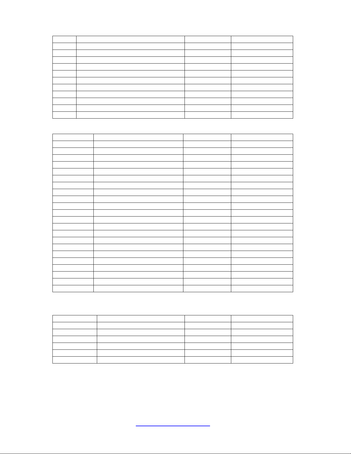
Ref # Function Manufacture Device #
Q1 SQ CONTROL KEC KTC3875Y
Q3, 4 NB KEC KTC3880
Q5 NB KEC KTK211
Q6 NB S/W KEC KTA1505Y
Q7 NB S/W KEC KTC3880
Q11 RF AMP KEC KTK211
Q19 RF GAIN AMP KEC KTC3880
Q22 1ST MIXER KEC KTC3875Y
IC-2 SQ, METER, AGC CONTROL INTEGRAL IL324
IC-1 FM DET UTC UTC3361
Q31 ANL KEC KRC112
AUDIO SECTION
Ref # Function Manufacture Device #
Q17, 63 AUDIO PRE AMP KEC KTC3875Y
IC-6 AUDIO POWER AMP SGSTOMSON TDA2003
IC-4AB MIC PRE AMP/FM LPF KEC KIC4558
Q44 MOD ALC S/W KEC KTC3875
Q43 MOD ALC S/W KEC KTA1504
Q64 AM ALC SENSE KEC KTC3875
Q56, 58 ALC CONTROL KEC KTC3876
Q57 ALC CONTROL KEC KTA1505
Q59 FM S/W KEC KRC110S
Q39 FM TX S/W KEC KRC112S
Q42 FM TX S/W KEC KRA102S
Q67 HI/LO S/W KEC KRC102S
Q65 RF POWER CONTROL TOSHIBA 2SA1943
Q66 RF POWER CONTROL KEC KTA1001
Q68 RF POWER CONTROL KEC KTC3875
Q32 ECHO S/W KEC KTC3875
Q77 ECHO S/W KEC KRC111
Q76 PA S/W KEC KRC111
Q13 PA AMP KEC
IC502 ECHO IC HOLTEK HT8970
IC-501 ECHO AMP KEC KIA4558
IC11 AM MOD AMP SGSTOMSON TDA2005
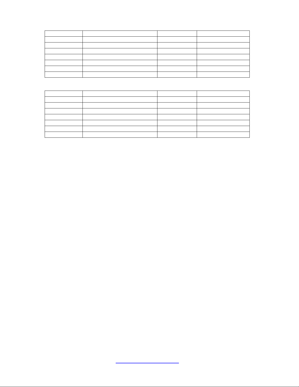
TX SECTION
Ref # Function Manufacture Device #
IC26 MIER KEC KIA6058F
Q12 BUFFER AMP KEC KTC3880
Q69 PRE DRIVER KEC KTC3880
Q71 PRE DRIVER SANYO 2SC2314
Q72 DRIVER MITSUBISHI RD06HHF1
Q73, Q74 POWER MITSUBISHI RD16HHF1
RECEIVER SECTION
http://www.cbtricks.com/
Preliminary Information (There will be updates)
Page 3
Cobra150GTL DX
PLL SECTION
Ref # Function Manufacture Device #
IC7 CONTROL & PLL SANYO LC7152
Q53 10.695MHz OSC KEC KTC3880
Q75 10.695MHz OSC BUFF KEC KTC3880
Q37 VCO OSC KEC KTC3880
Q36, 38 VCO AMP KEC KTC3880
IC8 CPU IC TOSHIBA TMP87CH21DF
IC6 E-PROM INTERGRAL IL24C02
POWER SUPPLY SECTION
Ref # Function Manufacture Device #
IC-10 8V REGULATOR KEC 78LO8
IC-5, IC25 5V REGULATOR KEC 78SO5
Q2 TX S/W KEC KTA200
Q57 TX S/W KEC KRC110S
Q14 RX S/W KEC KRA200
Q55 RX S/W KEC KRC102
Q9 PA S/W KEC KRC112
http://www.cbtricks.com/
Preliminary Information (There will be updates)
Page 4

Cobra150GTL DX
SET DC POWER SUPPLY VOLTAGE AT 13.8VOLT DC.
WATTMETER (50 OHM) TO THE ANTENNA CONNECTOR
PLL CIRCUIT ALIGNMENT PROCEDURE :
(1) SET TRANSCEIVER TO FREQUENCY 28.000MHz
(2) WHILE IN RECEIVER MODE, CONNECT OSCILLOSCOPE DC PROBE TO TP1 (SEE
PARTS LOCATION).
(3) ADJUST T712 AND OBSERVE THE DC LEVEL SWING BETWEEN 0.2 TO +7 VOLT DC.
THEN SET THE DC LEVEL TO 2.8 VOLT
(4) CHANGE TO BAND D, CHECK THE DC LEVEL SHOULD BE < 6V
(5)
WHILE IN RECEIVER MODE, CONNECT OSCILLOSCOPE DC PROBE TO TP2 (SEE
PARTS LOCATION).
(6) ADJUST T713 FOR MAXIMUM LEVEL
(7) SET RECEIVER TO FREQUENCY 28.000MHz. CONNECT OSCILLOSCOPE PROBE TO
TP4 OF CON2 AND MAXIMIZE RF LEVEL THROUGH T717.
(8) WHILE IN RECEIVER MODE, CONNECT FREQUENCY COUNTER PROBE TO TP3 (SEE
PARTS LOCATION).
(9) SET THE FREQUENCY 28.000MHz BY MOVING TUNE SWITCH THEN ADJUST
TRIMMER CT1 TO FREQUENCY 17.305MHz
CARRIER OSCILLATOR PORTION PROCEDURE :
(1) SET TRANSCEIVER TO FREQUENCY 28.000MHz
(2)
PRESS TO PTT
(3)
WHILE IN TRANSMIT AM/FM MODE.
(4) ADJUST CT2 TO OBTAIN 28.000MHz READING.
http://www.cbtricks.com/
Preliminary Information (There will be updates)
Page 5

Cobra150GTL DX
RF AMP CIRCUITS ALIGNMENT PROCEDURE :
1.RX ALIGNMENT
-AM
(1)
CONNECT THE PROVE OF RF SIGNAL MEASURING EQUIPMENT BETWEEN GROUND
AND ANNTENA POINT. SET THE SINAD OF SSG TO -47dBm AND THEN ADJUST
T703,704,705,706,707,708,710 FOR MAXIMUM READING ON THE EQUIPMENT.
(2)
AT -47 dBm SIGNAL, SQUELCH KNOB AT MAX. ALIGN THE SQUELCH CLOSE TO
OPEN AT RV2 WITH HYSTERISIS OF 2 - 5 dB.
(3)
AT 100 uV SQUELCH AT MINIMUM AND MODUALTION AT OFF CONDITION ALIGN
RV15 FOR S-9 SPECS 50 - 200 uV.
(4)
INSERT THE NB TESTER TO ANTENNA, MIN.SQUELCH, MAX. VOLUME, CONNECT
OSCILLOSCOPE TEST PROBE TO COLLECTOR OF Q6 AND ADJUST T701 TO
MAXIMUM READING OF EQUIPMENT.
-FM
(1)
CHANGE TO FM BAND .
SET THE SINAD OF SSG TO -47dBm AND THEN ADJUST T702 MAXIMUM READING
ON THE EQUIPMENT.
2.TX ALIGNMENT
(1) SET TRANSCEIVER TO FREQUENCY 29.7000MHz BAND D.
(2)
TEST EQUIPMENT CONNECTION. AT THE BOTTOM CONNECT RF POWER METER,
RF VTVM AND OSCILLOSCOPE TO ANTENNA JACK.
(3) ADJUST T718,719,720,721,722.723 COILS TO OBTAIN THE MAXIMUM INDICATION ON
RF VTVM
(4) ADJUST L21 TO SET POWER LEVEL FROM 15 WATTS NO MODULATION.
(5) WHILE IN AM TX MODE HI/LOW SWITCH TO LOW, NO MODULATION ADJUST RV9 TO
OBTAIN RF CARRIER POWER OF 4W ON RF POWER METER.
(6) SWITCH TO LOW POWER AND ADJUST RV4 TO OBTAIN 95% MODULATION TO ALL
BANDS.
(7) WHILE IN AM. TX. MODE. AF SIGNAL 30mV ADJUST RV12 TO OBTAIN 95%
MODULATION.
(8)
ON ALL BANDS WHILE IN AM TX MODE NO MODULATION AND HI/LOW SWITCH TO
HIGH ADJUST RV1 SO THAT THE METER INDICATE RF = 9 (S9)
(9) WHILE IN FM. TX. MODE. AF SIGNAL 30mV ADJUST RV5 TO OBTAIN 2.5KHz
DEVIATION.
(10)
(11)
INSERT 100 OHM DUMMY LOAD TO ANTENNA AND SWITCH TO FM LOW POWER, NO
MODULATION, CALIBRATION MODE WHILE IN TX MODE, ADJUST CALIBRATION
KNOB TO ATTAIN CAL LEVEL ON METER.
SWITCH TO SWR MODE AND ADJUST RV17 TO SET SWR =2.
http://www.cbtricks.com/
Preliminary Information (There will be updates)
Page 6

Cobra150GTL DX
http://www.cbtricks.com/
Preliminary Information (There will be updates)
Page 7

Cobra150GTL DX
A description of all circuits and devices provided for determining and stabilizing frequency:
Frequency (from 28.000mhz to 29.695mhz) of transmitting, as receiving, frequencies are provided by
PLL (phase locked loop) circuitry. The purpose of the PLL is to provide a multiple number of frequencies
from VCO (voltage controlled oscillator) with quartz crystal accuracy and stability from one crystal
oscillator reference frequency.
Therefore the VCO frequency is as accurate and stable as the crystal oscillator itself. The reference
crystal oscillator frequency is 10.240Mhz. And the VCO frequency 17.305mhz or local oscillators
10.695Mhz is mixer to obtain 28mhz band transmit frequency. And accurate as the 10.240mhz crystal
oscillators. Therefore the TX frequencies are as stable and accurate as the 10.240mhz crystal oscillators.
Stable and accurate within 18ppm over the temperature range between-30°C and 50°C, the transmitted
frequencies are also stable within 25ppm over the same temperature range.
DESCRIPTION OF FREQUENCY DETERMINING CIRCUIT:
To eliminate frequency drift to power supply variation. A regulated supply is provided for PLL operation.
The regulator consists of a regulated IC10 (8v) the 10.240Mhz crystal oscillator active part is included in
the PLL IC7.
See equivalent circuit block diagram of the PLL IC7.
VCO AND FREQUENCY MIXER.
The VCO circuit consists of following, Variator (DC voltage dependent variable capacitor) diode D30, D31
tuning coil T712. The oscillator of VCO frequency is done by a Q37 and T713.
The resulting 28Mhz output frequency is filtered by T720, T721, T722, T723, Q69 is a pre-amplifier, but is
also as go-no go type switch when illegal transmit frequency is generated. The logic circuit determining
the illegal frequencies is located inside the PLL IC7.
Q71, Q72 is a driver circuit for TX output. And Q73, Q74 is the final power amplifier the class AB type
amplifier output, signal is filtered by low pass filter consisting of L230, L231, L22, L24, C305, C306,
C311, C620, C621 make up a series resonant and the remaining l/C represents low pass filter.
DESCRIPTION OF ANY CIRCUITS OR DEVICES EMPLOYED FOR SUPPRESSION OF :
SPURIOUS RADIATION
When two frequencies are mixed in non-linear devices to obtain a desired output frequency, almost
unlimited number of spurious frequencies are generated at the same time. The undesired spurious
frequencies are restudied from the differences and the summations of the two frequencies and their
harmonics. The far-out frequencies can easily be filtered out. But the most difficult frequencies are those
close to the desired output center frequency.
A frequency mixer circuit used in this unit because it is far better than a mixer circuit in eliminating
spurious. Also important factors contributing to spurious are poor ground path.
Following steps are taken to eliminate spurious level TP will below 60db :
(1) Frequency mixer circuit is employed.
(2) Ground path of the printed circuit board is carefully laid out.
(3) Adequate band pass filter circuits are employed to eliminate spurious at the frequency mixer output.
http://www.cbtricks.com/
Preliminary Information (There will be updates)
Page 8

Cobra150GTL DX
LIMITING MODULATION
Since the nominal microphone (dynamic MIC) output level is about 0.6mv. The overall gain of the audio
amplifier is set so that 3mv (at 1khz) will modulate RF signal to 50% then a very effective ALC (automatic
level control) circuit.
It is used to limit audio gain so as not to over modulate beyond 95% the dynamic range of the ALC circuit
for this purpose is effective over 50 db input increase. The output audio level is sensed by Q64 and set
by resistor RV12. A positive going signal will trigger open the Q43, Q44.
LOW POWER
When all the coils are adjusted for peak, the RF power output shall not exceed 4.4 watts at low power
mode.
SUPPRESSION OF HARMONICS RADIATION
The class AB type amplifier output signal is filtered by low pass filter consisting of L230, L231, L22, L24,
C305, C306, C311, C620, C621 make up a series resonant circuit and the remaining l/C represents low
pass filter.
The harmonics radiation are suppressed by these filter circuits sufficiently and reduced to below 60db.
http://www.cbtricks.com/
Preliminary Information (There will be updates)
 Loading...