


150GTL ALIGNMENT REVISION: 1.0 BURKE
ALIGNMENT PROCEDURE
'RZQORDGHGIURPZZZFEUDGLRQO
MODEL: 150GTL
REVISION: 1.1
DATE: 02/14/06
PREPARED BY: BURKE
Total Pages: 6 pages
Page:1 print date: 2/14/06

150GTL ALIGNMENT REVISION: 1.0 BURKE
150GTL ALIGNMENT INSTRUCTION
1 TEST CONDITION:
1.0. TEST TEMPERTAURE: 77 ±9 °F
1.1. STANDARD DC POWER: 13.8VDC
1.2. STANDARD AUDIO LOADING: 8 Ω
1.3. ANTENNA IMPEDANCE: 50 Ω
1.4. STANDARD REF. MODULATION: AM 30%
FM 2.5KHz
1.5. PULSE GENERATOR: 1µS pulse @ 100mS and 1V peak-to-peak amplitude,
with rise and fall time of less than 10nS.
1.6. TEST EQUIPMENT SETUP AS BELOW:
A. TX test equipment setup:
Power
Supply
Modulation
Meter
RF
Wattmeter
Dummy
Load
150 GTL
Generator
Audio
Page:2 print date: 2/14/06

150GTL ALIGNMENT REVISION: 1.0 BURKE
RF Signal
B. RX test equipment setup:
AC
VTVM
Generator
Oscilloscope
150GTL
Power
Supply
8 ohm Load
Noise Pulse
Generator
2.0
MAIN ALIGNMENT
2.1 PLL Alignment
STEP PRESET TO CONNECTIONS ADJUST PROCEDURE
RX mode, AM,
1
28.000MHz
2 Change to Band D Oscilloscope to TP1
Oscilloscope to TP1 T712
DC level should be < 6V
Check for range of 0.2 to
7VDC, then set to 2.8V
3 Same as step 1 Oscilloscope to TP2 T713 Adjust for maximum output
4 Same as step 1
5 Same as step 1
2.2 Carrier Alignment
STEP PRESET TO CONNECTIONS ADJUST PROCEDURE
TX mode, AM,
1
28.000MHz
Page:3 print date: 2/14/06
Oscilloscope to 4th test
point of CON2
Frequency counter to
TP3
Frequency counter to
TP3
T717 Adjust for maximum output
CT1
CT2 Adjust for 28.000MHz
Adjust for 17.305MHz
(frequency – 10.695)

150GTL ALIGNMENT REVISION: 1.0 BURKE
T703, T704,
T705, T706,
T707, T708,
modulation, RF output 1500µV
3.0 RECEIVER ALIGNMENT
Connect an AC VTVM with 8 ohm load across speaker coil.
Adjust volume control to obtain a suitable indication.
Set generator output low enough to prevent AGC limiting.
Preset controls as follows, unless otherwise noted:
RF Gain maximum, Squelch minimum, NB/ANL off.
STEP PRESET TO CONNECTIONS ADJUST PROCEDURE
Output of signal generator to
RX mode, AM
1
28.000MHz
Same as step 1,
2
squelch to
maximum
antenna connector.
Freq. = 28.000MHz, 1KHz 30%
modulation, RF output 1µV
Output of signal generator to
antenna connector.
Freq. = 28.000MHz, 1KHz 30%
T710
RV2
Adjust for maximum signal on
VTVM
SQUELCH RANGE
Adjust just until squelch opens
3 Same as step 1
Output of signal generator to
antenna connector.
Freq. = 28.000MHz, NO
modulation, RF output 100µV
RV15
SIGNAL METER
Adjust for a reading of S-9 on the
analog meter of the radio
Output of signal generator and
RX mode, AM,
28.000MHz,
4
NB/ANL switch
set to NB/ANL
noise pulse generator to antenna
connector.
Freq. = 28.000MHz, 1KHz 30%
modulation, RF output 1µV.
T701
NOISE BLANKER
Adjust for maximum amplitude
on oscilloscope
Oscilloscope to collector of Q6
Output of signal generator to
RX mode, FM,
5
28.000MHz
antenna connector.
Freq. = 28.000MHz, 2.5KHz
T702
Adjust for maximum signal on
VTVM
deviation, RF output 1µV
4.0 TRANSMITTER ALIGNMENT
Maintain a 50 ohm 25 watt dummy load on the antenna connector for the following steps.
Preset controls as follows, unless otherwise noted:
RF Power set to HI, Mic Gain to minimum.
STEP PRESET TO CONNECTIONS ADJUST PROCEDURE
T718, T719,
T720, T721,
T722, T723
Adjust for maximum RF output
RF POWER - HI
Adjust for 13-17 watts on all
bands
RF POWER - LO
Adjust for 4 watts
1
TX mode, AM,
29.700MHz
RF wattmeter to antenna
connector
2 Same as step 1 Same as step 1 L21
3
Same as step 1,
Power switch to LO
Same as step 1 RV9
Page:4 print date: 2/14/06

150GTL ALIGNMENT REVISION: 1.0 BURKE
STEP PRESET TO CONNECTIONS ADJUST PROCEDURE
RF POWER METER
Adjust for a reading of S-9 on the
analog meter of the radio
AMC CONTROL - HI
Adjust for 90% modulation on
all bands
AMC CONTROL - LO
Adjust for 90% modulation on
all bands
4
5
6
TX mode, AM,
29.700MHz
TX mode, AM,
29.700MHz
Mic Gain to
maximum
Same as step 5,
Power switch to LO
RV1
Modulation meter to
antenna connector.
Insert a 1KHz, 30mV
RV12
signal to microphone
input.
Same as step 5 RV4
TX mode, FM,
7
29.700MHz
Mic Gain to
Same as step 5 RV5
DEVIATION LIMITER
Adjust for 2.5KHz deviation
maximum
SWR METER
8
TX mode, AM,
Power switch to LO,
Mic Gain to
minimum, S/RF
switch set to CAL
Connect a 100 ohm
non-inductive dummy
load to the antenna
connector
RV17
Adjust SWR Cal knob so analog
meter on radio goes to CAL
mark. Then set S/RF switch to
SWR and adjust RV17 for an
SWR reading of 2 on the analog
meter of the radio.
9
TX mode, AM,
Power switch to LO,
Mic Gain to
minimum
Short the antenna output
to ground
RV3 (located
on back of
front panel)
ANTENNA LIGHT
Adjust RV3 just until the
antenna light comes on
Page:5 print date: 2/14/06

150GTL ALIGNMENT REVISION: 1.0 BURKE
Page:6 print date: 2/14/06

150GTL ALIGNMENT REVISION: 1.0 BURKE
REVISION HISTORY
1.0 – Initial release
1.1 – Added section Step 9 in Section 4
Page:7 print date: 2/14/06


150GTL Channel Display
The 150GTL has 4 bands which cover frequencies from 28.000 to 29.700 MHz in 5KHz steps.
The dual seven-segment channel display indicates the operating frequency.
BAND FREQUENCY RANGE CHANNEL DISPLAY RANGE
A 28.000 to 28.495 00 to 49.
B 28.500 to 28.995 50 to 99.
C 29.000 to 29.495 0.0 to 4.9.
D 29.500 to 29.700 5.0 to 7.0
You must be careful to note the decimal points!
This decimal point
shows the MHz band.
OFF = 28.xxx MHz
ON = 29.xxx MHz
These two digits are
determined by the status
of the decimal between
the channel numbers.
Decimal OFF = 28
Decimal ON = 29
This decimal point
shows the last digit.
OFF = xx.xx0 MHz
ON = xx.xx5 MHz
x x . x x x MHz
These two digits are
taken directly from the
channel display.
The last digit is determined
by the status of the far-right
decimal point.
Decimal OFF = 0
Decimal ON = 5

NOTE: PIN 61 - 80 NO CONNECTION
SUPPLY VOLTAGE: 13.8 V
BAND A ( 28.000 MHz)
RX TESTING
PIN
NO.
1 V 0 0 0
GROUND
2 V 2.31 2.31 2.31
RX/TX
3 V 2 2 2
RX/TX
4 V 4.9 4.9 4.9
RX/TX
5 N.C. N.C. N.C.
NO CONNECTION
6 N.C. N.C. N.C.
NO CONNECTION
7 V 0 0 0
GROUND
8 N.C. N.C. N.C.
NO CONNECTION
9 V 0 0 0
DURING STANDBY
WHEN CH. SW. TURN ON TO DOWN POSITION
10 V 4.9 4.9 4.9
RX/TX
11 V 0.44 0.44 0.44
RX/TX
12 V 0 0 0
DURING STANDBY
13 V 4.9 4.9 4.9
RX/TX
14 V 4.86 4.86 4.86
RX/TX
15 mV 3.5 3.5 3.5
RX/TX
16 mV 3.7 3.7 3.7
RX/TX
NO CONNECTION
17 N.C. N.C. N.C.
DURING STANDBY
18 V 0 0 0
WHEN CH. SW. TURN ON TO UP POSITION
STANDBY
19 V 0 0 0
RX/TX
20 mV 7.4 7.4 7.4
RX
21 mV 4.2 4.2 4.2
TX
RX MODE /10 KHZ SW. ON
22 V 4.8 4.8 4.8
TX MODE /10 KHZ SW. ON
RX OPERATION
23 V 4.9 4.9 4.9
TX OPERATION
RX OPERATION
24 mV 4.6 4.6 4.6
TX OPERATION
RX
25 V 5 5 5
TX
RX
26 mV 28 28 28
TX
27 N.C. N.C. N.C.
NO CONNECTION
28 V 0 0 0
RX/TX OPERATION
RX/TX OPERATION
29 V 4.96 4.96 4.96
BAND SWITCH SET TO A BAND / WHEN SET TO
30
OTHER BAND PIN IS EQUAL TO ZERO VOLT
BAND SWITCH SET TO B BAND / WHEN SET TO
31
OTHER BAND PIN IS EQUAL TO ZERO VOLT
32
BAND SWITCH SET TO C BAND / WHEN SET TO
OTHER BAND PIN IS EQUAL TO ZERO VOLT
BAND SWITCH SET TO D BAND / WHEN SET TO
33
OTHER BAND PIN IS EQUAL TO ZERO VOLT
MODE SW. SET TO P.A. FUNCTION
34 mV
RX/TX OPERATION
35
RX/TX OPERATION
36
NO CONNECTION
37 N.C. N.C. N.C.
RX OPERATION
38 mV 173 173 173
TX OPERATION
RX/TX OPERATION
39 V 4.2 4.2 4.2
RX/TX OPERATION
40 V 4.83 4.83 4.83
RX/TX OPERATION
41 V 0 0 0
RX/TX OPERATION
42 V 0 0 0
PIN 43-56 NO CONNECTION
43 N.C. N.C. N.C.
RX
57 mV 40 40 40
TX
RX
58 mV 40 40 40
TX
59 mV 41 41 41
RX/TX OPERATION
60 V 0 0 0
SWITCH CONDITION
UNIT PA AM FM
V 4.7 4.7 4.7
V 4.7 4.7 4.7
mV 5.1 5.1 5.1
V 3 3 3
V 0.45 0.45 0.45
V 4.6mV 4.8 4.8
mV 5V 40.2 40.2
mV 28 29.2 29.2
4.75V
4.75 4.75V
V
V
V 5 5 5
V 4.6 4.6 4.6
mV 173 172 172
mV 41 41 41
4.75 4.75 4.75
4.75 4.75
4.7V 2 2
4.75 4.75
4.75
4.75


PIN
NO.
PIN
NO.
IC 502 (HT8970)
TEST CONDITION:
SUPPLY VOLTAGE: 13.8 V
BAND A ( 28.000 MHz)
SWITCH CONDITION
1 V 6.13 5.86 5.86
2 V 3.5 2.9 2.9
3 V 0 0 0
4 V 0 0 0
5 V 3.4 3.25 3.24
6 V 3.06 2.9 2.9
TX OPERATION W/ MODULATION
7 V 0.78 3 3
TX OPERATION W/ MODULATION
8 V 0.79 3 3
9 V 3.1 2.9 2.9
10 V 3.06 2.9 2.9
11 V 3.06 2.9 2.9
12 V 3.09 2.9 2.9
13 V 3.05 2.9 2.9
14 V 3.06 2.9 2.9
15 V 3.08 2.9 2.9
16 V 3.06 2.9 2.9
TX OPERATION
TX OPERATION
GROUND
GROUND
TX OPERATION
TX OPERATION
TX OPERATION
TX OPERATION
TX OPERATION
TX OPERATION
TX OPERATION
TX OPERATION
TX OPERATION
TX OPERATION
UNIT PA AM FM
IC 9 (TDA 2003V)
SWITCH CONDITION
1
2
3 V 0 0 0
4 V 6.42 6.42 6.42
5 V 13.7 13.7 13.7
VOL. MIN
VOL.MAX.
VOL. MIN
VOL.MAX.
GROUND
VOL. MIN
VOL.MAX.
SUPPLY VOLTAGE
UNIT PA AM FM
V 1.38 1.38 1.38
V 1.28 1.28 1.28
V 0.82 0.82 0.82
V 0.64 0.69 0.69
V 6.18 6.18 6.18

PIN
NO.
PIN
NO.
IC 26 (KIA 6058 F)
SWITCH CONDITION
1 V 0 1.08 1.08
2 V 0.03 1.77 1.77
3 V 0 6.9 6.9
4 V 0.04 1.74 1.74
5 V 0 0 0
6 V 0 6.8 6.8
7 V 0 6.86 6.85
8 V 0 6.9 6.9
TX
TX
TX
TX
GROUND
TX
TX
TX
UNIT PA AM FM
IC 11 (TDA- 2005)
SWITCH CONDITION
1 V 1.3 1.3 1.3
2 V
3
4 V 0.73 0.71 0.72
5 V 1.32 1.23 1.3
6 V 0 0 0
7
8
9
10
TX MODE W/ MODULATION
TX MODE W/O MODULATION
TX MODE W/ MODULATION
TX MODE W/O MODULATION
TX MODE W/ MODULATION
TX MODE W/O MODULATION
TX MODE W/ MODULATION
TX MODE W/O MODULATION
TX MODE W/ MODULATION
RX/TX
RX/TX
RX
RX/TX
TX
GROUND
RX
RX
RX
RX
UNIT PA AM FM
0.76 0.76 0.76
V
V 8.47 7.8 8.3
V 13.2 13.2 13.2
V 13.27 12.9 13
V 13.27 11.8 12.9
V 7 7 7
V 7 6.85 6.85
V 7 6.5 6.85
V 13.7 13.7 13.7
V 13.7 13.4 13.4
V 13.7 12.5 13.4
V 7 7 7
V 7 6.8 6.8
V 7 6.5 6.8
8.47 8.47 8.47
PIN
NO.
PIN
NO.
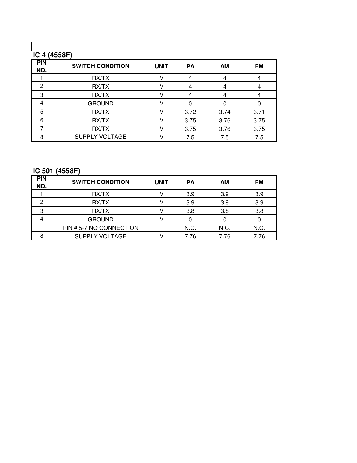
IC 4 (4558F)
SWITCH CONDITION
1 V 4 4 4
2
3 V 4 4 4
4
5
6
7
8
RX/TX
RX/TX
RX/TX
GROUND
RX/TX
RX/TX
RX/TX
SUPPLY VOLTAGE
UNIT PA AM FM
V 4 4 4
V 0 0 0
V 3.72 3.74 3.71
V 3.75 3.76 3.75
V 3.75 3.76 3.75
V 7.5 7.5 7.5
IC 501 (4558F)
SWITCH CONDITION
1 V 3.9 3.9 3.9
2
3 V 3.8 3.8 3.8
4
PIN # 5-7 NO CONNECTION
8
RX/TX
RX/TX
RX/TX
GROUND
SUPPLY VOLTAGE
UNIT PA AM FM
V 3.9 3.9 3.9
V 0 0 0
N.C. N.C. N.C.
V 7.76 7.76 7.76

PIN
NO.
IC 7 (LC7152)
SWITCH CONDITION
1 V 2.1 2.1 2.1
2
3
4
5
6
7 N.C. N.C. N.C.
8 V 0 0 0
MODE SW. SET TO BAND A
9
10
11
12
13 NO CONNECTION N.C. N.C. N.C.
14 V 2.4 2.4 2.4
15 V 0 0 0
16 N.C. N.C. N.C.
17 V 4.8 4.8 4.8
24 V 2.2 2.2 2.2
MODE SW. SET TO BAND B
MODE SW. SET TO BAND C
MODE SW. SET TO BAND D
MODE SW. SET TO BAND A
MODE SW. SET TO BAND B
MODE SW. SET TO BAND C
MODE SW. SET TO BAND D
MODE SW. SET TO BAND A
MODE SW. SET TO BAND B
MODE SW. SET TO BAND C
MODE SW. SET TO BAND D
MODE SW. SET TO BAND A
MODE SW. SET TO BAND B
MODE SW. SET TO BAND C
MODE SW. SET TO BAND D
PIN 18-23 NO CONNECTION
RX/TX
RX
TX
RX
TX
RX
TX
NO CONNECTION
NO CONNECTION
NO CONNECTION
GROUND
RX/TX
GROUND
NO CONNECTION
RX/TX
RX/TX
UNIT PA AM FM
mV 3.9 3.9 3.9
mV 3.9 4.5 4.5
mV 3.5 3.5 3.5
mV 3.5 4.1 4.1
mV 35.8 35.8 35.8
mV 35.8 36.5 36.4
N.C. N.C. N.C.
N.C. N.C. N.C.
V 1 1 1
V 0.95 0.95 0.95
V 0.9 0.9 0.9
V 0.85 0.85 0.85
V 1 1 1
V 0.95 0.95 0.95
V 0.9 0.9 0.9
V 0.85 0.85 0.85
V 1 1 1
V 0.95 0.95 0.95
V 0.9 0.9 0.9
V 0.85 0.85 0.85
V 2.8 2.8 2.8
V 4 4 4
V 4.9 4.9 4.9
V 5.6 5.6 5.6
N.C. N.C. N.C.

PIN
NO.
IC 6 (24C02)
SWITCH CONDITION
1 V 0 0 0
5 mV 36 36 36
6 V 4.9 4.9 4.9
7 V 0 0 0
8 V 5 5 5RX/TX
PIN # 1-4 GROUND
RX/TX
RX/TX
GROUND
UNIT PA AM FM

PIN
NO.
IC 2 (IL324)
SWITCH CONDITION
RX MODE LEVEL AT 100µV
1
2
3
4
5
8
9
10
11 V 0 0 0
12
13
14
RX MODE LEVEL AT 200µV
RX MODE LEVEL AT 50µV
RX MODE LEVEL AT 100µV
RX MODE LEVEL AT 200µV
RX MODE LEVEL AT 50µV
RX MODE LEVEL AT 100µV
RX MODE LEVEL AT 200µV
RX MODE LEVEL AT 50µV
LEVEL AT -107dBm
LEVEL AT -87dBm
LEVEL AT -47dBm
LEVEL AT -27dBm
LEVEL AT 0dBm
PIN # 5-7 NO CONNECTION
SQ. MIN AT -47dBm
SQ. MAX. AT -47dBm
SQ. MAX. AT -52dBm
SQ. MIN AT -47dBm
SQ. MAX. AT -47dBm
SQ. MAX. AT -52dBm
SQ. MIN AT -47dBm
SQ. MAX. AT -47dBm
SQ. MAX. AT -52dBm
GROUND
LEVEL AT -107dBm
LEVEL AT -87dBm
LEVEL AT -47dBm
LEVEL AT -27dBm
LEVEL AT 0dBm
LEVEL AT -107dBm
LEVEL AT -87dBm
LEVEL AT -47dBm
LEVEL AT -27dBm
LEVEL AT 0dBm
LEVEL AT -107dBm
LEVEL AT -87dBm
LEVEL AT -47dBm
LEVEL AT -27dBm
LEVEL AT 0dBm
UNIT PA AM FM
V 0.04 2.38 2.38
V 0.04 2.52 2.52
V 0.04 2.24 2.24
V 0.04 1.18 1.18
V 0.04 1.25 1.25
V 0.04 0.94 0.94
V 0.04 1.18 1.18
V 0.04 1.25 1.25
V 0.04 1.1 1.1
V 0 7.86 7.86
V 0 7.82 7.82
V 0 7.77 7.77
V 0 7.76 7.76
V 0 7.72 7.72
N.C. N.C. N.C.
V 0.19 0 0
V 0.35 0 0
V 0.35 6.06 6.06
V 0.81 4.51 4.51
V 0.81 4.51 4.51
V 0.81 4.39 4.39
V 0.61 0.61 0.61
V 4.38 4.38 4.38
V 4.38 4.45 4.45
V 0.1 0.38 0.38
V 0.1 1.53 1.53
V 0.1 2.28 2.28
V 0.1 2.44 2.44
V 0.1 4.64 4.64
V 0.16 0.38 0.38
V 0.16 1.48 1.48
V 0.16 2.23 2.23
V 0.16 2.38 2.38
V 0.16 2.84 2.84
V 0.37 0.85 0.85
V 0.37 3.38 3.38
V 0.37 4.7 4.7
V 0.37 5.4 5.4
V 0.37 6.3 6.3

PIN
NO.
IC 1 (UTC3361)
SWITCH CONDITION
1 V 0 4.85 4.85
2 V
3 V -.16 4.5 4.5
4 V -.16 4.9 4.9
5 V 0.04 3.66 3.66
6
7
8 V -.17 4.9 4.9
9 V 0.02 2.15 2.15
10 N.C. N.C. N.C.
15 V 0 0 0
16 V -.03 1.72 1.71
RX OPERATION AT -47dBm
RX OPERATION AT -47dBm
RX OPERATION AT -47dBm
RX OPERATION AT -47dBm
RX OPERATION AT -47dBm
RX OPERATION AT -47dBm
RX OPERATION AT -47dBm
RX OPERATION AT -47dBm
RX OPERATION AT -47dBm
PIN # 10- 14 NO CONNECTION
GROUND
RX OPERATION AT -47dBm
UNIT PA AM FM
-.16 4.78 4.78
V 0.04 3.66 3.66
V 0.02 3.66 3.66


150GTL: L13,14,15
150GTL: T713,717
150GTL: J4,5
150GTL: D2,20
150GTL: D79
150GTL: D6,22,25,27,28,39,73,77,74
150GTL: D21,37
150GTL: D18,23,33,62,75,78
150GTL: D11,34
150GTL: D12,13,14,17,30,31,68,69,71,72
150GTL & 200GTL Parts List
COBRA P/N MODEL DESCRIPTION CIRCIUT SYMBOL
010-001 150, 200 Bracket, mounting
010-002 150 Capacitor, trimmer, 20pF, 150gtl CT1,2
010-003 200 Choke, 4.7µH, 200gtl L9,11
010-004 150 Choke, 6.8µH, 150gtl L2
010-005 150, 200 Choke, power input TF1
010-006 150, 200 Coil, 1µ H
010-007 150, 200 Coil, adjustable L21
010-008 150, 200 Coil, IFT T702
010-009 150, 200 Coil, IFT T701,707,708
010-010 150, 200 Coil, IFT T719
010-011 150, 200 Coil, IFT T712
010-012 150, 200 Coil, IFT
010-013 150, 200 Coil, IFT T703,723
010-014 150, 200 Coil, IFT T704,705,706
010-015 150, 200 Coil, IFT T718,720
010-016 150, 200 Coil, IFT T721,722
010-017 150 Coil, IFT, 150gtl T710
010-018 200 Coil, IFT, 200gtl T710
010-019 200 Coil, IFT, 200gtl T711
010-020 200 Coil, IFT, 200gtl T715,716
010-021 200 Coil, IFT, 200gtl T714
010-022 150 Connector assembly, frequency counter, 150gtl
010-023 150, 200 Connector, antenna ANT1
010-024 150, 200 Connector, external speaker
010-025 150, 200 Connector, microphone
010-026 150 Cover assembly, bottom, 150gtl
010-027 200 Cover assembly, bottom, 200gtl
010-028 150 Cover assembly, top, 150gtl
010-029 200 Cover assembly, top, 200gtl
010-030 150 Crystal, 10.24MHz, 150gtl X1
010-031 200 Crystal, 10.24MHz, 200gtl X2
010-032 150 Crystal, 10.695MHz, 150gtl X4
010-033 200 Crystal, 10.6975MHz, 200gtl X4
010-034 150, 200 Crystal, 4.194304MHz X3
010-035 150, 200 Diode, 1N60P
010-036 150, 200 Diode, 6A6 (6A, 600V) D48
010-037 200 Diode, band switch, KDS114, 200gtl D49
010-038 150, 200 Diode, chip, 6.8V zener
010-039 150, 200 Diode, chip, KDS160
010-040 150, 200 Diode, chip, KDS181S
010-041 150, 200 Diode, chip, KDS184S
010-042 150, 200 Diode, chip, KDS226
010-043 150, 200 Diode, chip, varicap, KDV251S-C-RTK
010-044 150, 200 Diode, schottky, RB706F D7,24
010-045 200 Diode, varicap, KDV350E, 200gtl D74
010-046 150 Escutcheon assembly, 150gtl
010-047 200 Escutcheon assembly, 200gtl
200GTL: L2,13
200GTL: T713
200GTL: J2,3
200GTL: D2,78
200GTL: D83
200GTL: D1,6,8,19,20,22,26,27,28,30,41,45,50,51,54,60,63,79,
200GTL: D21,37,46
200GTL: D4,5,9,16,18,33,39,42,43,44,47,52,55,58,80,81
200GTL: D11,34,38
200GTL: D10,12,13,14,17,29,31,68,69,71,72

010-048 150, 200 Filter, ceramic, 455KHz CF3
307-331-9-001
150GTL: IC9,12
150GTL: VR103
150GTL: RV4
150GTL: RV12
010-049 150 Heat sink, 150gtl
010-050 200 Heat sink, 200gtl
200 IC, audio amp, KIA7217AP, 200gtl IC11
010-051 150 IC, audio amp, TDA2003V, 150gtl IC9
010-052 150 IC, audio amp, TDA2005, 150gtl IC11
010-053 150, 200 IC, bipolar, KIA4558F IC4,501
010-054 150, 200 IC, bipolar, KIA6058F IC26
010-055 150 IC, CPU, 150gtl IC8
010-056 200 IC, CPU, 200gtl IC8
010-057 200 IC, double balanced mod, NJM1496, 200gtl IC3
010-058 150, 200 IC, echo, HT8970 IC502
010-059 150, 200 IC, EEPROM, HT24LC02 IC6
010-060 150, 200 IC, FM IF, UTC3361B IC1
010-061 150, 200 IC, IN74HC164AD
200GTL: IC18,24
010-062 150, 200 IC, OP AMP, IL324D IC2
010-063 150, 200 IC, PLL, LC7152 IC7
010-064 150, 200 IC, regulator, KIA7808AP/API IC10
010-065 150, 200 IC, regulator, KIA78L05F IC5,25
010-066 200 IC, switch, IW4066BD, 200gtl IC503
010-067 150, 200 Knob, channel
010-068 200 Knob, pushbutton, DIM / SWR, 200gtl
010-069 200 Knob, pushbutton, NB / HI PWR / R BEEP, 200gtl
010-070 150, 200 Knob, volume (inner)
010-071 150, 200 Knob, volume (outer)
010-072 150, 200 Knobe, mode (PA-AM-FM)
010-073 150, 200 Lamp, meter LED2
010-074 150, 200 LED, ANT light LED3
010-075 150, 200 LED, channel display DIS1, DIS7
010-076 200 LED, frequency display, 200gtl DIS1,2,3,4,5,6
010-077 150, 200 LED, RX / TX LED1
010-078 150 MCF, 10.695MHz, 150gtl
010-079 200 MCF, 10.695MHz, 200gtl CF2
010-080 200 MCF, 10.695MHz, 200gtl CF4
010-081 150, 200 Meter, analog MET1
010-082 150 Pot, DIM / SWR CAL, 150gtl VR107
010-083 200 Pot, ECHO / SWR CAL, 200gtl VR4
010-084 150, 200 Pot, MIC GAIN / RF GAIN
200GTL: VR103,105
010-085 150 Pot, TB / ECHO, 150gtl VR3
010-086 150, 200 Pot, volume / squelch VR101
010-087 150 Power cord assembly with fuse holder, 150gtl
010-088 200 Power cord assembly with fuse holder, 200gtl
010-089 150 Power cord pigtail assembly, 150gtl CON8
010-090 200 Power cord pigtail assembly, 200gtl
010-091 150, 200 Power supply assembly, EL
010-092 200 Relay, 200gtl RL1
010-093 150 Resistor, 10ohm 1W 5%, 150gtl R279
010-094 200 Resistor, 120ohm 2W 5%, 200gtl R346,355,356
010-095 150, 200 Resistor, 3.9ohm 2W 5% R290
010-096 150, 200 Resistor, 4.7K 2W 5% R331
010-097 150, 200 Resistor, trimmer, 100K RV1,2,15
010-098 150, 200 Resistor, trimmer, 10K
200GTL: RV6,14
010-099 200 Resistor, trimmer, 1K, 200gtl RV8,20
010-100 150, 200 Resistor, trimmer, 2.2K
200GTL: RV5,12
010-101 200 Resistor, trimmer, 22K, 200gtl RV3,23

010-102 150, 200 Resistor, trimmer, 4.7K
150GTL: RV5,9
150GTL: RV3,17
Switch, push, NB, PWR, R BEEP, 10KHz, SWR-S/RF, 200g
172-062-9-001
150GTL: Q8
150GTL: Q55,57
150GTL: Q9,25,32,39,59,79,80
150GTL: Q6,31,43,81
150GTL: Q1,10,13,17,26,28,44,64,68
150GTL: Q3,4,7,12,18,19,22,36,37,38,46,53,69,75
150GTL: Q73,74
200GTL: RV7,9
010-103 200 Resistor, trimmer, 470ohm, 200gtl RV19
010-104 150, 200 Resistor, trimmer, 47K
200GTL: RV4,21
010-105 150, 200 Screw, case
010-106 150, 200 Speaker SP1
010-107 150 Strain relief, power cord, 150gtl
010-108 200 Strain relief, power cord, 200gtl
010-109 150, 200 Switch, band (A-B-C-D) SW4
010-110 150, 200 Switch, channel SW1
010-111 200 Switch, mode (CW-FM-AM-USB-LSB), 200gtl SW12
010-112 150 Switch, mode (PA-AM-FM), 150gtl SW11
010-113 200 Switch, push, DIM/SWR, 200gtl SW17
010-114 200
SW2,3,5,8,14
010-115 150 Switch, slide (RF Power, 10KHz), 150gtl SW3,14
010-116 150 Switch, slide (S/RF, NB/ANL), 150gtl SW7,9
010-117 150, 200 Thumbscrew, for mounting radio to bracket
010-118 150 Transformer, audio, 150gtl
200 Transistor, 2SC2078, 200gtl Q72
010-119 200 Transistor, 2SC2290A, 200gtl Q35,40
010-120 150, 200 Transistor, 2SC2314 Q71
010-121 150 Transistor, driver, RD06HHF1 (30MHz, 6W), 150gtl Q72
010-122 150, 200 Transistor, KRA101S
200GTL: Q46
010-123 150, 200 Transistor, KRA102S Q42
010-124 150 Transistor, KRC101S, 150gtl Q33,59,67
010-125 150, 200 Transistor, KRC102S
010-126 150, 200 Transistor, KRC111S
200GTL: Q15,34,41,55,57
200GTL: Q9,13,16,20,29,32,39,45,47,48,50,77-81,84,85
010-127 150, 200 Transistor, KTA1001 Q66
010-128 150, 200 Transistor, KTA1504GR
200GTL: Q6,31,43,83
010-129 150, 200 Transistor, KTB1370 Q65
010-130 150, 200 Transistor, KTC3875Y
010-131 150, 200 Transistor, KTC3880S-Y
200GTL: Q1,8,17,44,49,63,64,68,75
200GTL:
010-132 150, 200 Transistor, PNP, KTA200 Q2,14
010-133 150, 200 Transistor, RD16HHF1 (30MHz, 16W)
200GTL: Q74
010-134 150, 200 Transistor., KTK211Y Q5,11
010-135 150, 200 Washer, rubber (for thumb screws)


LOCATION VALUE UNIT PA AM FM
Q18 C3880Y RX STANDBY CONDITION
Q11 KTK211Y
Q19 C3880Y RX
Q22 C3880Y RX
Q3 C3880Y
Q4 C3880Y
Q5 KTK2IIY RX
Q6 KTA1504 RX
Q36 C3880Y RX/TX MODE
Q37 C3880Y RX/TX MODE
Q38 C3880Y RX/TX MODE
SWITCH CONDITION
RX LEVEL AT -107dBm
RX LEVEL AT -47dBm
RX LEVEL AT 0dBm
NB SW. OFF
NB SW. ON
NB SW. OFF
NB SW. ON
B V 0 0 0
E V 0 0 0
C V 0 0 0
G V 0 0 0
D V 0 0.73 0.73
S V 0 7.2 7.2
G V 0 0 0
D V 0 0.78 0.78
S V 0 7.2 7.2
G V 0 0 0
D V 0.16 0.79 0.79
S V 0 7.2 7.2
B V -34.7mV 1.9 1.9
E V .3mV 1.2 1.2
C V -144mV 7.7 7.7
B V -15.5mV 0.77 0.77
E mV 0 163.6 163.7
C V -144.4mV 7.7 7.7
B mV 27.7 28.4 28.7
E V 0 0 0
C V 0.4 0.4 0.4
B V -146.5mV 0.722 0.72
E V 0 0 0
C V -146 4.5 4.5
B V 0.34 0.33 0.32
E V 0 0 0
C V 0.3 0.3 0.3
B V -.13 0.72 0.72
E V 0 0 0
C V 0.3 0.3 0.3
G V 0 0 0
D V -72mV 0.88 0.88
S V 0.74 6.9 6.9
B V -130mV 7.2 7.2
E V 145mV 7.8 7.8
C V 0 2.9 2.9
B V 0.714 0.714 0.714
E V 0 0 0
C V 4.15 4.15 4.15
B V 2.9 2.9 2.9
E V 2.2 2.2 2.2
C V 7.1 7.1 7.1
B V 3 3 3
E V 2.3 2.3 2.3
C V 7.67 7.67 7.67

LOCATION VALUE UNIT PA AM FM
Q26 C3875Y RX/TX MODE
Q28 C3875Y RX MODE
Q17 C3875Y RX MODE
Q1 C3875Y RX MODE
Q42 KRA102
Q39 C111 TX MODE
Q64 C3875Y
Q80 KRC111
Q25 C111
Q65 2SC1370
SWITCH CONDITION
RX MODE
TX MODE
RX MODE
TX MODE
RF PWR. SET TO HI PWR.
RF PWR. SET TO LO PWR.
RF PWR. SET TO HI PWR.
RF PWR. SET TO LO PWR.
RF PWR SW . SET TO HI PWR
RF PWR SW . SET TO LO PWR
STANDBY RF PWR SW . AT LO
PWR
STANDBY RF PWR SW . AT HI
PWR
B V .4mV 0.708 0.708
E mV 0 136 136
C V -034.8mV 1.6 1.6
B V -034mV 1.6 1.6
E V 0 1 1
C V 13.6 13.4 13.4
B V 0.64 0.64 0.64
E V 0 0 0
C V 4.2 4.2 4.2
B mV .77V 2 2
E V 0 0 0
C V 0.007 0.023 0.026
B mV 0 0.2 0.29
E V 0 0 0
C mV 160 158 7.5V
B V 0 7.5 5.2mV
E V 0 7.5 7.5
C mV 160 158 7.5V
B V 0.03 0.05 7.9
E V 0 0 0
C V 0 7.5 7.5
B V 0.84 0.84 0.84
E V 2.35 2.35 2.35
C V 7.9 7.9 7.9
B V 0.84 0.84 0.84
E V 2.35 2.01 2.05
C V 7.9 7.9 7.9
B V 0 0 0
E V 0 0 0
C V 0 4 0
B V 1.7 1.7 1.7
E V 0 0 0
C V 0 0 0
B V 0 0 0
E V 0 0 0
C V 0.84 0.84 0.84
B V 1.7 1.7 1.7
E V 0 0 0
C V 0 0 0
B V 13.5 13.5 13.5
E V 13.8 13.6 13.6
C V 13.8 13.7 13.7
B V 13.3 13 13
E V 13.8 13.7 13.7
C V 6.85 6.75 6.75
B V 13.3 13.3 13.3
E V 13.8 13.8 13.8
C V 6.85 6.85 6.85
B V 13.5 13.5 13.5
E V 13.8 13.8 13.8
C V 13.8 13.8 13.8

LOCATION VALUE UNIT PA AM FM
Q66 13.2
Q68 C3875Y
Q12 C3880Y TX MODE BOTH HI & LO PWR
Q69 C3880Y TX MODE BOTH HI & LO PWR
Q71 2SC2314 TX MODE BOTH HI & LO PW R
Q72
Q20 A200
RDO6HHF
1
SWITCH CONDITION
STANDBY RF PWR SW . AT LO
PWR
STANDBY RF PWR SW . AT HI
PWR
RF PWR SW . SET TO HI PWR
RF PWR SW . SET TO LO PWR
STANDBY RF PWR SW . AT LO
PWR
STANDBY RF PWR SW . AT HI
PWR
RF PWR SW . SET TO HI PWR
RF PWR SW . SET TO LO PWR
STANDBY RF PWR SW . AT LO
PWR
STANDBY RF PWR SW . AT HI
PWR
RF PWR SW . SET TO HI PWR
RF PWR SW . SET TO LO PWR
RX
TX
B V 13.2 13.2 13.2
E V 13.3 13.3 13.3
C V 6.85 6.85 6.85
B V 13.5 13.5 13.5
E V 13.5 13.5 13.5
C V 13.8 13.8 13.8
B V 13.5 13.2 13.2
E V 13.5 13.2 13.2
C V 13.8 13.4 13.4
B V 13.2 12.5 12.5
E V 13.3 13 13
C V 6.85 6.76 6.76
B V 7.4 7.4 7.4
E V 6.9 6.9 6.9
C V 13.2 13.2 13.2
B V 7.4 7.4 7.4
E V 13.8 13.8 13.8
C V 13.5 13.5 13.5
B V 7.4 7.4 7.4
E V 13.8 13.4 13.4
C V 13.5 13.4 13.16
B V 7.4 7.4 7.4
E V 6.9 6.8 6.8
C V 13.2 12.45 12.45
B V 0 1.32 1.32
E V 0 0.57 0.57
C V 0 5.64 5.64
B V 0 1.33 1.33
E V 0 0.58 0.58
C V 0 5.64 5.64
B V 0 1.28 1.28
E V 0 0.61 0.61
C V 0 7.52 7.52
B V 0 0 0
E V 0 0 0
C V 13.8 13.8 13.8
B V 0 0 0
E V 0 0 0
C V 6.85 6.85 6.85
B V 0 4.47 4.47
E V 0 0 0
C V 13.8 13.8 13.8
B V 0 4.47 4.47
E V 0 0 0
C V 6.85 6.75 6.75
B V 7.9 7.9 7.9
E V 7.9 7.9 7.9
C V 0 0 0
B V 0 7.12 7.12
E V 7.9 7.9 7.9
C V 0 7.6 7.6

LOCATION VALUE UNIT PA AM FM
Q9 C111
Q57 C102
Q75 C3880Y TX
Q53 C3880Y TX
Q46 C3880Y
Q59 KRC111 TX/RX
Q44 C3880Y
Q43 KTA1504
Q13 C3875Y TX/RX
Q79 KRC111 TALKBACK SW. ON
SWITCH CONDITION
RX
TX
RX
TX
RX
TX
TX MODE / MIC GAIN MINIMUM
TX MODE / MIC GAIN MAX.
STANDBY
RX
TX
B V 7.9 0 0
E V 0 0 0
C V 0 4.4 4.4
B V 7.9 0 0
E V 0 0 0
C V 0 0.61 0.61
B V 0 0 0
E V 0 0 0
C V 7.7 7.7 7.7
B V 0 4.8 4.8
E V 0 0 0
C V 7.7 0.02 0.02
B V 0 0.64 0.64
E V 0 0 0
C V 0 4.5 4.5
B V 0 1.9 1.9
E V 0 1.2 1.2
C V 0 7.1 7.1
B V 1.7 1.7 1.7
E V 1.3 1.3 1.3
C V 7.6 7.6 7.6
B V 1.7 1.8 1.8
E V 1.3 1.3 1.3
C V 7.6 7.6 7.6
B V 7.4 7.4 7.4
E V 0 0 0
C V 0 4 0
B V 0 0 0
E V 0 0 0
C V 0 0 0
B V 0 0.56 0
E V 0 0 0
C V 0 0 0
B V 0 0.72 0.72
E V 0 0 0
C V 0 4.5 4.5
B V 7.9 7.9 7.9
E V 7.9 7.9 7.9
C V 0 0.558 0.558
B V 7.9 7.5 7.9
E V 7.9 7.9 7.9
C V 0 0.65 0
B V 0.61 0 0
E V 0 0 0
C V 4.18 0 0
B V 7.95 7.95 7.95
E V 0 0 0
C V 0 0 0

LOCATION VALUE UNIT PA AM FM
Q14 A200
Q55 C102
Q73
Q74
Q81 A1504
Q81 A1015
RD16HHF
1
RD16HHF
1
SWITCH CONDITION
RX
TX
RX
TX
STANDBY MODE SW. AT HI PWR
STANDBY MODE SW. AT LO
PWR
TX MODE AT HI PW R
TX MODE AT LO PW R
STANDBY MODE SW. AT HI PWR
STANDBY MODE SW. AT LO
PWR
TX MODE AT HI PW R
TX MODE AT LO PW R
RX
TX
TX MODE W/ ANTENNA
TX MODE W/O ANTENNA
SW.SET TO SWR FUNC.
TX MODE W/O ANTENNA
SW.SET TO CAL FUNC.
B V 7.9 7.19 7.2
E V 7.95 7.95 7.95
C V -0.15 7.9 7.9
B V 7.9 7.9 7.9
E V 7.95 7.95 7.95
C V 0 -.14 -.14
B V 0 4.36 4.36
E V 0 0 0
C V 7.9 0.02 0.02
B V 0 0.59 0.59
E V 0 0 0
C V 7.9 7.9 7.9
B V 0 0 0
E V 0 0 0
C V 13.8 13.8 13.8
B V 0 0 0
E V 0 0 0
C V 6.85 6.85 6.85
B V 0 6.57 6.57
E V 0 0 0
C V 13.8 13.8 13.8
B V 0 0 0
E V 0 0 0
C V 6.85 6.85 6.85
B V 0 0 0
E V 0 0 0
C V 13.8 13.8 13.8
B V 0 0 0
E V 0 0 0
C V 6.85 6.85 6.85
B V 0 6.57 6.57
E V 0 0 0
C V 13.8 13.8 13.8
B V 0 0 0
E V 0 0 0
C V 6.85 6.85 6.85
B V 6.91 6.91 6.91
E V 5 5 5
C V 0 0 0
B V 6.91 6.82 6.82
E V 5 5 5
C V 0 0 0
B V 3.7 3.7 3.7
E V 3.7 3.7 3.7
C V 0 0 0
B V 3.7 0.03 0.03
E V 3.7 1.4 1.4
C V 0 0 0
B V 3.7 3.7 3.7
E V 3.7 3.7 3.7
C V 0 0 0
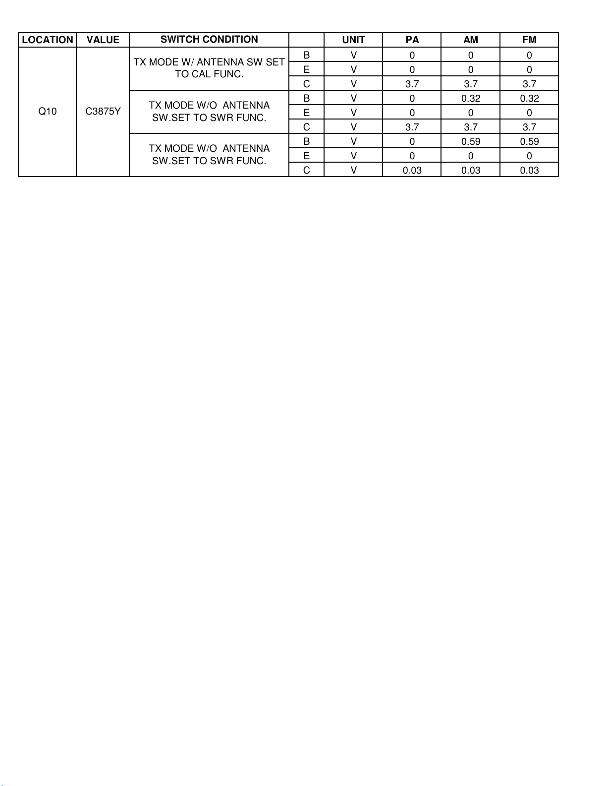
LOCATION VALUE UNIT PA AM FM
Q10 C3875Y
SWITCH CONDITION
TX MODE W/ ANTENNA SW SET
TO CAL FUNC.
TX MODE W/O ANTENNA
SW.SET TO SWR FUNC.
TX MODE W/O ANTENNA
SW.SET TO SWR FUNC.
B V 0 0 0
E V 0 0 0
C V 3.7 3.7 3.7
B V 0 0.32 0.32
E V 0 0 0
C V 3.7 3.7 3.7
B V 0 0.59 0.59
E V 0 0 0
C V 0.03 0.03 0.03

 Loading...