

Page 1
Robo-Arm™ LR Accessory
Kit 8560761701 For use with COATS Rim Clamp® Tire Changers
This is a supplement to your operating manual and covers the installation and use of the Robo-Arm LR accessory.
If you do not have your original operating manual, please call COATS at 1-800-688-6359 to request an additional
copy.
Installation Instructions
Operating Instructions
with Parts Identifi cation
READ these instructions before placing unit in
service. KEEP these and other materials delivered
with the unit in a binder near the machine for ease
of reference by supervisors and operators.
1601 J. P. Hennessy Drive, LaVergne, TN USA 37086-3565 615/641-7533 800/688/6359 www.ammcoats.com Manual Part No.: 8560762401 01
HENNESSY INDUSTRIES INC. Manufacturer of AMMCO
®
, COATS®. and BADA® Automotive Service Equipment and Tools. Revision: 02/12
Page 2
Installation Instructions
1. Before beginning any work, clear the area and posi-
tion the machine for easy access. Disconnect all power
sources, both air and electricity inputs. Allow any stored
air in the reservoir to escape by depressing the inflate
valve.
4. Next, remove nut on the bolt supporting the swing
arm pivot system. With the new 14-inch (356 mm) long
bolt push the old bolt out. Make sure the small washer
is on the head of the new bolt. Next, install the pivot pin
spacer, the swing arm (note position of the decal) with
pivot pin spacer, large washer and the lock nut.
Pivot Pin
Spacer
Figure 1 - Disconnect power and air sources.
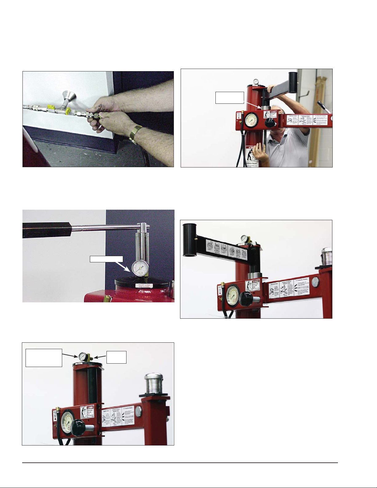
2. Verify the stored air pressure is zero by observing
the air pressure gauge on top of the tower (see photo).
Next with a 1 1/16-inch socket wrench, remove the
manifold with the gauge and safety valve.
Safety Valve
Figure 2 - Remove manifold with gauge and safety valve.
3. Next install the included manifold with the gauge
and safety valve plus a barbed hose fitting. Tighten until
the barbed fitting is located as shown in photo.
Figure 4 - Use new long bolt to push old bolt out.
5. Next, using large wrenches, tighten the assembly
to 240 ft. pounds torque (very tight). If the swing arm
rotation is too tight, loosen the lock nut until the swing
arm assembly rotates with a slight amount of resistance.
Figure 5 - Tighten swing arm to rotate with some resistance.
Manifold with
Gauge and
Safety Valve
Figure 3 - Install manifold, safety valve and barbed fitting.
Barbed
Fitting
2 • Tire Changers
Page 3
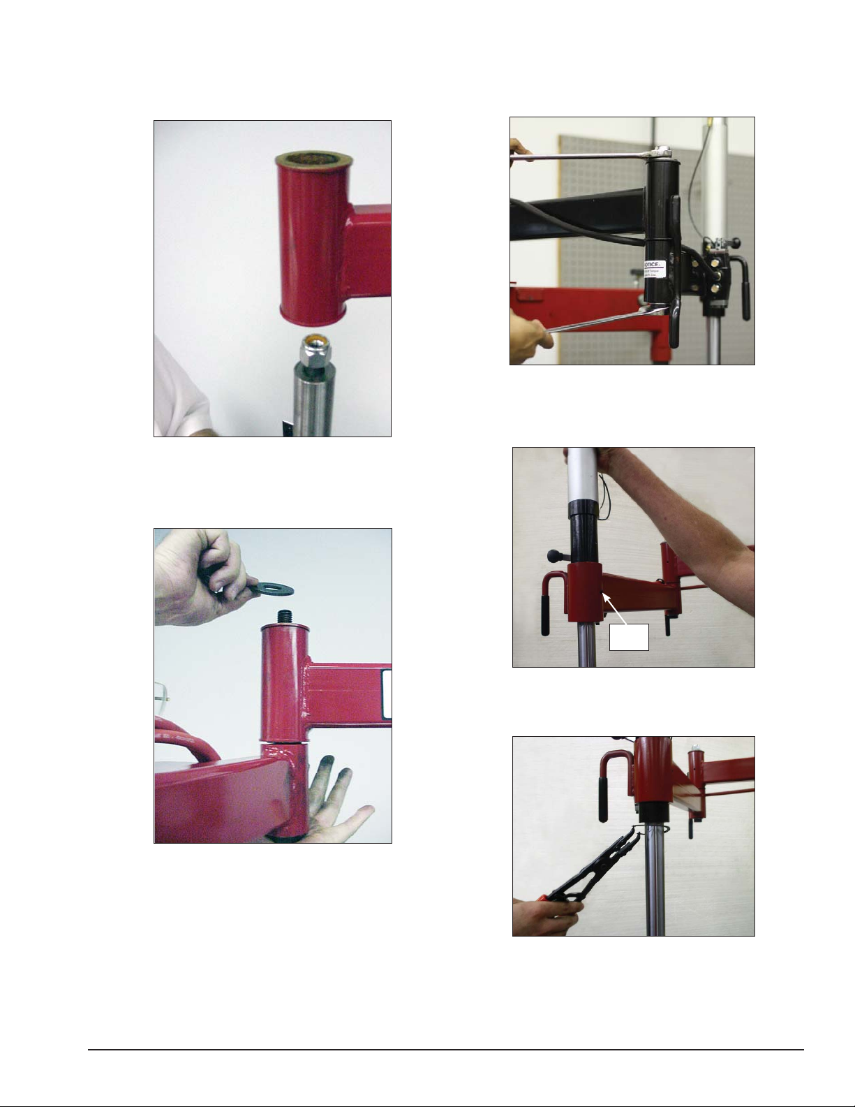
6. Locate arm with valve assembly, install the 10 1/2-
inch (267 mm) long bolt with head through the bottom
side, slide pivot pin over bolt and attach nut with only
one turn.
Figure 6 - Locate and position arm with cylinder.
8. Next, using large wrenches, tighten the assembly
to 240 ft. pound torque (very tight). Again, even though
the bolt is very tight, the assembly should be free to
rotate.
Figure 8 - Tighten the swing arm bolt.
9. Slide the cylinder through the cylinder arm bush-
ing, aligning the cylinder for set screw installation.
Tighten the set screw.
7. Slide the cylinder arm pivot pin through the swing
arm bushing, hold in position, remove nut and place
washer over bolt threads and assemble nut to bolt.
Figure 7 - Hold swing arm in position to install nut to bolt
Set
Screw
Figure 9 - Slide cylinder through cylinder arm bushing.
10. Install the external snap ring.
Figure 10 - Install external snap ring.
Tire Changers • 3
Page 4
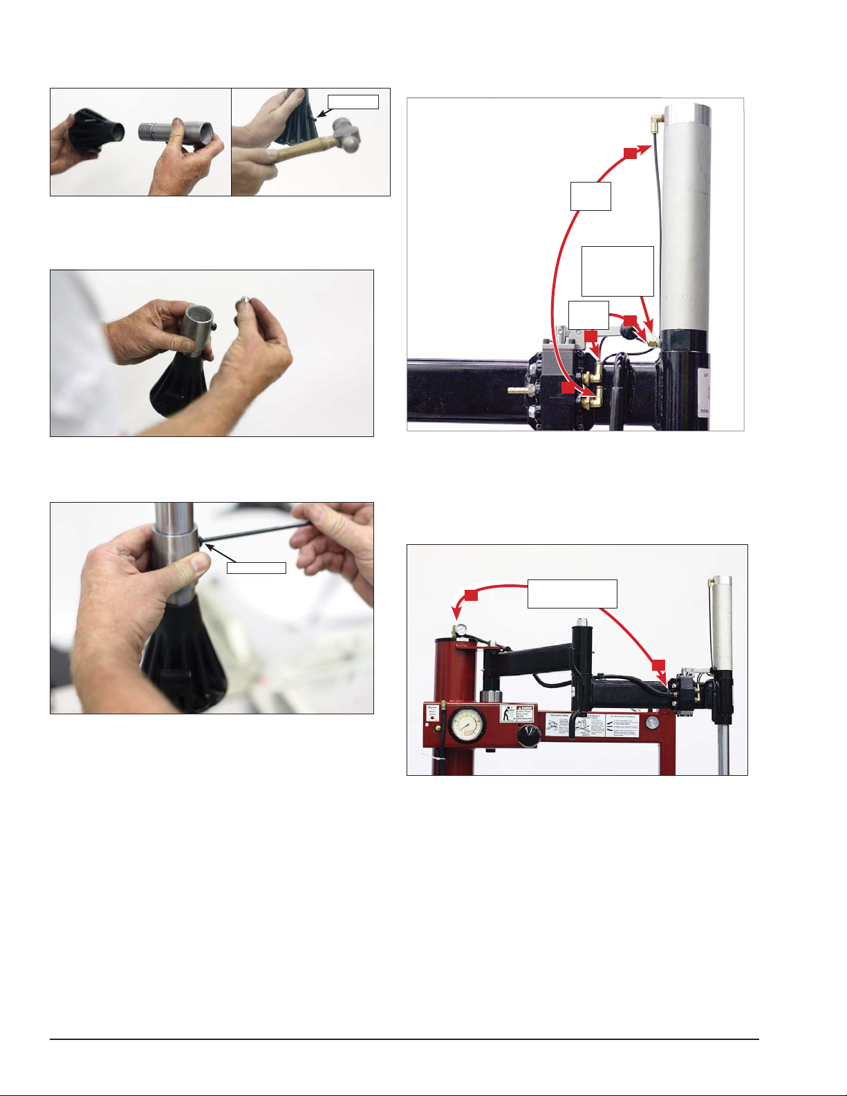
11. Next, install the helper tool onto the extender
shaft using the roll pin.
Roll Pin
Figure 11 - Install helper tool onto extender shaft.
12. Grease the steel ball and place it in the bottom
of the helper tool.
14. Connect 1/8-inch nylon tubes from robo cylinder
to cylinder arm valve fittings, as shown in figure 14.
Attach cable tie around tubes to bottom cylinder fitting.
A
Nylon
Tube
Use Cable
Tie To Nest
Tubing
Nylon
Tube
A
B
B
Figure 12 - Place greased ball in bottom of helper tool.
13. Install the helper tool on the cylinder shaft align-
ing it for set screw installation. Tighten the set screw.
Set Screw
Figure 13 - Install the helper tool on the cylinder shaft.
Figure 14 - Connect nylon tubes.
15. Attach hose clamps to arms. Next, unwrap the
hose from valve, guide through hose clamps; and, with
the hose pushed over the barbed fitting, tighten hose
clamps by pulling clamp tabs off.
C
Figure 15 - Route hose and tighten hose clamps.
Route and
Connect Hose
C
16. Next, reconnect the air pressure source and
check for leaks. Cycle the cylinder on the Robo-Arm™
LR several times to make sure cylinder operates correctly (valve up for cylinder up - valve down for cylinder
down).
4 • Tire Changers
Page 5

Operating Instructions
(with Robo-Arm™ LR)
This unit must be properly operated and properly maintained to help avoid accidents that could damage the
unit and injure the operator or bystanders. This section
of the Operating Instructions manual review basic operations and use of controls. These instructions should be
reviewed with all employees before they are allowed to
work with the machine. Keep these instructions near
the machine for easy reference.
Bead Loosening and Demounting
CAUTION
This machine may operate differently from
machines you have previously operated.
Practice with a regular steel wheel and tire
combination to familiarize yourself with the
machine’s operation and function.
A. Remember to remove all weights from both sides
of the wheel. Weights left on backside of wheel
may cause the wheel to be clamped unleveled.
This may result in the combination mount/demount
head contacting the rim causing scratches. On alloy
wheels, always rotate the wheel one turn after setting the Duckhead to insure proper wheel chucking.
B. Always review with the owner any nicks and
scratches on expensive wheel and tire combinations prior to servicing.
CAUTION
Loosening the beads on a partially or fully
inflated tire is unsafe and causes excess
movement and friction against the bumper
pads and excessive wear on pivots. Deflate
the tire completely to prolong the life of
your machine.
1. Deflate the tire completely by removing the valve
core from the valve stem (figure 1). Be cautious and do
not smoke as a flammable gas could have been introduced into the tire at some time.
Figure 1 - Remove Valve Core to Deflate Tire
CAUTION
Tires are always installed and removed from
the rim’s narrow side.
C. Always loosen the bead on the narrow side of
the wheel’s drop center first (tire removed in figure
2 for clarity).
Narrow Side
Drop Center
Long Side
Figure 2 - Determine Narrow Side of Wheel
E. The clamps on the table top may extend beyond
the table top itself. To avoid damaging the clamps,
move them to their full inward position before positioning a tire for bead loosening.
F. Use extra care in positioning the bead loosener
shoe on larger wheels/tires, and on alloy wheels.
Make sure the shoe rests next to but not on the
rim, and not on the tire sidewall.
Tire Changers • 5
Page 6

2. Pull the bead loosener shoe away from the machine
and roll wheel into position. The valve stem should be
in the 2 o’clock position to accommodate a possible
asymmetric safety hump type rim. Position the bead
loosener shoe against the tire next to, but not on, the
rim. Press the bead loosener foot pedal to actuate the
shoe and loosen the bead. It may be necessary to
loosen the bead in multiple locations around the tire
(figure 3).
Valve Stem
Figure 3 - Position Tire and Bead Loosener Shoe
4. Apply tire manufacturer’s approved rubber lubricant
liberally to entire circumference of both tire beads after
loosening (figure 5).
Figure 5 - Apply Rubber Lubricant to Tire Beads
5. Determine the mounting side of the wheel. The
mounting side is the narrow side of the drop center. See
figure 2 for more information on the drop center.
6. Place tire/wheel assembly on table top with mount-
ing side up (figure 6).
3. Turn the wheel around and repeat loosening pro-
cedure on the other side of the wheel (figure 4). This
should be the long side of the drop center (figure 2).
Figure 4 - Position Tire and Bead Loosener Shoe With Wheel
Turned Around
G. It will be easier to outside clamp the wheel to
the table top if the long side of the rim is loosened
last.
Figure 6 - Place Tire/Wheel Assembly on Table top
7. Use Robo-Arm LR with cone to apply pressure to
aid in clamping rim (figure 7). Use the clamp control
pedal to move the clamps inward (push pedal down)
or outward (toggle pedal up). Clamp steel wheels from
the inside (clamps push outward against wheel). Clamp
mag and custom wheels from the outside (clamps push
inward against the outside rim edge).
Figure 7 - Robo-Arm LR Aids Clamping
6 • Tire Changers
Page 7

8. Check helper foot positioning. Adjust helper foot
reach by rotating the extender up or down. Raise foot
for wide tires or lower foot for narrow tires.
Rotate
Rotate
11. Locate the valve stem just before the demount
head before proceeding (Figure 11).
Valve Stem
Raise For
Wide Tires
Lower For
Narrow Tires
Figure 8 - Using Helper Foot Extender
9. Depress the tire sidewall downward with the
aid of the helper foot providing clearance for the
mount/demount head to be positioned (figure 9). Move
swing arm into place. Increase the horizontal distance
between the demount head and the wheel an additional
1/16 to 1/8 inch with the adjustment knob.
Figure 9 - Helper Foot Depressing Sidewall of Tire
10. Lubricate upper bead liberally (Figure 10).
Demount Head
Figure 11 - Position Valve Stem Under Demount Head
12. Place helper foot opposite the demount head and
push the bead into drop center. Insert bead lifting tool
between knob on demount tool and tire bead (Fig. 12).
Figure 12 - Insert Bead Lifting Tool
13. Rotate lifting tool down over wheel to lift bead
up and over the knob and at the same time remove
helper foot.
14. Hold lifting tool in place, depress the table top
rotation pedal momentarily to jog the wheel a short
distance. Check the wheel and tire to verify that operation is not causing damage. The lifting tool can usually
be removed after jogging the wheel a short distance
(Figure 13). Continue to jog the wheel to allow the tire
sidewall to flex as it crosses the rim edge. Continue
short rotations until top bead is completely demounted.
Figure 10 - Lubricate Upper Bead
Figure 13 - Holding Lifting Tool in Place and Rotate Wheel
Tire Changers • 7
Page 8

15. Demount lower bead. Pay close attention to sen-
sor/transmitter location, and position it just before the
demount tool when starting the lower bead demount
procedure (Figure 14).
Sensor
Figure 14 - Sensor/Transmitter Location
16. Flip down the helper foot hook (figure 15).
Mounting
1. Lubricate both tire beads liberally. Performance
tires will require more lubrication than standard passenger car tires.
2. Mount the lower bead. In most cases, the lower
bead will mount easily.
AE: Mounting the top bead can be very difficult
when mounting new tires on performance and custom
wheels. Proceed slowly and cautiously.
3. Position the valve stem 90 degrees clockwise in
front of the mount/demount tool for top bead mounting. Lift the bead over the rear of the mounting head.
Use the helper tool to hold the bead in the drop center
(Figure 17). Rotate the wheel in short steps and apply
extra lubricant to mount upper bead.
Flip Hook
Down
Figure 15 - Using Helper Foot Hook
17. Position the helper foot hook to lift and hold the
tire at an angle so the lower bead is resting in the drop
center directly across from the demount head, and is
loose below the demount head. Insert bead lifting tool
down over demount tool and below the lower bead. Lift
the lower bead over the demount tool (Figure 13). Hold
the lifting tool in place. Depress the table top rotation
pedal momentarily to jog the wheel short distances to
complete the demounting process.
Valve
Figure 17 - Mount Upper Bead, Use Helper
4. On extremely tight tire and wheel combinations, it
may be necessary to use the bottom of the helper foot
to flip the tire bead over the rim flange (Figure 18)
Figure 18 - Helper Foot to Flip Bead Over Rim Flange
Figure 16 - Lower Bead in Drop Center
8 • Tire Changers
Page 9

Robo-Arm™ LR Maintenance
A. Grease the Robo-Arm LR to maintain smooth rota-
tion. Grease fittings have been provided at the pivot
joints.
B. Check bolt torque periodically at pivot joints. Proper
Torque is 240 ft. lbs.
Maintain Bolt Torque
at 240 ft. lbs.
Grease Fittings
Tire Changers • 9
Page 10

Parts Identifi cation
Kit 8560761701 Robo-Arm™ LR Accessory
32
8
36
14
15
9
35
18
34
14
22
23
10
38
7
6
11
17
24
13
39
16
33
21
5
12
19
25
4
41
2
1
3
42
43
44
ITEM PART NO. DESCRIPTION
1 85607622 Plastic Hold Down Foot
2 905563 Roll Pin, 1/4" Dia x 1-1/2"
3 8301017 Dia. Steel Ball, 1/2"
4 7000230 Rubber Hand Grip, 1/2"
5 8183637 2" Ext. Retaining Ring
6 8181983 10-24 x 3/4 Lg. BHSCS
7 *** Robo-Arm LR Valve Assembly
8 85607946 Cyl Assem 2" Dia x 8-inch Stroke
9 8181996 1/4 NPT x 1/8 Tube St. Fitting
10 8106301 1/4-20 x 3/4" HWHST Screw
11 8182044 Neoprene Cushion Clamp
12 8183649 1/4-20 x 5/16" Soc Hd Set Screw
13 8184226 1/4-28 Grease Fitting
14 8182016 3/4-10 Hex Nylock Lock Nut
15 8100994 Flat Washer, 3/4"
16 85607618 Front Arm Weldment
17 85607619 Rear Arm Weldment
18 8181038 Swing Arm Pivot Pin
19 8183703 3/4-10 x 10-1/2” Hex HD Cap Srw
21 8182457 Flat Washer, 3/4 SAE
Torque To
Torque To
240 ft./lb.
240 ft./lb.
ITEM PART NO. DESCRIPTION
22 8108968 Air Gauge
23 8182599 Safety Valve
24 8000378 1/4" Brass St. Fitting
25 8183635 Screw, 3/4-10 x 14, HHCS, Gr.5
32 8181997 90º Elbow
33 8184208 Pivot Pin Spacer
34 * Hose, Rubber, 1/4, 58" Black
35 * Plastic Tube, 1/8 x 6"
36 * Plastic Tube, 1/8 x 16"
38 Wire Tie
39 8184059 Manifold Assembly
41 85607692 Extender w/Set Screw
42 8100602 3/16 x 1-1/4 Roll Pin
43 85607688 Plastic Hold Down Foot Hook
44 85607680 Cone
* Hose Reels
LENGTH PART NO. DESCRIPTION
50-ft. 85000375 1/4” ID x 1/2” OD Black Rubber Hose
50-ft. 85000376 1/8” OD x 0.25 Plastic Tube
10 • Tire Changers
Page 11

3
2
1
4
5
3
2
1
4
5
7
45
1
46
2
47
3
48
4
49
5
Robo-Arm LR
ROBO ARM ASSEMBLY VALVE
Assy Valve
ITEM PART NO. DESCRIPTION
45 8000378 Brass Straight Fitting, 1/4 NPT
46 8105615 Small Muffler
47 8185585 3 Position Valve
48 8109481 RDCR Fitting, 1/4 NPT x 1/8 NPT
49 8181997 Male Elbow, 1/8 NPT x 1/8"
Tire Changers • 11
Page 12

8560762401 01 02/12 © Copyright 2011 Hennessy Industries and COATS All Rights Reserved
 Loading...