

Page 1

Leverless Bead Lifter
Kit 85606689
For use with COATS Tire Changers
This is a supplement to your operating manual and covers the installation and use of the COATS® Leverless
Bead Lifter. If you do not have your original operating manual, please call COATS at 1-800-688-6359 to request
an additional copy.
User Instructions
with Parts Identifi cation
READ these instructions before placing unit in
service. KEEP these and other materials delivered
with the unit in a binder near the machine for ease
of reference by supervisors and operators.
1601 J. P. Hennessy Drive, LaVergne, TN USA 37086-3565 615/641-7533 800/688/6359 www.ammcoats.com Manual Part No.: 85606701 00
HENNESSY INDUSTRIES INC. Manufacturer of AMMCO
®
, COATS® and BADA® Automotive Service Equipment and Tools. Revision: 07/10
Page 2

Qualifying Test For
Machine Compatibility
1. Push down on mount/demount head while pulling
up on table top. Record distance — top of clamp to
bottom of mount/demount head.
2. Now, pull up on mount/demount head while push-
ing down on table top. Record distance — top of clamp
to bottom of mount/demount head.
3. Subtract step 1 distance from step 2 distance. If
distance is greater than 3/8-inch then machine is not
compatible.
Note: If the machine is not compatible, please con-
tact COATS® at 1-800-688-9240 for the Certified Service Partner nearest you.
2 • Important: Always read and follow the instructions.
Page 3
Leverless Bead Lifter
Installation
CAUTION
Always DISCONNECT THE ELECTRICAL
POWER before servicing equipment. This
prevents electrical shock or accidental
movement of the systems operated by the
electrical power.
CAUTION
Always DISCONNECT AIR SUPPLY before
servicing equipment. This prevents accidental movement of systems operated by compressed air which may result in personal
injury. BLEED THE AIR SYSTEM by actuating
all the valves.
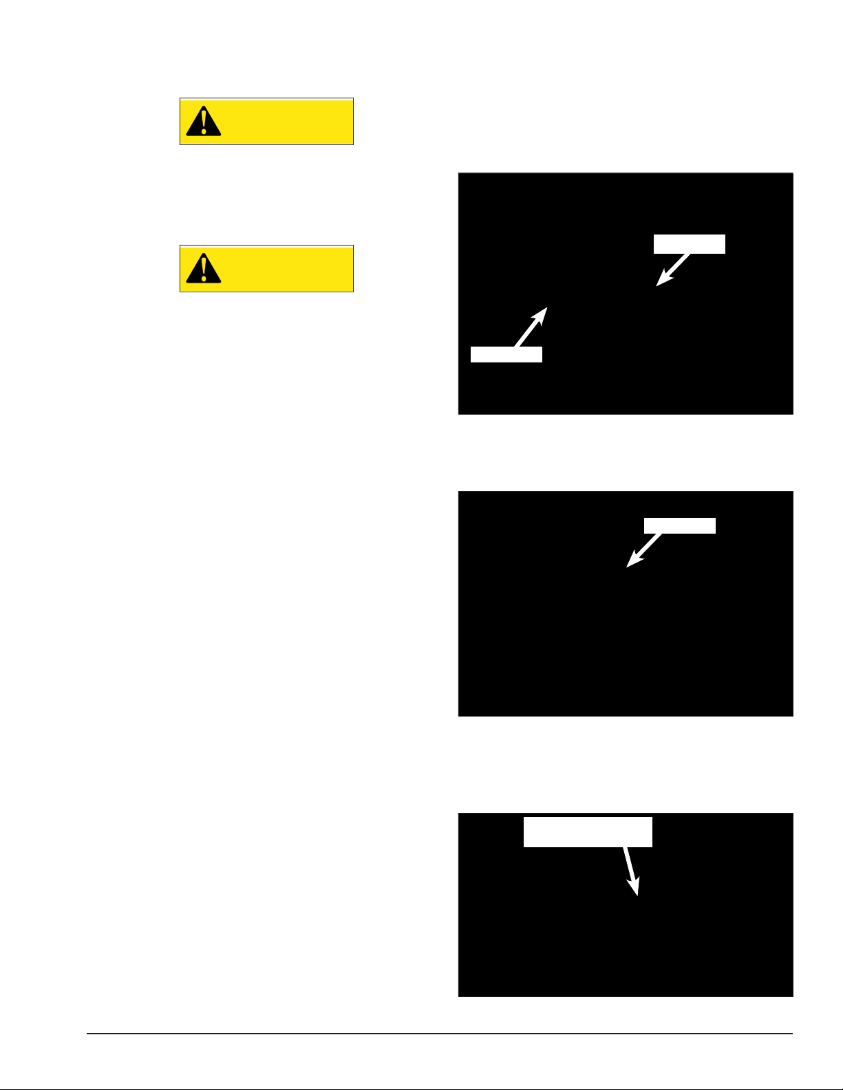
50/70x Series Installation
1. Disconnect the electrical power and air supply
from the machine; empty all residual air.
2. Remove side panel from chassis.
3. Locate and cut rubber hose that is between the
pedal valve and oil injector.
Pedal Valve
Oil Injector
4. Route kit hose assembly through 1-inch hole in
rear of chassis. Place hose clamps on cut hoses, then
connect rubber hoses (from step 3) to tee fitting on kit
hose assembly.
Tee Fitting
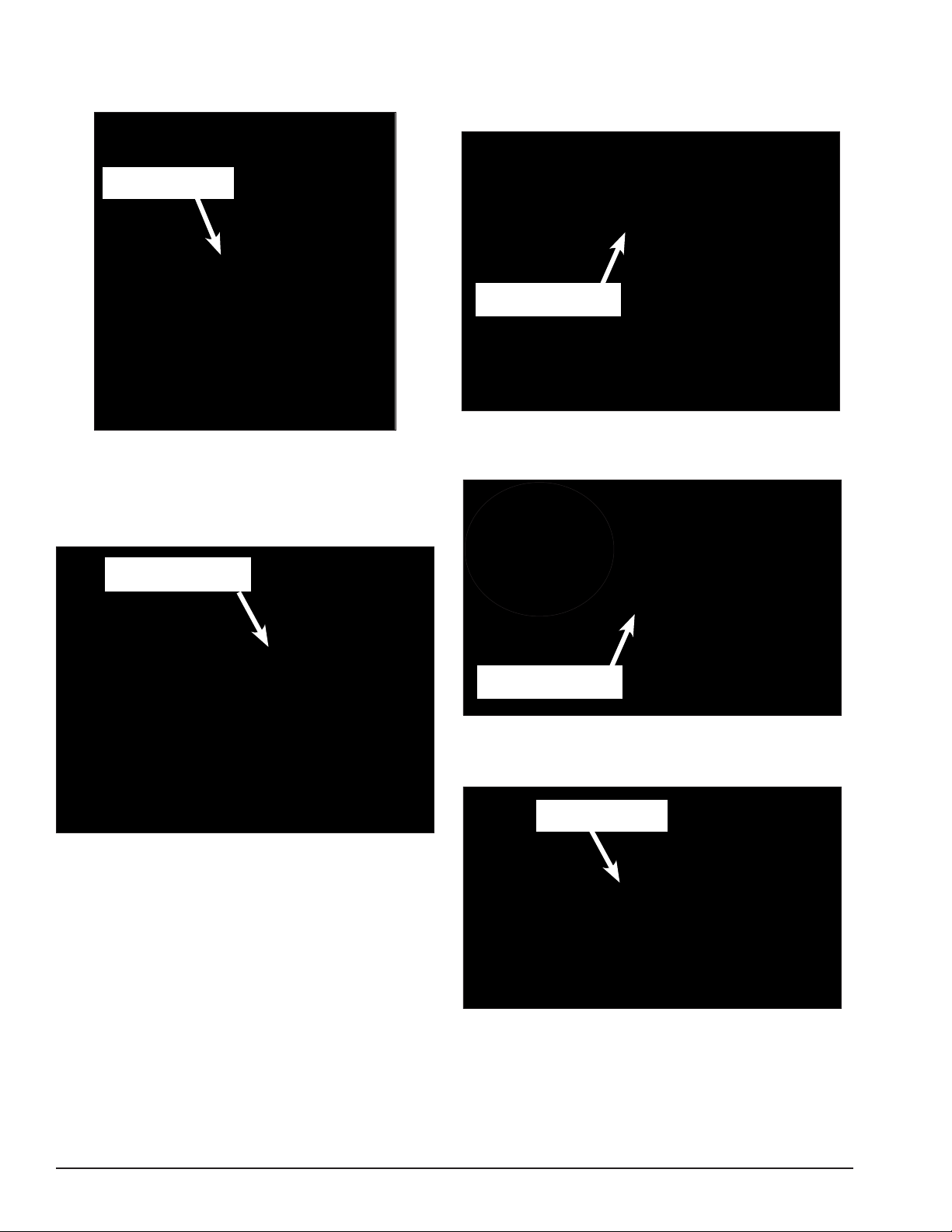
5. Route kit hose up the back of the tower. Install
cushion hose clamp around air hose near the fitting.
Then, fasten clamp/hose assembly to top of swing arm
using supplied bolt (or use a self-supplied 1/4-inch selftapping screw).
Fa s ten Hos e To Top
Of Swing Arm
Important: Always read and follow the instructions. • 3
Page 4
6. Lock the vertical slide shaft and then remove the
mount/demount head, Duckhead® roller mount and
rubber cushion.
Remove Mount/
Demount Head
7. Hold vertical slide shaft down, release lock handle
and remove shaft assembly out the top. Note orientation of flat on the end of shaft.
Note: On units equipped with shoulder screw, use
shim for plastic mount/demount head vertical bar lock.
10. Attach adapter to leverless bead lifter mount/
demount head so that the (2) set screws line up with
the adapter flat. Snug (1) set screw on side to hold
adapter in place.
Align Set Screws
With Adapter Flat
11. Assemble washer set on screw, small washer
first with mating bevels together. Attach leverless bead
lifter assembly to vertical shaft; hand-tight only.
Hold Shaft Down
And Release Lock
8. Remove spring, install short spring from kit and
place shaft assembly back into swing arm. Reassemble
with shaft flat in same orientation.
9. Lock shaft.
Attach Leverless
Bead Lifter To Shaft
12. Connect coil air hose from leverless bead lifter to
the fitting installed on top of swing arm bracket (from
step 5).
Connect Coil Hose
To F itti ng
13. Re-connect air supply to machine. Inspect and
correct leaks if found.
14. Be sure to perform the steps for the Leverless
Bead Lifter Adjustment Procedure on page 7.
4 • Important: Always read and follow the instructions.
Page 5

APX Series Installation
1. Tilt tower forward and rotate slide shaft control to
the DOWN position. Do not lock.
2. Disconnect power and air; empty all residual air.
3. Remove the mount/demount head and rubber
bumper.
4. Remove the screw from top of vertical slide cap.
5. Remove rubber stop and hardware from vertical
shaft.
10. Place air coil hose through hole in tower bracket.
Route Coil Hose
Through Hole In
Bracket
Remove Hardware
From Vertical Shaft
6. Slide vertical shaft out the top and rotate it 180
degrees; then re-insert the vertical shaft.
7. Place spring over top of vertical shaft.
8. Replace screw (from step 5) in top cap.
Replace
Screw
11. Cut 1/8-inch tube as shown.
Cut Tubing
12. Assemble (2) cut ends to tee supplied with kit
and push-connect coil hose to tee fitting.
Install Tee
Fitting
Connect Coil
Hose
9. Attach adapter to the leverless bead lifter and
install the assembly to the shaft following the 50/70
series installation steps 10 & 11.
13. Re-connect air supply to machine. Inspect and
correct leaks if found.
14. Be sure to perform the steps for the Leverless
Bead Lifter Adjustment Procedure on page 7.
Important: Always read and follow the instructions. • 5
Page 6

9024 Series Installation
1. Lower vertical slide shaft about 9-inches. and lock
bar. Tighten hex screw to lock bar.
2. Disconnect the electrical power, close the air lever
cock and bleed the air circuit completely.
3. Release hex screw of pipe locking knob. Insert kit
spring and hex washer and tighten hex screw back on.
6. Insert the other end of the hose into the T-union
previously installed (step 4).
7. Using two hose clamps from kit, attach the hose
at the end of the guide placed behind the post. Cut the
over length and secure with ties.
Use Hose
Clamps To
Route Hose
4. Cut the black hose, as in picture, and insert the
union delivered with the kit.
Install
Union
5. Place the plate, complete with unions, on the
locking plate screw. Attach nut and tighten. Then insert
hose into the L-shaped union.
Attach Plate
8. Remove the mount/demount head. Then release
the tool locking screw using hex wrench. Keep screw
and washers.
9. Next install the leverless bead lifter to the shaft
following the 50/70 series installation step 11.
10. Insert the quick union into the free end of the
coil hose and then insert this quick union into the
female union on the plate (from step 5).
11. Re-connect air supply to machine. Inspect and
correct leaks if found. Open the air lever cock to send
pressure to circuit.
12. Move the bar lock selector to middle position.
You will hear an air bleed.
13. Release the hex bush screw to release the oper-
ating arm.
14. Be sure to perform the steps for the Leverless
Bead Lifter Adjustment Procedure on page 7.
6 • Important: Always read and follow the instructions.
Page 7

Leverless Bead Lifter
Adjustment Procedure
1. Use a 17-inch diameter wheel for adjustments.
This covers the normal range of 14 to 21-inch wheels.
2. Set mount/demount head to 1/8 to 3/16-inch
above wheel.
1/8" to 3/16"
5. Loosen (2) set screws on adapter 1/4 turn.
6. Tighten screw holding leverless bead lifter assem-
bly to vertical shaft; torque to 20-26 ft-lbs.
Torq ue To
20-26 ft-lbs.
7. Tighten set screws (4) — (2) on adapter and (2) on
mount/demount head.
8. Tighten (1) set screw on side of mount/demount
head
3. Align mount/demount head to match curvature of
wheel.
Align Mount/
Demount Head
With Wheel
Curature
4. Snug (2) set screws in adapter. Then snug (2) set
screws in mount/demount head making sure mount/
demount head to wheel relationship doesn’t change.
9. Tighten (1) set screw through access hole on
leverless bead lifter.
Tighten Set
Screw
(2) Adapter
Set Screws
(2) Mount/Demount
Head Set Screws
Important: Always read and follow the instructions. • 7
Page 8

Leverless Bead Lifter
Operation
This accessory is normally used in the servicing of
single piece automotive and most light truck tire/wheel
assemblies.
Demounting
Follow tire changer operating instructions provided
for demounting a standard wheel assembly, except:
1. After deflating and bead loosening, clamp the
wheel to the table top. Position leverless arm until
mount/demount head plastic contacts wheel.
3. Tighten swing arm adjustment screw until it con-
tacts arm.
4. Lube leverless tool.
7. Push control handle up, retracting leverless tool.
Note: Use helper arms if equipped.
8. Rotate tire to remove top bead.
9. Position valve stem as shown in step 5.
10. Repeat #6
Note: To aid bead lubing, lower leverless tool slightly
to move bead away from wheel.
5. Position valve stem approximately as shown to
prevent damage to TPMS (Tire Pressure Monitoring
System) sensor.
6. Push control handle down to lower leverless tool
under tire bead while pulling leverless handle to hold
leverless bead lifter against the wheel.
Note: If leverless tool does not hook under tire bead,
reverse rotation. Re-position valve stem while pushing
bead opposite leverless bead lifter into drop center.
11. While holding tire up into drop center, lift tire to
hook the bead on leverless tool, push control handle up
to lift bead over rim.
12. Rotate to remove tire.
8 • Important: Always read and follow the instructions.
Page 9

Mounting
13. Lube beads.
14. Place tire on wheel.
15. Position leverless bead lifter arm so tire bead is
above tail of mount/demount head and position valve
stem just in front of where bead crosses rim.
Valve
Stem
16. Rotate wheel to mount lower bead.
17. To mount top bead, position valve stem just in
front of where bead crosses rim and be sure the tire is
on top or the mount/demount head tail.
18. Slightly lower leverless tool to push bead down;
hold opposite side of tire down into drop-center.
Valve
Stem
19. Rotate wheel to mount upper bead.
20. Inflate, unclamp per standard instructions.
Important: Always read and follow the instructions. • 9
Page 10

Parts Identifi cation
Leverless Bead Lifter
Item No Part No. Description
1 84297851 Handle
2 87019215 Valve Box
3 84399954 Screw 8x20
4 84395374 Nut M8
5 83030571 Spiral Hose 6x4, L=1500
6 84198285 5-way Valve
7 82006996 Valve
8 84198618 Union 1/8"
9 84399829 Washer 8 (8, 4x16x1,5)
10 84399900 Self-locking Nut M8
11 84393957 Screw 10x12
12 84399864 Seeger Ring D.12
13 84395530 Screw 12x2
14 84395529 Screw 12x16
15 83019305 Back Slide
16 83019198 Touchless Mounting Tool
17 84299720 Clamp 188x4,5
18 83019202 Connection Plate
19 84399434 Screw 12x20
20 84398637 Washer ID 12x21x2,5
21 83017334 Bush 12/18/8,2
Item No Part No. Description
22 83017302 Ferrule 12/18/6,5
23 83019212 Tool Pin
24 83019214 Connection Rod
25 84393753 Screw 5x8
26 83019306 Tool Front Slide
27 83019210 Pin
28 83019213 Touchless Tool
29 83010284 Knob D.14x45 M5
30 83019211 Cylinder Pin
31 83019561 Support Plate
32 84194004 Union MR 41 6 M6
33 84199161 Plug 1/8"
34 84199610 Silencer 1/8"
35 84399957 Screw 6x8
36 82031707 Cylinder Unit
37 84399976 Nut M8
38 84298822 O-ring D.68, 26x3, 53
39 84399865 Self-locking Nut M12
40 84198856 Piston D.75
41 83031708 Cylinder Shaft
10 • Important: Always read and follow the instructions.
Page 11

Item No Part No. Description
42 83019208 Special Screw 8x1, 25x180
43 83019204 Special Screw M8X1, 25x164
44 83031709 Cylinder Liner L=125
45 83015024 Flange
46 83199601 Scraper
47 83019467 Back Flange D.75 SO Side Hole
M6
48 87019199 Tool Holder
49 83019959 Hose 6x6 L=240
51 84396878 Steel Shim 12x25x0,5
52 83031595 Threaded Tab
53 83032778 Hose D.6x12 L=7,5 Ft (2300mm)
54 83031235 Spring
55 84397560 Screw 5x16
56 84399292 Washer 5 (5,3x10x1)
57 84398987 Self-locking Nut M5
58 84193590 Hose Clamp 15x15
59 84197390 Clamp D.8x13 H9
60 84199026 Union
61 84198894 Coupling 1/4"
62 84198298 Quick Union 1/4"
63 84193591 Clamp D.16 with Nut
Item No Part No. Description
64 84193592 Coupling 10-1/4
65 84198630 Union 1/4”
66 83030807 Adapter
67 84395804 Washer G Type 14,2x35x5
68 84395805 Washer C Type 10, 2x21x4
69 84393850 Screw 3/8”-16 L=2,5” UNC
70 83030792 Balance Spring
71 83019471 Washer
72 84399967 Nut M10
73 84194089 Quick Union Mod.5053-1/8 F
74 83019607 Quick Fastening Plate
75 84198618 Union 1/8"
76 84194088 Quick Union
77 84198993 Quick Union 1/8"
78 83019962 Hose 6x4 Black L=1500
79 84198172 Connection
80 84198778 Quick Union 1/8"
81 84193574 Straight Union S 6510 6-18
82 84193577 T-Union TT200 1/8
83 84193575 Reduction 1/8 M5
84 84193576 Straight Union M5
70X Series
9024 Series
APX Series
Important: Always read and follow the instructions. • 11
Page 12

85606701 00 07/10 © Copyright 2010 Hennessy Industries and COATS All Rights Reserved Printed in USA
 Loading...