

Page 1
1601 J. P. Hennessy Drive, LaVergne, TN USA 37086 615/641-7533 800/688-6359 Manual Part No.: 85000695 00
HENNESSY INDUSTRIES INC. Manufacturer of AMMCO
®
, COATS®and BADA®Automotive Service Equipment and Tools. Revision: 07/07
RoboRoller™ Arm Kit 85000497
For use with COATS Model APX Series Tire Changers
®
Installation Instructions
with Parts Identification
READ these instructions before placing unit in
service KEEP these and other materials delivered
with the unit in a binder near the machine for
ease of reference by supervisors and operators.
This is a supplement to your operating manual and covers the installation of the RoboRoller™. If you do not have
your original operating manual, please call COATS at 1-800-688-6359 to request an additional copy.
Page 2
2 • COATS RoboRoller™ Assembly
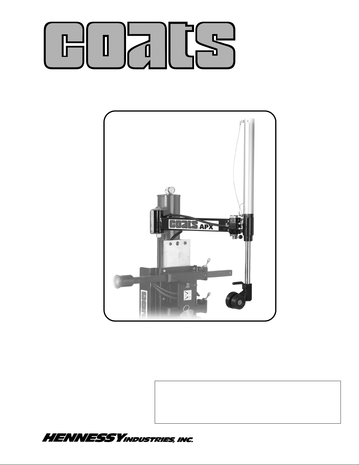
Assembly Instructions
Item Description
1 Cylinder Assembly
2 Socket Head Set Screw
3 Retaining Ring
4 1/2-Inch Dia Ball Bearing
5 Robo Roller Arm
6 Roller Assembly
7 3/8-16 x 1/2 Soc Set Screw
8 Pivot Pin
1. Install the ball bearing (4) inside the top of the
roller assembly (6). Apply grease to the ball bearing.
2. Slide the cylinder assembly (1) through the
RoboRoller arm (5) shaft, as shown. Then install the
retaining ring (3) into cylinder retaining ring groove.
3. Using the supplied set screw (7), install the roller
assembly (6) on the cylinder assembly, as shown.
Advance the set screw until it touches the bottom
groove of the cylinder’s pistion rod. Then back it off just
enough to allow the
roller assembly to pivot
freely.
Note: Use a drop of
non-hardening Loctite
on the set screw.
4. Next, install and
tighten RoboRoller arm
set screw (2) to lock
cylinder assembly into
place.
Installation Instructions
Always DISCONNECT THE ELECTRICAL
POWER before servicing equipment. This
prevents electrical shock or accidental
movement of the systems operated by the
electrical power.
Always DISCONNECT AIR SUPPLY before
servicing equipment. This prevents accidental movement of systems operated by compressed air which may result in personal
injury. BLEED THE AIR SYSTEM by actuating
all the valves.
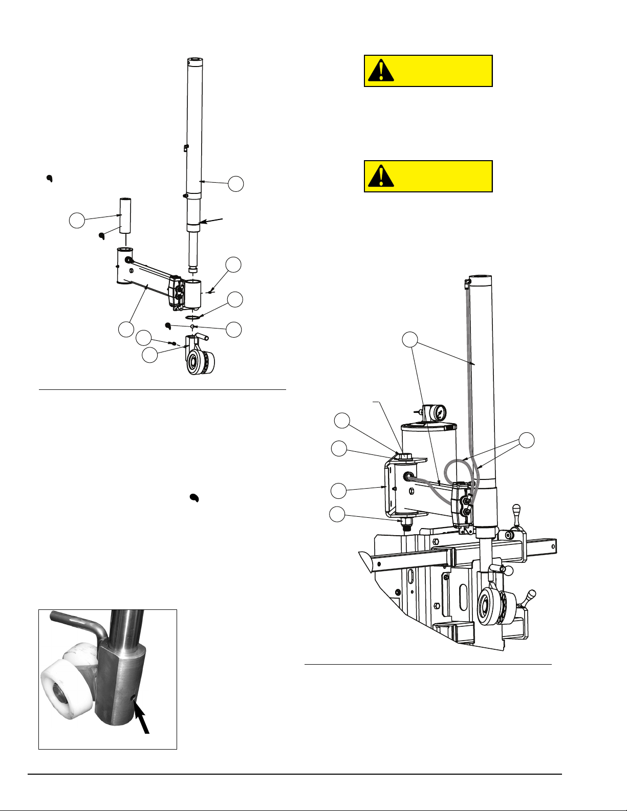
Item Description
9 RoboRoller Arm Assembly
10 10 3/4-inch Long Bolt
11 810 ID x 1-1/2 OD Washer
12 Trim Strip
13 3/4-10 Hex Lock Nut
14 1/8-inch OD x 0.25 Plastic Tubing, 6-inches
1/8-inch OD x 0.25 Plastic Tubing, 27-inches
CAUTION
CAUTION
2
3
7
4
1
5
8
6
Apply Grease To These Locations
Set Screw (7)
Retaining
Ring Groove
Assemble RoboRoller
arm before attaching to
the machine
10
11
12
13
9
14
TORQUE TO 240 ft. / lb.
Page 3

COATS RoboRoller™ Assembly • 3
1. Before beginning any work, clear the area and
position machine for easy access. Disconnect all
power sources, both air and electricity inputs. Allow
any stored air in the reservoir to escape by depressing
the inflate pedal.
2. Verify the stored air pressure is zero by observing
the air pressure gauge on top of the tower.
3. Install RoboRoller arm assembly onto tower arm
pivot system bracket. Place a washer (11) on the head
of the 10-3/4 inch long bolt (10). Position RoboRoller
arm assembly (9) with pivot pin (8) spacer on the pivot
bracket, hold assembly and push long bolt with washer
through the top side of bracket. Next, place a washer
(11) and the lock nut (13) on the long bolt. Place the
trim strip (12) on the pivot bracket.
Note: Be sure to apply grease to the pivot pin.
4. Next, using large wrenches, tighten the assembly
to 240 ft. pounds torque (very tight). Even though the
bolt is very tight, the assembly should rotate easy.
5. Locate the two pieces of plasitc tubing (14); con-
nect each from the valve to the cylinder, respectively
(as shown in diagram).
Push one end of the 6-inch tubing into valve’s top selfconnect fitting; then route and push other end into
cylinder’s bottom self-connect fitting. Next, push one
end of the 27-inch tubing into valve’s bottom self-connect fitting; then route and push other end into cylinder’s top self-connect fitting.
6. Connect the rubber hose (16) from the arm valve
to the air manifold. Before routing hose, remove tower
auxillary cover and the chassis side panel. Refer to the
diagrams on this page.
First push hose end over arm valve’s barbed fitting
(see back of arm view) and tighten the screw type
hose clamp (17). Then guide hose through clamp, on
arm; route around tower and down behind the vertical
slide plate tower bracket. Now, continue to guide the
hose into hole on tower support and through hole into
chassis.
Remove the plug from air manifold and replace with
straight fitting (15). Push hose end over straight fitting
and tighten the screw type hose clamp (17). Replace
tower auxillary cover and chassis side panel.
7. Next, reconnect the air pressure source and check
for leaks. Cycle the cylinder on the RoboRoller™ several times to understand function.
Item Description
15 1/4 NPT Straight Fitting
16 1/4 x 137-inch Rubber Hose
17 1/4-inch Hose Clamp
15
17
16
Back Of Arm Detail View
9
16
15
17
Page 4

85000695 07/07 © Copyright 2007 Hennessy Industries and COATS All Rights Reserved Printed in USA
2 2
3 3
8 8
9 9
1 1
4 4
5 5
6 6
7 7
10 10
11 11
12 12
20 20
13 13
14 14
15 15
16 16
17 17
18 18
19 19
21 21
22 22
23 23
24 24
ROBOROLLER PARTS IDENTIFICATION
ITEM PART NO. DESCRIPTION
1 8185593 ROLLER,SMALL,AUX ARM
2 8185597 HOUSING/BRACKET W/C
3 8180217 5/16-18 x 3/8”” SET SCREW
4 7000230 GRIP-HANDLE
5 8185594 SHAFT - AUX ROLLER
6 8185592 ROLLER,LARGE,AUX ARM
7 8100964 RING - RETAINING 1 1/4
8 8181983 SCREW - 10-24 x .75, BHSCS
9 *** VALVE-3POS
10 8181996 ST. MALE FTG, 1/8 NPT X 1/8
11 8181997 FITTING
12 8183644 CYLINDER-SPECIAL
13 8106301 SCREW-HEX WASHER HEAS
14 8182044 CLAMP - NEOPRENE CUSHION
15 8184226 FITTING - GREASE 1/4 -28
16 8181038 PIN-PVT.ARM,SWNG
17 8185601 BUMPER-3/4ID
18 8184941 WELDMENT - AUX,ARM
19 8183649 SOCKET HD. SET SCREW
20 8183637 RING -RETAINING
21 8301017 BA L L 1 /2
22 8130026 3/8-16 x 1/2 SOC
23 8181137 SCREW, 3/8-16x2-1/4 HEX HD CAP
24 8185539 STOP-BLOCK AUX ARM
APPLY GREASE TO THESE LOCATIONS
*** See RoboRoller Assy Valve
3 3
2 2
1 1
4 4
5 5
ROBO ROLLER ASSY VALVE
ITEM PART NO. DESCRIPTION
1 8181997 MALE ELBOW, 1/8 NPT X 1/8 (K)
2 8109481 FITTING-RDCR,1/4NPT X 1/8NPT
3 8185586 VALVE-3POS
4 8105615 SMALL MUFFLER
5 8000378 FITTING-STRGHT,1/4NPT,BRSS
 Loading...