

Page 1
111864
COATS
Motorcycle Wheel
Adapter Kit
Installation and Operation Instructions
with Parts Listing
P.O. Box 3002, 1601 J.P. Hennessy Drive, LaVergne, TN 37086 U.S.A. 615/641-7533 800/688/6359
HENNESSY INDUSTRIES, INC. Manufacturer of AMMCO®, COATS®, and BADA®Automotive Service Equipment and Tools
111865 11/97
Page 2
Installation and Operation
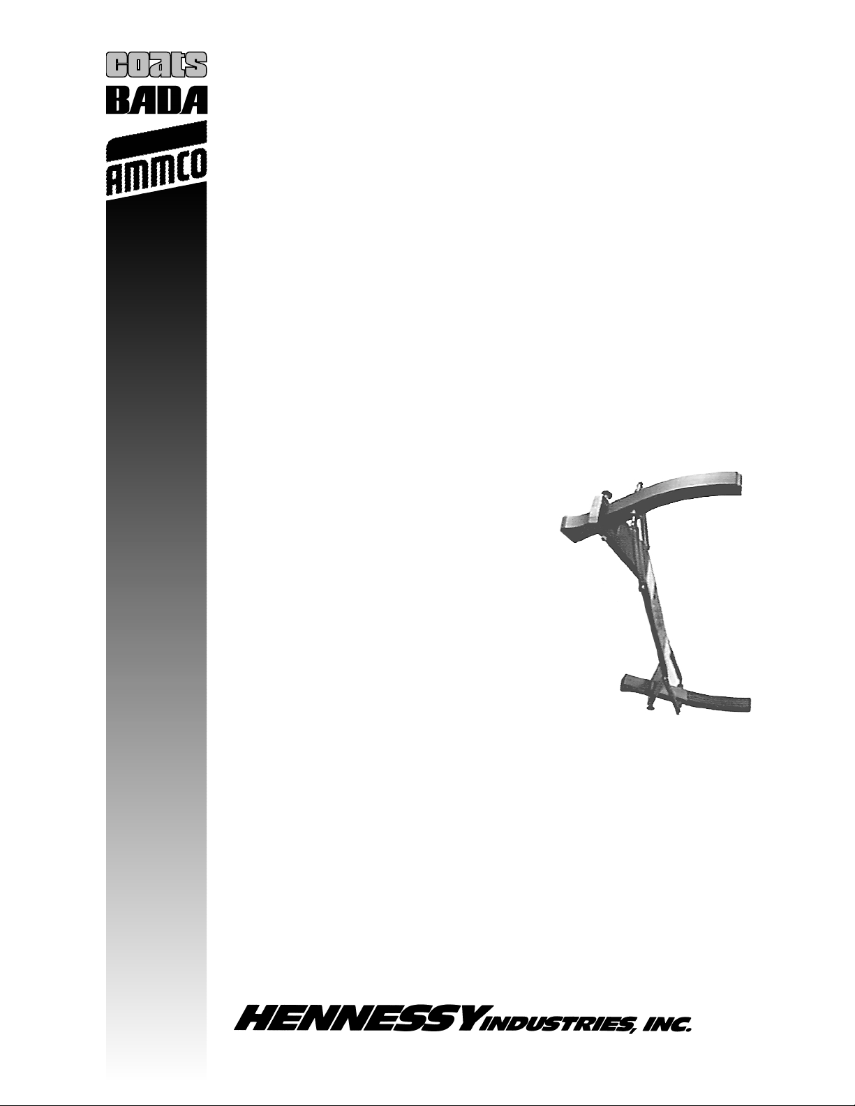
Installing the Jaw Drive Bar and Spindle
1. If equipped, remove the threaded stub shaft
from the balancer using a 3/4” wrench.
2. Make sure the faceplate and motor shaft are
clean, then place the jaw drive bar onto the
motor shaft and secure it to the faceplate with
the 3/8-16 socket cap screws provided.
Tighten the screws.
Figure 1 – Jaw Drive Bar Mounted to Balancer
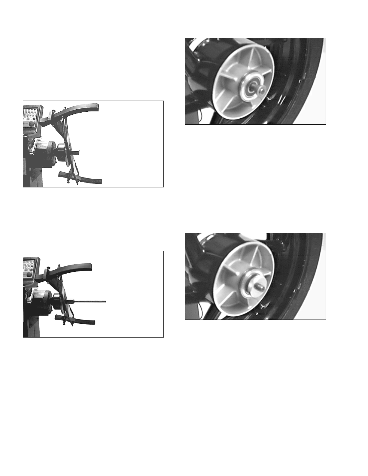
3. Clean the threads and mating surfaces on the
end of the motor shaft where the threaded
stub shaft or motorcycle spindle will be
installed.
4. Thread the 14mm spindle into the motor shaft
and tighten with the provided hex wrench.
Figure 2 – Spindle Added to Motor Shaft
Mounting a Motorcycle Wheel
Always try to use the stepped bearing adapters
when mounting wheels. Use the tapered cones
only if none of the stepped adapters provides an
exact fit into the wheel bearings.
1. If the wheel and drive assembly is too wide to
fit on the spindle, remove any sprocket or
drive shaft cushion hubs. Remove any axle
spacers if they came off the axle with the
wheel.
2. Find the stepped adapter or tapered cone that
best fits the wheel.
Figure 3 – Find the Appropriate Stepped Adapter or
Tapered Cone
3. Slide the adapter or cone onto the spindle,
large end first.
4. Slide the wheel onto the spindle and guide it
over the previously installed adapter or cone.
5. Slide the other matching adapter or cone onto
the spindle and into the wheel bearing.
6. Slide the spacers onto the spindle as
necessary so the spindle nut can be
tightened. Install the spindle nut and tighten
by hand only.
Figure 4 – Add Spacers then Spindle Nut
7. Rotate the adapter so that one of the lock jaws
is facing the front of the balancer. Lift the
stopper from its holding position and allow
the lock jaw to come into contact with the
wheel.
8. Repeat step 7 for the other lock jaw.
Page 3

Figure 5 – Wheel Installed, Before Jaw Contact
Figure 6 – Jaws in Contact with Wheel
Use caution to avoid
personal injury. The
springs pulling the
lock jaws towards the wheel are very stiff.
Balancing Motorcycle Wheels
IMPORTANT: If the balancer being used does not
have a hood, use caution when balancing the
wheel. Always wear eye protection and keep
bystanders away. Do not attempt to stop the
wheel manually. Wait for the balancer to brake
the wheel to a complete stop before contacting
the wheel.
REMEMBER: This instruction sheet is intended to
supplement your COATS Wheel Balancer
Operating Instructions manual. It does not
replace the manual. Read and understand the
entire manual before attempting to use the
balancer.
1. Turn the balancer on and select STATIC mode
balancing. Remove any weights on the wheel.
NOTE: In STATIC mode, the wheel width and
offset values are not used by the balancer’s
computer. However, a value must be entered
for these parameters so that the balancer will
operate properly. Steps 3 and 4 will direct you
to manually enter the measurements.
2. Press the diameter key and enter the wheel
diameter. For example, press 1 then 8 then 0
to enter a wheel diameter of 18 inches.
3. Press the offset key, then press 6 and then 0.
You have entered an offset of 6.0.
4. Press the wheel width key, then press 6 and
then 0. You have entered a wheel width of 6.0.
5. Press START. Wait for the wheel to spin and
brake to a complete stop. Readings will
appear in the display.
6. Rotate the wheel until the left weight position
lights flash.
7. Attach the specified weight at top-dead-center
by one of the following methods:
Wire Spokes: Clip the weight onto the spoke
nearest to top-dead-center, or use 2 weights
that are 1/2 the specified amount, and place
them on the 2 spokes on either side of topdead-center. An adhesive weight can be used
if placed directly on the middle of the rim.
Cast or Composite Wheels: If the wheel has a
center rib and factory clip weights (Honda, for
example), attach the weight over the rib. If the
wheel has a center rib and adhesive weights
are being used, divide the weight in half and
place on either side of the rib. An alternate
method is to bend the weight in half over the
center rib.
8. Press START. The display should now read
0.00 (in non-round-off mode).
9. Remove the wheel. If you are balancing
another wheel identical to this one, you do
not need to remeasure the wheel or reset the
measurements. Simply mount the next
wheel, remove any weights, and press START.
CAUTION
!
Page 4

Parts Listing
ITEM PART NO. QTY DESCRIPTION
1 111779 1 Jaw Connector
2 111778 4 Spring
3 111777 4 Screw, M8x25
4 111 776 4 L ock Nu t
5 111775 2 Screw, M6x70
6 111774 2 Stopper
7 111773 2 Lock Jaw
8 111780 2 Screw, TSEI, M8x25
9 111781 1 Key, Hexagonal, 15mm
10 111782 1 Long Hub, 28.5
11 111863 2 Screw, VTCEI, M6x18
12 111783 1 Wheel Holding Shaft
13 111784 2 Centering Cone
14 111785 1 Bushing, 17x14mm
15 111786 2 Spacer
16 111781 1 Collet for Shaft
17 111789 2 Bushing - BMW Wheels
18 111790 1 Bushing, 20x14mm
19 111791 1 Bushing, 25x14mm
20 111792 2 Cone - BMW Wheels
111865 11/97 ©COPYRIGHT 1997 HENNESSY INDUSTRIES AND COATS ALL RIGHTS RESERVED PRINTED IN U.S.A.
 Loading...