

Page 1
8110585 02 06/09 1 of 4 © COPYRIGHT 1991 HENNESSY INDUSTRIES AND COATS ALL RIGHTS RESERVED PRINTED IN U.S.A.
Pressure Limiter Kit 8110584
Installation Instructions & Parts List
for RC-15A, RC-15AA, RC-20A, RC-20AA
& 40-40 Tire Changers
Hennessy Industries • 1601 J.P. Hennessy Drive, LaVergne, TN 37086-3565 (800) 688-6359 • (615) 641-7533 • (615) 641-5104 FAX • www.ammcoats.com
Installation Instructions
Always DISCONNECT THE ELECTRICAL
POWER before servicing equipment. This
prevents electrical shock or accidental
movement of the systems operated by the
electrical power.
Always DISCONNECT AIR SUPPLY before
servicing equipment. This prevents accidental movement of systems operated by compressed air which may result in personal
injury. BLEED THE AIR SYSTEM by actuating
all the valves.
Before beginning any work, clear the area and position
machine for easy access. Disconnect all power
sources, both air and electricity inputs. Allow any stored
air in the reservoir to escape by depressing the inflate
pedal.
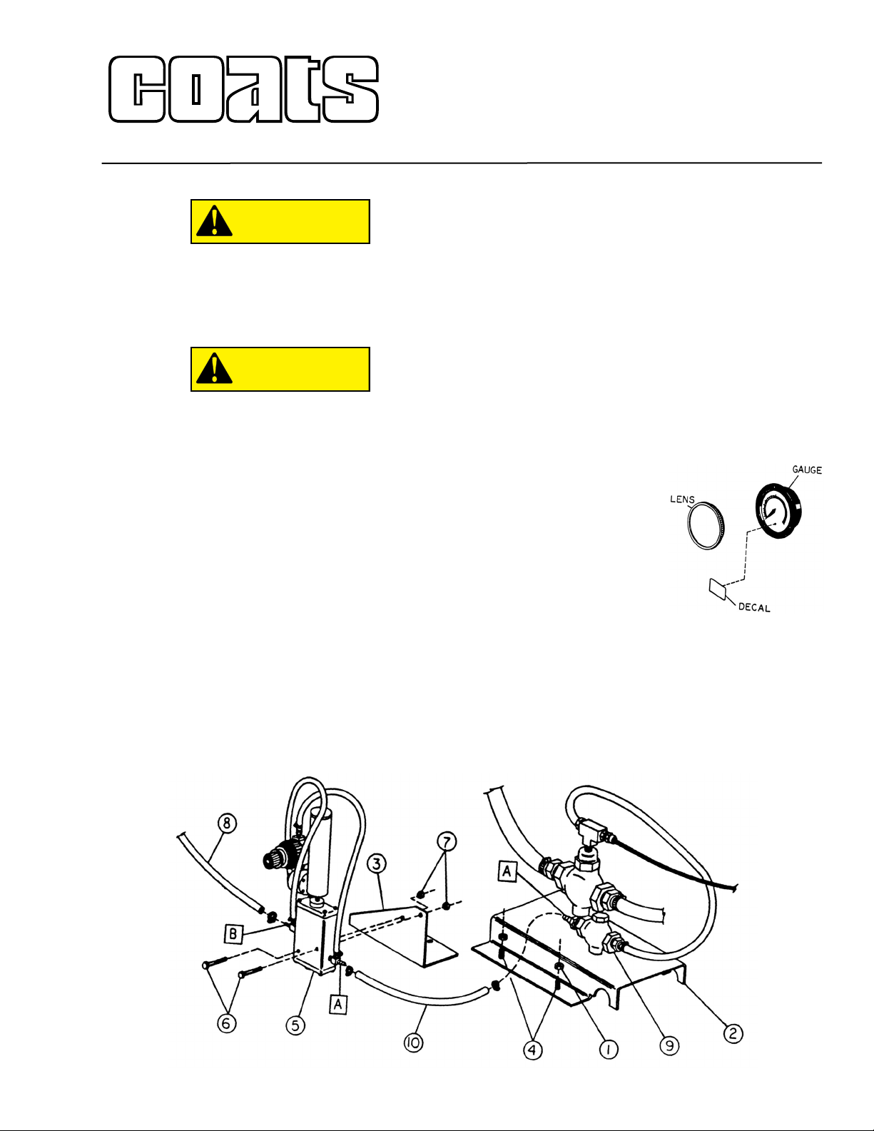
RC-15A and 15AA Pressure Limiter:
1. Remove the side panel.
2. Remove two nuts (ref 1), securing inflation valve
bracket (ref 2) to chassis.
3. Mount pressure limiter bracket (ref 3) to existing
bolts (ref 4) and securely tighten two nuts (ref 1).
4. Install pressure limiter (ref 5) to pressure limiter
bracket (ref 3) using two 1-3/4-inch long bolt (ref 6) and
two nuts (ref 7) provided in kit. Fasten securely.
5. Remove 1/4-inch hose (ref 8) from small valve (ref
9) and connect to port B on pressure limiter (ref 5).
6. Connect 1/4-inch hose 20-inches long (ref 10) sup-
plied in kit to port A on small valve (ref 9) and port A on
pressure limiter (ref 5). Securely tighten using 1/4-inch
hose clamps provided in kit.
7. Check all connections for proper installation and
tightness prior to reconnecting air supply.
8. Check unit for proper operation. Refer to the pres-
sure limiter maintenance section on page 4 of this
instruction.
9. Remove lens cover from
air gauge and install new
decal to gauge as shown in
diagram. Reinstall lens cover.
10. Replace side panel.
11. Review proper tech-
nique and operation with the
operators and supervisors.
CAUTION
CAUTION
Page 2
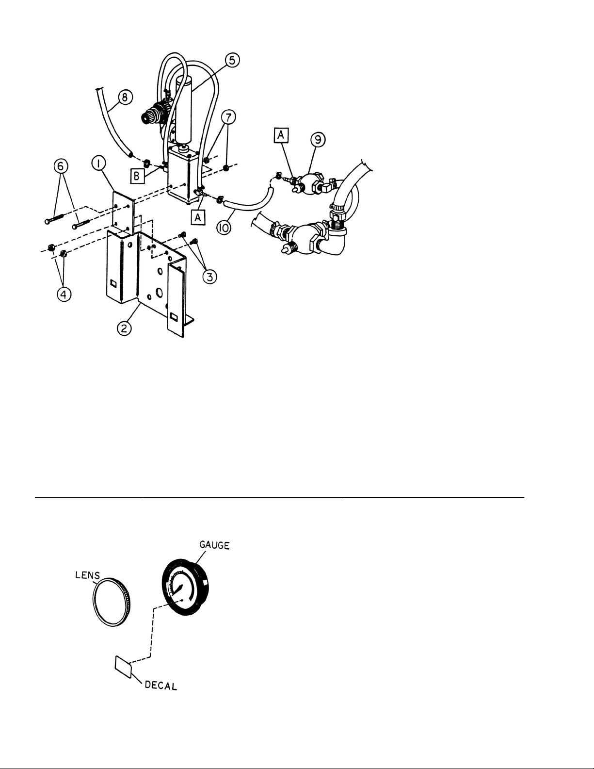
RC-20A and 20AA Pressure Limiter:
1. Remove the side panel.
2. Mount pressure limiter bracket (ref 1) to inflation
bracket (ref 2) using two 1/4-inch bolts 3/4-inch long (ref
3) and two 1/4-inch nuts (ref 4) provided in kit. Tighten
securely.
3. Install pressure limiter (ref 5) to pressure limiter
bracket (ref 1) using two 1/4-inch bolts, 1-3/4-inch long
(ref 6) and two nuts (ref 7) provided in kit. Fasten
securely.
4. Remove 1/4-inch hose (ref 8) from small valve (ref
9) and connect to port B on pressure limiter (ref 5).
5. Connect 1/4-inch hose 20-inches long (ref 10) sup-
plied in kit to port A on small valve (ref 9) and port A on
pressure limiter (ref 5). Securely tighten using 1/4-inch
hose clamps provided in kit.
6. Check all connections for proper instal-
lation and tightness prior to recon-
necting air supply.
7. Check unit for proper opera-
tion. Refer to the pressure limiter
maintenance section on page 4 of
this instruction.
8. Remove lens cover from air
gauge and install new decal to gauge
as shown in diagram. Reinstall lens
cover.
9. Replace side panel.
10. Review proper technique and operation with the
operators and supervisors.
8110585 01 2 of 4
40-40 Pressure Limiter:
1. Remove the operator’s side panel from the
machine.
2. Remove front side panel support from chassis by
removing two 3/8-inch self tapping screws. Install new
bracket (ref 1) in same location using the two 3/8-inch
self tapping screws just removed. Tighten securely.
3. Install pressure limiter (ref 2) to pressure limiter
bracket (ref 1) using two 1/4-20 x 1-1/2-inch long bolts
(ref 3) and two 1/4-20 lock nuts (ref 4) provided. Fasten
securely.
4. Disconnect quick coupler. Remove quick coupler
end from 1/4-inch hose (ref 7). Attach 1/4-inch hose (ref
7) to pressure limiter port A. Sercurely fasten all
clamps.
Page 3

5. Attach 37-inch long hose (ref
5) to pressure limiter port B.
Attach quick coupler end to
end of 37-inch long
hose. Securely fasten all clamps.
Reattach quick coupler.
6. Reinstall side
panel.
7. Check unit for proper
operation. Refer to the pressure limiter maintenance section on page 4 of this
instruction.
8. Remove lens cover from air gauge and install new
decal to gauge as shown in diagram. Reinstall lens
cover.
9. Review proper technique and operation with the
operators and supervisors.
Ref# Part No. Description
1 8103649 1/4" Hose x 12" L.G.
2 8109466 Valve
3 8109468 Pressure Repeater
4 8109471 1/8" Close Nipple
5 8109472 1/8" Inline Filter
6 8110325 1/4" NPT Male Run Tee
7 8110496 Volume Chamber
8 8111083 Regulator
9 8111255 Special Tee
10 8182035 Male Straight Fitting
11 8182038 1/4" OD Nylon Tube
12 85606362 14mm Spring Hose Clamp
13 8110497 Fitting - 90º Male Elbow
14 8143169 1/4"-20 Whiz Lock Nut
15 8120408 1/4"-20 x 1 3.4" H.H.C.S.
Pressure Limiter Kit Parts List
8110585 01 3 of 4
Page 4

Pressure Limiter Maintenance
Operating a tire changer with a defective,
improperly adjusted, or by-passed pressure
limiter could cause an operator to accidentally over pressurize a tire, resulting in a tire
explosion with severe injury or death to the
operator or bystanders.
Always be sure that the pressure limiter is
present and is operating properly.
Never inflate tire above manufacturer’s recommended pressure after bead is seated.
Pressure limiter is set at 60 PSI. Any required
inflation above 60 PSI should be performed
in an inflation chamber/safety cage or
securely mounted on the vehicle if an inflation chamber is not available. A tire explosion may cause personal injury or death to
operator or bystanders.
The pressure limiter helps prevent inflation of standard size or larger tires or tubes beyond 60 PSI to minimize risk of explosion. This device is for the safety of
the operator and bystanders. Proper operation of the
pressure limiter is essential to safe operation of the
machine.
Check operation of the pressure limiter as shown and
described below at least monthly and each time the
machine is serviced:
1. Remove tires and/or wheels from the machine.
2. Connect the inflation hose to an empty service
tank with a pressure gauge (gauge should read 0). Use
a service tank with a pressure rating of at least 100 PSI
and with a pressure relief valve set at the tank’s rated
pressure.
3. Depress inflation pedal to position 1 to start air-
flow through the hose and into the tank. Maintain a
steady pressure for constant flow.
4. Watch the rising pressure on the tank gauge and
the gauge on the machine. Machine gauge should
cycle between check and inflation pressures while tank
gauge climbs steadily. As tank pressure reaches 60
PSI, the pressure limiter should stop the airflow automatically. Both gauges should read 60 PSI ± 5 PSI.
5. Release inflation pedal. Check manual release
valve function by pressing the button and releasing
pressure from the tank until it reaches 15 PSI.
Disconnect inflation hose, and release air inside tank.
6. Replace pressure limiter if it fails to cycle properly
during inflation, if it fails to shut air supply off at 60 PSI,
or if it malfunctions in any other way. Do not operate
machine with a faulty pressure limiter.
DANGER
DANGER
8110585 02 06/09 4 of 4 © COPYRIGHT 1991 HENNESSY INDUSTRIES AND COATS ALL RIGHTS RESERVED PRINTED IN U.S.A.
Watch Pressure
on Both Gauges
Tire Changer
Inflation Hose
Connected to Tank
Air Service Tank
 Loading...