

Page 1
1601 J. P. Hennessy Drive, LaVergne, TN USA 37086-3565 615/641-7533 800/688-6359 Manual Part No.: 9112095 03
HENNESSY INDUSTRIES INC. Manufacturer of AMMCO
®
, COATS®and BADA®Automotive Service Equipment and Tools. Revision: 4/00
IBS 2000
Interactive Balancing System
®
Installation Instructions
Operating Instructions
Safety Instructions
Maintenance Instructions
READ these instructions before placing unit in
service KEEP these and other materials delivered
with the unit in a binder near the machine for
ease of reference by supervisors and operators.
Page 2

ii • COATS IBS 2000 Interactive Balancing System
Direct Drive
Page 3

COATS IBS 2000 Interactive Balancing System • iii
Table of Contents
Operator Protective Equipment . . . . . . . . .iv
Owner’s Responsibility . . . . . . . . . . . . . . . . .v
Definitions of Hazard Levels . . . . . . . . . . . . .v
Important Safety Instructions . . . . . . . . . . .vi
Before You Begin
Receiving . . . . . . . . . . . . . . . . . . . . . . . . . . . . . . . .1
Electrical Requirements . . . . . . . . . . . . . . . . . . . . .1
Specifications . . . . . . . . . . . . . . . . . . . . . . . . . . . .1
Features . . . . . . . . . . . . . . . . . . . . . . . . . . . . . . . . .2
Standard Accessories . . . . . . . . . . . . . . . . . . . . . .2
Optional Accessories . . . . . . . . . . . . . . . . . . . . . . .2
Installation and Setup
Floor and Space Requirements . . . . . . . . . . . . . . .2
Connect to Power . . . . . . . . . . . . . . . . . . . . . . . . .2
Operating Instructions
Interactive Control Panel . . . . . . . . . . . . . . . . . . . .3
The Planes . . . . . . . . . . . . . . . . . . . . . . . . . . . . . . .3
DWLS - Direct Weight Location System . . . . . . . .4
Balancing Modes . . . . . . . . . . . . . . . . . . . . . . . . . .4
Entering Wheel Data . . . . . . . . . . . . . . . . . . . . . . .5
Mounting Wheels
Back Cone Mounting . . . . . . . . . . . . . . . . . . . . . . .6
Front Cone Mounting . . . . . . . . . . . . . . . . . . . . . .6
Alternate Mounting . . . . . . . . . . . . . . . . . . . . . . . .7
Optional Combi-Adapter Mounting . . . . . . . . . . . .7
Selecting Balancing Options
Using the Menu . . . . . . . . . . . . . . . . . . . . . . . . . . .8
Setup . . . . . . . . . . . . . . . . . . . . . . . . . . . . . . . . . . .8
Reading the Displays . . . . . . . . . . . . . . . . . . .9
Balancing a Wheel
Procedure . . . . . . . . . . . . . . . . . . . . . . . . . . . . . . .9
Changing Wheel Information During Balancing . .10
Changing Balancing Modes and Weight Locations
During Balancing . . . . . . . . . . . . . . . . . . . . . . . . .10
Checking the Balance . . . . . . . . . . . . . . . . . . . . .10
After Balancing Vibration Problems . . . . . . . . . . .10
Match Mount
Description . . . . . . . . . . . . . . . . . . . . . . . . . . . . . .11
Is Match Mount Needed? . . . . . . . . . . . . . . . . . .11
Match Mount Instructions . . . . . . . . . . . . . . . . . .12
Maintenance . . . . . . . . . . . . . . . . . . . . . . . . .14
Total Accuracy Verification . . . . . . . . . . . . .14
Calibration and Diagnostics
Balancer Calibration . . . . . . . . . . . . . . . . . . . . . . .15
Plane Separation . . . . . . . . . . . . . . . . . . . . . . . . .16
A/D Arm Calibration . . . . . . . . . . . . . . . . . . . . . . .16
Diagnostics . . . . . . . . . . . . . . . . . . . . . . . . . . . . .17
Contents
Page 4
iv • COATS IBS 2000 Interactive Balancing System
Safety
Operator Protective
Equipment
Personal protective equipment helps make tire servicing safer. However, equipment does not take the
place of safe operating practices. Always wear durable
work clothing during tire service activity. Loose fitting
clothing should be avoided. Tight fitting leather gloves
are recommended to protect operator’s hands when
handling worn tires and wheels. Sturdy leather work
shoes with steel toes and oil resistant soles should be
used by tire service personnel to help prevent injury in
typical shop activities. Eye protection is essential during tire service activity. Safety glasses with side
shields, goggles, or face shields are acceptable. Back
belts provide support during lifting activities and are
also helpful in providing operator protection.
Consideration should also be given to the use of hearing protection if tire service activity is performed in an
enclosed area, or if noise levels are high.
Failure to follow danger, warning, and caution instructions may lead to serious personal injury or death to operator or
bystander or damage to property. Do not
operate this machine until you read and
understand all the dangers, warnings and
cautions in this manual. For additional
copies of either, or further information,
contact:
Hennessy Industries, Inc.
1601 J.P. Hennessy Drive
LaVergne, TN 37086-3565
(615) 641-7533 or (800) 688-6359
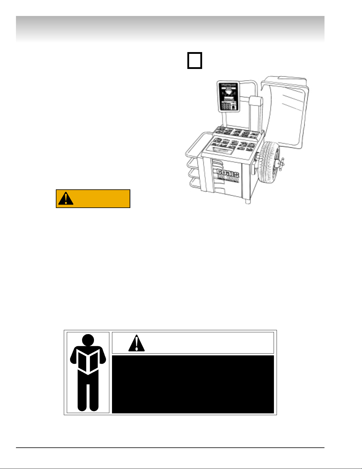
Do it Now
Make sure the instruction and warning decal is clean and clearly visible
to operator.
✓
NOTICE
Read entire manual before assembling,
installing, operating, or servicing this
equipment.
WARNING
Page 5
COATS IBS 2000 Interactive Balancing System • v
Owner’s Responsibility
To maintain machine and user safety, the responsibility of the owner is to read and follow these instructions:
• Follow all installation instructions.
• Make sure installation conforms to all applicable
Local, State, and Federal Codes, Rules, and
Regulations; such as State and Federal OSHA
Regulations and Electrical Codes.
• Carefully check the unit for correct initial function.
• Read and follow the safety instructions. Keep
them readily available for machine operators.
• Make certain all operators are properly trained,
know how to safely and correctly operate the unit,
and are properly supervised.
• Allow unit operation only with all parts in place
and operating safely.
• Carefully inspect the unit on a regular basis and
perform all maintenance as required.
• Service and maintain the unit only with authorized
or approved replacement parts.
• Keep all instructions permanently with the unit
and all decals/labels/notices on the unit clean and
visible.
• Do not override safety features.
Definitions of Hazard
Levels
Identify the hazard levels used in this manual with
the following definitions and signal words:
DANGER
Watch for this symbol:
It Means: Immediate hazards, which will result in
severe personal injury or death.
WARNING
Watch for this symbol:
It Means: Hazards or unsafe practices, which could
result in severe personal injury or death.
CAUTION
Watch for this symbol:
It Means: Hazards or unsafe practices, which may
result in minor personal injury or product or property
damage.
Watch for this symbol! It means BE ALERT! Your
safety, or the safety of others, is involved!
Safety
DANGER
WARNING
CAUTION
Page 6

vi • COATS IBS 2000 Interactive Balancing System
Safety
IMPORTANT SAFETY INSTRUCTIONS
SAVE THESE INSTRUCTIONS
READ ALL INSTRUCTIONS
1. Eye and face protection recommendations:
“Protective eye and face equipment is required to
be used where there is a reasonable probability of
injury that can be prevented by the use of such
equipment.” O.S.H.A. 1910.133(a) Protective goggles, safety glasses, or a face shield must be provided by the owner and worn by the operator of
the equipment. Care should be taken to see that
all eye and face safety precautions are followed by
the operator. ALWAYS WEAR SAFETY GLASSES.
Everyday glasses only have impact resistant
lenses, they are not safety glasses.
2. Do not disable hood safety interlock system, or in
any way shortcut safety controls and operations.
3. Be sure that wheels are mounted properly, the
hub nut engages the arbor for not less than four
(4) turns, and the hub nut is firmly tightened
before spinning the wheel.
4. Read and understand this manual before operating. Abuse and misuse will shorten the functional
life.
5. Be sure the balancer is properly connected to the
power supply and electrically grounded.
6. Do not operate equipment with a damaged cord
or if the equipment has been dropped or damaged
– until it has been examined by a qualified serviceman.
7. Do not let cord hang over edge of table, bench, or
counter or come in contact with hot manifolds or
moving fan blades.
8. If an extension cord is necessary, a cord with a
current rating equal to or more than that of the
equipment should be used. Cords rated for less
current than the equipment may overheat. Care
should be taken to arrange the cord so that it will
not be tripped over or pulled.
9. Keep guards and safety features in place and in
working order.
10. Wear proper clothing. Safety toe, non-slip
footwear and protective hair covering to contain
hair is recommended. Do not wear jewelry, loose
clothing, neckties, or gloves when operating the
balancer.
11. Keep work area clean and well lighted. Cluttered
and/or dark areas invite accidents.
12. Avoid dangerous environments. Do not use power
tools or electrical equipment in damp or wet locations, or expose them to rain.
13. Avoid unintentional starting. Be sure the balancer
is turned off before servicing.
14. Disconnect the balancer before servicing.
15. Use only manufacturer’s recommended accessories. Improper accessories may result in personal injury or property damage.
16. Repair or replace any part that is damaged or worn
and that may cause unsafe balancer operation. Do
not operate damaged equipment until it has been
examined by a qualified service technician.
17. Never overload or stand on the balancer.
18. Do not allow untrained persons to operate
machinery.
19. To reduce the risk of fire, do not operate equipment in the vicinity of open containers or flammable liquids (gasoline).
20. Adequate ventilation should be provided when
working on operating internal combustion
engines.
21. Keep hair, loose clothing, fingers, and all parts of
body away from moving parts.
22. Use equipment only as described in this manual.
23. Use only manufacturer’s recommended attachments.
Page 7
Before You Begin
Receiving
The shipment should be thoroughly inspected as soon as it is
received. The signed bill of lading is acknowledgement, by the
carrier, of receipt in good condition of the shipment covered by
our invoice.
If any of the goods called for on this bill of lading are shorted
or damaged, do not accept them until the carrier makes a notation of the shorted or damaged goods on the freight bill. Do this
for your own protection.
NOTIFY THE CARRIER AT ONCE if any hidden loss or damage
is discovered after receipt and request him to make an inspection. If the carrier will not do so, prepare an affidavit to the effect
that you have so notified the carrier (on a certain date) and that
he has failed to comply with your request.
IT IS DIFFICULT TO COLLECT FOR LOSS OR DAMAGE AFTER
YOU HAVE GIVEN THE CARRIER A CLEAR RECEIPT.
File your claim with the carrier promptly. Support your claim
with copies of the bill of lading, freight bill, invoice, and photographs, if possible.
Although COATS responsibility ceases upon delivery of the
shipment to the carrier, we will gladly assist in tracing lost shipments. Our willingness to assist in every possible manner does
not make COATS responsible for collection of claims, or replacement of lost or damaged materials.
Electrical Requirements
The IBS 2000 requires a 220 VAC, 60Hz, three-phase power
supply with 20 amp fuse or circuit breaker, or a 220 VAC, 60HZ,
single-phase power supply with 20 amp fuse or circuit breaker.
The three-phase balancer is equipped with an approved cord
and a 4-prong grounding plug to fit a Hubbell 2420 or Bryant
71520 grounding receptacle (not included). See figure 1.
The single-phase balancer is equipped with an approved cord
and a 3-prong grounding plug to fit a Hubble 2323 or Bryant
grounding receptacle (not included). See figure 2.
A qualified electrician should install the receptacles in accordance with state and local codes.
Specifications
• Cycle time . . . . . . . . . . . . . . . . . . . . .4 to 5 seconds (avg.)
• Outside Tire Diameter . . . . . . . . . . . . . . . . .44 inches max.
• Wheel Diameter Range . . . . . . . . . . . . . . .8 to 29.9 inches
• Wheel Width Range . . . . . . . . . . . . . . . . . . .2 to 19 inches
• Balancing Increments . . . . . . . . . . . . . .0.25 or 0.01 ounce
• Resolution (Round Off Mode) . . . . . . . . . .0.01 ounce, 1.4°
• Motor - Modified torque with 900 RPM/1.5 HP rating, forced
air cooling, large housing for heat dissipation, and heavy
duty insulation for high temperature applications.
• Shipping Weight . . . . . . . . . . . . . . . . . . . . . . . .625 pounds
Direct Drive
COATS IBS 2000 Interactive Balancing System • 1
Figure 1 - Three-Phase Wiring Diagram
Three-Phase
Ground
Hot
195-230 V
Between
Hot Wires
Hot
Hot
Figure 2 - Single-Phase Wiring Diagram
Single-Phase
A – Red
B – Black
Green/
Ground
Page 8
2 • COATS IBS 2000 Interactive Balancing System
Direct Drive
Features
• Exclusive Direct Drive System (no belts or pulleys)
• Single-Spin Balancing
• Hood Safety Interlock System
• Extended Mounting Flange for Deeper Wheels
• Dynamic, Static, RV, Match Mount, and Alloy
Balancing Modes
• Interactive Control Panel
• Large, Bright Digital Displays
• Easy-to-Read Weight Position Indicators
• Large Keypad for Data Entry
• Control Pod Adjusts for Optimum Visibility
• Electronics Isolated from Motor Heat
• Automatic Memory and Program Check
• Interactive Display Menu
• Dual Operator Modes (Operator A/B)
• Stop-On-Top for Easier Weight Location
• Automatic Offset and Diameter Data Entry
• Self-Calibrating
• Weight Storage Bins and Accessory Pegs
• No-Bolt-Down Installation
Standard Accessories
• Graduated Cone Assortment (hardened, 3 piece)
• Light Truck Cone
• Hub Nut
• No-Mar Ring
• Rim Width Caliber
• Wheel Weight Pliers
Optional Accessories
• Combi-Adapter for Bolt Hole Mounting
• Extra Large Truck Cone Kit
• 3, 4, and 5 Lug Flange Plate Adapters
• Escort/Lynx Adapter
• Speed Lock Kit
• Side and Rear Storage Trays
• Viper Wheel Kit
• Large Truck Cone and Cup Adapter Kit
• Tacoma Cone
Installation and Setup
A factory trained COATS®Service Technician must
perform the install, setup, and initial test procedures
on your IBS 2000 balancer. Do not attempt to install
and setup the unit yourself. Accurate and reliable operation of your unit depends on proper installation.
Please contact COATS®directly at 1-800-688-9240 for
the Certified Service Partner nearest you.
Do not use the control pod, control pod
arm, faceplate, hood or shaft to lift the balancer.
Floor and Space Requirements
The balancer must be located on a flat floor of solid
construction, preferably concrete. The balancer must
sit solidly on its three feet. If the balancer is not level,
does not sit solidly on its three feet, or is placed on an
unstable floor, the balancer will not function properly
and will produce inaccurate balance readings.
Do not operate the balancer when it is still bolted
down or while it is on the pallet.
Select a location for the balancer that provides a
level, solid floor, and adequate clearance around and
above the balancer. Make sure the location selected
has enough room above and behind the unit so the
hood can be raised completely. The location must also
provide working room for mounting and removing
wheels.
Connect to Power
Your factory trained COATS®Service Technician
should do the final check to verify the power installation before connecting the balancer to a power supply.
Failure due to improper power connection will void the
warranty.
CAUTION
Page 9

Operating Instructions
Interactive Control Panel
Weight Displays
Wheel Position Indicators
Location Indicator LEDs/Selection Buttons
Interactive Display Screen
Mode Display
Keypad
Manual Start Button
The Planes
The IBS 2000 is a 2-plane, microprocessor-based
computer balancer. Any imbalance in a wheel, either
static or dynamic, is resolved into correction planes
where corrective weights can be applied. Refer to
Figure 3 for the preset plane locations. The five weight
location indicators on the control panel correspond to
the 5 planes.
COATS IBS 2000 Interactive Balancing System • 3
Direct Drive
Figure 3 - The Five Planes
Page 10

4 • COATS IBS 2000 Interactive Balancing System
Direct Drive
DWLS - Direct Weight Location System
The IBS 2000 allows the operator to use preset
weight location positions or measured location positions. The measured location positions increase accuracy on alloy wheels and when using hidden weights.
Select between these by using the MODE button.
When using the PRESET measurements, the operator enters the standard A, W, and D measurements.
After these measurements are entered, the computer
based upon wheel profile data stored in the computer
makes corrective weight locations. These calculations
allow the computer to display weight information for
the weight locations selected by the operator. Once
the A, W, and D measurements are entered, the operator may select any of the five weight locations and
the computer will display the calculated weight
amount to be attached at that location.
When using the MEASURED MODE in conjunction
with standard clip-on weights, for BOTH planes, the
operator measures and enters the A, W, and D in the
traditional method by touching the inner rim flange
with the A&D arm and reading the width with the
wheel calipers.
When using the MEASURED MODE in conjunction
with a single clip-on weight and a hidden tape-aweight™ or two hidden tape-a-weights™, the operator measures the specific weight location in which he
wishes to place a weight. The operator selects locations for the weight from plane 1, 2, or 3 by pressing
the button on the display panel adjacent to the plane
of choice. (See figure 3) The operator then uses the
A&D arm to measure the selected location at the
flange or inside the rim.
Note: Always measure from the inner most plane
first, then move outward, away from the balancer. For
example, if the operator selects plane 3 and plane 1
the operator must measure the plane 1 location first,
wait for a confirmation BEEP, and then measure plane
3 again waiting for a confirmation BEEP. These measurements are displayed on the LCD screen as AIN,
DIN, and AOUT, DOUT.
When using tape-a-weights™ and measuring inside
the rim, we recommend rotating the A&D arm down
so that the tip of the A&D arm is pointing towards the
ground and measuring the lower part of the rim. In
this position, you can see where you are touching for
the measurement. By seeing the position it will be
easier when placing the tape-a-weight after the spin
cycle. Also, traditionally when placing the weight you
would rotate the wheel until the center light flashes,
you are at what we call "Top Dead Center", or at the
location you would attach the weight. There is an alternative, if you marked the Top Dead Center on the rim
and rotate the wheel 180 degrees until you see the
two outermost lights flash the mark is at we call
"Bottom Dead Center". When placing a tape-a-weight
at the bottom of the rim you have a better visual sighting and more accurate placement.
Remember to return the A&D Arm back to it's home
position after use.
Tip! Keep the arm moving until you are ready to take
a reading, the arm will automatically take a reading if
it is not moved. Place the tip or disk at the weight location and hold it firmly in place for two seconds and listen for a confirmation BEEP, move the arm
immediately to the next location and wait again for
two seconds and listen for another confirmation BEEP.
Note: It is good practice when dynamic balancing for
the distance (the W dimension) between the two
weight locations to be as wide apart as physically possible. This will improve the balance of the wheel and
productivity.
Recommendation: Using the PRESET MODE will
provide easy balancing and yield accurate results
when used for the standard clip-on weights. However,
when using the PRESET MODE for tape-a-weights™
you will probably have to make repeated spins to balance the wheel. We encourage you to learn and
become proficient with the use of the MEASURED
MODE. This mode works equally well when measuring for the standard clip-on weights and works particularly well when using a combination of only one-clip
on weight and one tape-a-weight™ or when using
tape-a-weights for both planes. Using the "MEASURED" A and D weight locations, you will balance
wheels with more ease and with increased accuracy.
This will provide your best solution for single spin balancing in all modes and greater customer satisfaction.
Balancing Modes
Select between DYNAMIC and STATIC balancing
modes by pressing the button between their respective LEDs on the control panel.
The DYNAMIC balancing mode calculates separate
corrective weight requirements for the inner and outer
planes of the wheel. The default locations are planes
1 and 5. The specific weight amount and location for
each plane is calculated in a single spin.
The default STATIC balancing mode calculates a single corrective weight requirement for placement at a
point as close to the center of the wheel as possible
(plane 3). The IBS 2000 allows the operator to select
any of the other locations for this weight placement
simply by pressing the corresponding location button
on the display screen. The operator may also opt to
split this single weight between two planes (1 and 5)
Page 11

COATS IBS 2000 Interactive Balancing System • 5
by pressing location button 5 followed by location button 1. Both location LEDs will light, and the static correction weight amount will be split between the two
weight displays. The weights will attach to the same
position on both the inner and outer rim flanges
(directly opposite each other).
RV MODE is used to balance larger wheels that do
not require balancing of increments less than 0.5ounces. This mode is selected by pressing MENU on
the display screen, then selecting SETUP, and choosing RV MODE from the available options in the SETUP
menu.
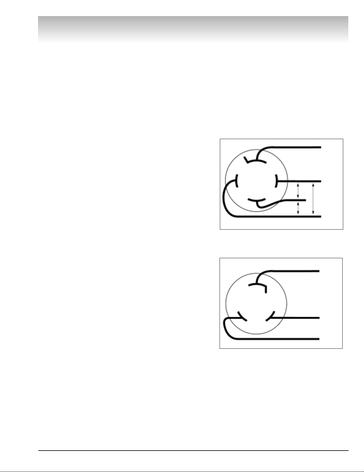
Entering Wheel Data
Before any wheel can be balanced, the computer
must know its size and position on the arbor. These
measurements are:
A (Wheel Offset) -The distance between the side of
the balancer and the inner edge of the wheel.
D (Wheel Diameter) - This is the diameter of the
wheel at the weight location.
W (Wheel Width) - This is the width of the wheel at
the rim flanges. This is measured with the calipers.
Figure 4 - A/D Arm Measurement Points
The A and D measurements can be entered into the
balancer automatically using the A/D arm. Simply pull
the A/D arm out from the side of the machine and
rotate it until it contacts the desired location on the
wheel. Hold the arm in place until the BEEP is heard
and the measurement data is displayed on the screen.
When measuring to the rim flange, touch the tip of the
A/D arm pointer to the rim flange. When entering
measurements for plane 2 or 3 (MEASURED MODE),
touch the disk around the A/D arm pointer to the location.
Note: The computer reads the automatic diameter
entry as three decimal places (0.000) and rounds the
measurement to two decimal places (0.00). It is not
necessary to convert metric measurements to inches.
Also remember that wheel diameter may vary
depending on rim flange configuration (i.e.: a 14-inch
wheel may display a measurement of 13.6 to 14.3).
For manual entry, enter the inch unit to a single decimal place (0.0). The diameter is included on the tire
sidewall (i.e.; 14, 16, 16.5, etc.).
The A and D measurements may also be entered
manually simply by pressing the corresponding button
on the display screen and entering the number using
the keypad.
To enter the W measurement, touch the button on
the display screen that corresponds to the W measurement and enter the number using the keypad. Take
the width measurement with the calipers. Place the
calipers over the wheel and touch the tips of the
caliper arms to the rim flanges. Read the width on the
scale, see figure 5.
Tip! Watch the display screen. It will show all the
measurements entered or being taken, and any others that are required. If you attempt to balance a
wheel with a measurement missing, the screen will
notify you and prompt you to enter the missing data.
Figure 5 - Measuring Wheel Width with the Calipers
Direct Drive
Use Tip to Measure to
Rim Flange
Use Disk to Measure to
Horizontal Surfaces
Tip
Disk
Page 12

Mounting Wheels
Select the most appropriate mounting method for the wheel
you are balancing. Using the proper method ensures secure
mounting and safe balancer operation, and prevents damage to
the wheel.
On most wheels, the inner side of the wheel hub usually has
the most uniform surface for wheel balancing. Always center
the wheel by the most uniformly shaped side of the hub to
achieve the most accurate balance.
Regardless of mounting type, always make sure that the
wheel is forced firmly against the arbor faceplate and that the
hub nut engages the threaded arbor for at least four complete
turns. To assist in centering the wheel properly, rotate the wheel
on the arbor while tightening the hub nut.
Back Cone Mounting
Most original equipment and steel wheels can be mounted
properly using this method. The wheel is centered on a cone
from the inner side of the hub.
1. Place the cone spring on the arbor with the large end
towards the balancer.
2. Select the cone that best fits the center hole in the wheel.
Slide the cone onto the arbor with the large end towards the
spring.
3. Lift the wheel onto the arbor and center it on the cone.
4. Attach the pressure cup to the hub nut and spin the assem-
bly onto the arbor. Tighten securely.
Front Cone Mounting
A wheel should be centered by the outer side of the hub only
when the inner surface will not provide an accurate surface to
center on.
1. Select the cone that best fits the center hole in the wheel.
2. Lift the wheel onto the arbor and slide it back against the
arbor faceplate.
3. Slide the cone onto the arbor and into the center of the
wheel. You will need to lift the tire to seat the cone in the center hole.
4. Spin the hub nut (without pressure cup) onto the arbor.
Tighten it securely against the cone.
Direct Drive
6 • COATS IBS 2000 Interactive Balancing System
Figure 6 - Back Cone Mounting
Figure 7 - Front Cone Mounting
Rim
Spring
Cone
Hub Nut
Pressure Cup
Rim
Hub Nut
Cone
Page 13

Alternate Mounting
If the wheel has a protruding outer hub which will not permit
the use of the pressure cup, or the cup will not permit the hub
nut to engage at least four turns of the arbor, this alternate
method should be used.
1. Place the cone spring on the arbor with the large end
towards the balancer.
2. Select the cone that best fits the center hole in the wheel.
Slide the cone onto the arbor with the large end towards the
spring.
3. Lift the wheel onto the arbor and center it on the cone.
4. Use the small nylon spacer (no-mar ring) or a centering
cone to press against the outer wheel hub.
5. Spin the hub nut (without the pressure cup) onto the arbor.
Tighten securely.
Optional Combi-Adapter Mounting
Use this method for wheels with a center hole that is out of
round, or center holes that do not fit the mounting cones. This
adapter allows the mounting of 3, 4, 5, 6, 8, or 10 lug wheels by
installing 3, 4, or 5 swivel plates on the adapter plate.
1. Assemble the adapter according to the instructions pro-
vided.
2. Attach the adapter to the wheel. The lug nuts must properly
seat in the lug holes and engage at least four full threads for a
secure mounting. Use the wrench provided with the adapter,
and never use air tools or impact wrenches.
3. Lift the wheel onto the balancer and align the adapter base
plate studs with the holes in the arbor faceplate. Secure the
adapter/wheel to the faceplate using the thumb nuts. To properly center the wheel, tighten the thumb nuts in an alternating
pattern while rotating the wheel.
Direct Drive
COATS IBS 2000 Interactive Balancing System • 7
Figure 8 - Alternate Mounting
Cone
Spring
No Mar Ring
Hub Nut
Figure 9 - Optional Combi-Adapter Mounting
Swivel Plate
Swivel Plate Bolt
Washer
(optional)
Faceplate
Nut
Number
Gear
Center
Bushing
Alignment
Mark
Combi Plate
Alignment
Page 14

8 • COATS IBS 2000 Interactive Balancing System
Direct Drive
Selecting Balancing
Options
Using the Menu
Use the menu on the interactive display to access
setup screens, match mount procedures, calibration,
and diagnostics. Open the menu by pressing the
MENU button on the display. The five buttons below
the display will be labeled with their function for each
screen you access.
These buttons typically are (from left to right):
ENTER, PREVIOUS, EXIT, up arrow, and down arrow.
Pressing ENTER toggles your current selection on or
off (or selects the option), PREVIOUS returns you to
the previous screen, and EXIT returns you to the top
of the menu. Use the scroll up and scroll down arrows
to scroll through options and selections. Up and/or
down arrows will be displayed at the top or bottom of
the screen if there is more information above or below
what's shown.
Match Mount - (see pg.11)
Calibration
• Calibrate Balancer - (see pg.14)
• Calibrate Arm - (see pg.15)
Set Up
Round Off -The default weight measurement on the
IBS 2000 is 0.25-ounce. The balancer can be set to a
non-Round Off mode that displays weights in 0.01ounce increments. Select SETUP from the menu,
select ROUND OFF from the list, and press ENTER to
turn this option on or off. Status of this option is
shown in the top of the display as well.
Ounces or Grams - Set the balancer to measure and
display weight amounts in grams. Select SETUP from
the menu, select OUNCE or GRAM from the list, and
use ENTER to select the weight type. Status of this
option is shown in the top of the display as well.
Hood Start - Sets the balancer to start spinning as
soon as the hood is fully lowered. Select SETUP from
the menu, select HOOD START from the list, and use
ENTER to turn this option on or off. Status of this
option is shown in the top of the display as well.
RV Mode - For wheels that do not require balancing
in increments of less than 0.5-ounce. Calculates balancing weights in 0.5 increments only. Select SETUP
from the menu, select RV MODE from the list, and
use ENTER to turn this option on or off.
Stop-on-Top - The IBS 2000 will automatically brake
the wheel to a stop at the end of a spin cycle. The balancer will brake once to slow the wheel and a second
time to stop the wheel with the outer weight position
at or near the top. If no weight is required on the outer
plane, it will brake the wheel to stop based on the
inner weight position. Select SETUP from the menu,
select STOP ON TOP from the list, and use ENTER to
turn this option on or off.
Total Accuracy Verification (TAV) - (see pg.14)
LED Intensity -The LED brightness may be adjusted
to make them easier to read in all lighting environments, bright as well as dark, and those in between.
The last item on the MENU list is LED INTENSITY.
Select this item from the menu and follow the instructions on the display to brighten or dim the LEDs.
Diagnostics - (see pg.17)
Operator A/B - Two operators utilize the balancer
without clearing or changing each others data. This is
handy when one operator is running the Match Mount
procedure and another operator needs the balancer.
For example, if operator A is at a point in the Match
Mount procedure where the wheel is removed from
the balancer, operator B can access the machine by
switching to the other operator memory. When B's
balance is complete, he can toggle the machine back
to A's memory. All of operators A's data is still present, and the Match Mount procedure can be continued without having to start over. Press the
OPERATOR key to toggle between the two operator
memories.
Page 15

COATS IBS 2000 Interactive Balancing System • 9
Reading the Displays
Weight Displays - The two weight displays (one for
the inner plane, and one for the outer plane) are positioned with a wheel cross section diagram. After spinning the wheel, the balancer will calculate the weight
needed and display it in these displays. The display to
the left of the diagram will show the weight to be
applied to the inner plane of the wheel and the display
to the right will show the weight for the outer plane.
Weight Position LEDs - Each weight display
includes weight position LEDs. Located between the
weight display and the diagram, these LEDs indicate
the proper location for weight application. After a spin,
rotate the wheel until the center position indicator
LEDs flash. This indicates that the position specified
by the balancer for weight application is at top-deadcenter.
Balancing a Wheel
Procedure
The following steps walk through the balancing procedure. Do not proceed with these instructions until
you have read and understand the previous sections
of this guide (mounting, balance modes, and reading
the displays).
1. Turn the balancer on. The power switch is on the
right side of the tower at the side of the unit.
Note: When turned on, the balancer will activate the
same options that were selected when it was last
turned off (hood start, ounce/gram, etc.).
2. Mount the wheel to be balanced. Use the proper
mounting method as described on pages 6 and 7.
Always remove any weights attached to the wheel.
3. Enter the wheel measurements and select bal-
ancing mode (page 4 and 5).
4. Set options (hood start, ounce/gram, operator
A/B).
5. Lower the hood and press START. The wheel will
spin and then brake to a stop.
Note: Spin will start automatically when the hood is
lowered if the hood start option is turned on.
6. Raise the hood.
7. Rotate the wheel until the outer position LEDs
flash.
8. Attach the weight specified in the proper location
at top-dead-center. Refer to the diagrams on the control panel for weight locations.
9. Rotate the wheel until the inner position LEDs
flash.
10. Attach the weight specified in the proper loca-
tion at top-dead-center. Refer to the diagrams on the
control panel for weight locations.
11. Lower the hood and press START to respin the
wheel. The wheel will brake to a stop. The weight displays should now read 0.00. If not, refer to page 10,
Checking the Balance for assistance.
Remember: The more accurate you are in selecting
and positioning the weight, the more often you will
balance wheels with a single spin.
Direct Drive
Page 16

10 • COATS IBS 2000 Interactive Balancing System
Direct Drive
Changing Wheel Information During
Balancing
The information entered into the balancer for A, W,
and D can be changed at anytime during the balancing
procedure. Follow the instructions provided earlier for
entering the measurements manually. The balancer
will recalculate weights and positions based on the
new measurements.
Changing Balancing Modes and Weight
Locations During Balancing
The balancing mode can be changed at anytime and
the balancer will recalculate weight and position
based on the new selection. In PRESET MODE, the
computer will calculate the new weight amount and
location when the operator selects a different weight
location. In the MEASURED MODE, selecting a new
weight location will require new A and D data. Once
entered, the computer will calculate weight amount
and location.
Note: This does not apply when switching to and
from Match Mount. The Match Mount procedure
requires additional steps. Refer to the Match Mount
section of this manual.
Checking the Balance
After applying the weights indicated by the balancer,
respin the wheel. The displays should read 0.00.
If the balancer indicates an additional weight should
be applied in the same location as the first weight, the
first weight is too small. Correct the first weight and
respin.
If the balancer indicates an additional weight should
be applied directly opposite the first weight, the first
weight is too big. Correct the first weight and respin.
If the balancer indicates an additional weight should
be applied at an angle to the first weight, the first
weight was not applied in the correct position. Move
the first weight towards the position indicated for the
second weight or add the second weight as indicated.
After Balance Vibration Problems
If vibration is still present after balancing the wheels
and driving the vehicle on smooth pavement, remove
the wheels and recheck the balance. If a wheel is out
of balance the cause may be:
1. A weight has come off the wheel. Remove the
other weights from the wheel and rebalance.
2. Tire slippage on the wheel. Remove and remount
the tire using proper tire lubricant and inflate to 40
PSI. Do not overinflate. Rebalance the wheel and
reduce air pressure to recommended PSI.
3. Stones or other foreign objects caught in the tire
tread. Remove the objects and repair tire as necessary. Check and rebalance if needed.
If the balancer still indicates the wheels are balanced
to within 0.25-ounces on both inner and outer displays, the problem is not in the balance of the wheels.
Check the following possible sources of vibration:
1. Tire pressure. Bring all tires up to the recom-
mended PSI.
2. Radial or lateral runout in the tire or wheel.
Replace the damaged part.
3. Foreign material inside the tire. Remove the tire
from the wheel, remove the material, and remount.
Remove wheel weights and rebalance the wheel.
4. Imbalanced wheel covers or trim rings. Remove
the wheel covers or trim rings and test drive. If the
vibration is gone, remove the arbor and use the
optional Combi Adapter to mount the wheel to the
balancer. Balance the wheel with the wheel cover or
trim ring attached to the wheel.
5. Incorrectly mounted wheel. Remount correctly.
6. Damaged wheel bolt holes. Replace wheel.
7. Worn universal joints. Replace as required.
8. Drive shaft imbalanced or damaged. Balance,
repair, or replace.
9. Imbalanced brake rotor(s) or drum(s).
10. Suspension out of alignment. Align the vehicle
and replace any damaged or worn parts.
Page 17

COATS IBS 2000 Interactive Balancing System • 11
Match Mount
Description
The Match Mount program assists the user in determining the best possible mating of the tire and wheel,
thereby reducing the amount of additional weight
required for balancing. This mating of tire and wheel
normally allows the least amount of total runout of the
assembly, resulting in better balancing, better ride
conditions, and more satisfied customers. Use Match
Mount when:
• Excessive radial runout is noticed in the tire and
wheel assembly during balancing.
• The customer complains of ride problems.
• The balancer calls for weights in excess of 2ounces on either plane on passenger car tires in the
DYNAMIC MODE.
The Match Mount procedure involves loosening tire beads and the inflation of a tire.
Training is necessary in tire changer operation and the dangers involved during bead
seating and tire inflation before attempting
this stage of the Match Mount procedure.
Read the operators manual supplied with
the tire changer and consult a supervisor.
The 2000 balancer will be idle while the tire is being
rotated on the wheel. During these times, the balancer can be used by another operator without terminating the Match Mount procedure. The second
operator selects the other operator memory, performs
a balance, and then returns the balancer to the previous memory. The original operator can now continue
the Match Mount procedure.
As with any balancing procedure, remove any
weights attached to the wheel and inspect the tire and
wheel before beginning.
Is Match Mount needed?
1. Mount the wheel to the balancer.
2. Select the appropriate operator memory as
required (A or B). Make a note of the memory being
used in the event the memory is changed during the
Match Mount procedure.
3. Enter the A, W, and D measurements and select
the mode that will be used in the final balancing.
4. Lower the hood and press START.
5. Wait for the wheel to stop spinning and for the
displays to show weight readings.
• If the balancer indicates that 2-ounces or more will
be required on either plane (in DYNAMIC MODE),
advise the customer/ supervisor to continue with the
Match Mount procedure listed under Match Mount
Instructions. DO NOT attach weights at this point.
Leave the wheel mounted to the balancer.
• If the balancer indicates less than 2-ounces of
imbalance, the Match Mount procedure will not
improve the balance. Continue to balance the wheel
according to the mode selected.
Direct Drive
WARNING
Page 18

Match Mount Instructions
1. Select Match Mount from the LCD menu.
• Hood start is turned off automatically
• Non-round off is turned on automatically
• MM will now be displayed in the upper left corner of the LCD
screen.
• Enter wheel parameters
2. Lower the hood and press START.
• MATCH MOUNT 1 will now be displayed in the upper left
corner of the LCD screen.
3. Raise the hood and rotate the wheel until the valve stem is
at top-dead-center.
4. Press 1 on the touch panel.
• MATCH MOUNT 2 will now be displayed in the upper left
corner of the LCD screen.
5. Press the MORE softkey to read the second page of
instructions on the LCD screen.
6. Remove the wheel from the balancer. Completely deflate
the tire by removing the valve core. After all the air pressure is
exhausted, follow the tire changer manufacturer's instruction for
loosening the tire beads.
A second operator can use the 2000 balancer while the Match
Mount operator performs steps 6, 7, and 8. All data for the
Match Mount procedure will be kept in the Match Mount operator's memory (A or B).
7. Lubricate both tire beads and wheel to aid in rotating the
tire and bead sealing and seating. Always use the tire manufacturers approved rubber lubricant.
8. Rotate the tire 180° on the wheel.
9. Replace the valve core and inflate the tire. Follow the tire
changer manufacturers instructions for inflation.
10. Remount the wheel on the balancer.
Remember: If another operator memory (A or B) has been
selected, reselect the memory being used for the Match Mount
procedure. The balancer will return to the point in the procedure
where the other memory was selected.
11. Press the 2 on the touch panel
• MATCH MOUNT 3 will be displayed in the upper left corner
of the LCD screen.
12. Lower the hood and press START.
13. Wait for the wheel to stop. Raise the hood and rotate the
wheel until the valve stem is at top dead center.
Direct Drive
12 • COATS IBS 2000 Interactive Balancing System
Figure 10 - Rotate the wheel
Figure 11 - Rotate Tire on Wheel
Tire/wheel
assembly rotated
until valve stem
is at top-deadcenter.
Tire rotated 180
degrees on the
wheel.
Figure 12 - Rotate the Wheel
Tire/wheel
assembly rotated
until valve stem
is at top-deadcenter
Page 19

14. Press 4 on the touch panel.
• MATCH MOUNT 4 will be displayed in the upper left corner
of the LCD screen.
15. Rotate the wheel until the weight position LEDs flash.
While the LEDs are flashing, mark the tire at top dead center
and press CONTINUE.
16. Press the MORE softkey to read the second page of
instructions on the LCD screen.
The weight breakdown will now be displayed on the LCD
screen. The weight imbalance due to the wheel (rim) will be displayed above the weight imbalance for the tire. The percent of
the total weight is also given to aid in determining, which has
the greater effect on the imbalance, the tire and/or wheel.
Use these weights to determine the suitability of the rim or
tire. High imbalance may indicate a rim that is out of round or
misformed, or a tire with a bubble or other problem. If the imbalance is excessive, it may be prudent to replace the rim, the tire,
or both. If either is replaced, do not continue with this procedure. Balance the new tire and rim and evaluate the readings for
Match Mount suitability.
17. Remove the wheel from the balancer. Completely deflate
the tire by removing the valve core. After all the air pressure is
exhausted, follow the tire changer manufacturer instructions for
loosening the tire beads.
A second operator can use the 2000 balancer while the Match
Mount operator performs steps 18, 19, and 20. All data for the
Match Mount procedure will be kept in the Match Mount operator's memory (A or B).
18. Lubricate both tire beads and wheel to aid in rotating the
tire and bead sealing and seating. Always use the tire manufacturer's approved rubber lubricant.
19. Rotate the tire until the mark is aligned with the valve
stem.
20. Replace the valve core and inflate the tire. Follow the tire
changer manufacturer instructions for inflation.
Remember: If another operator memory (A or B) has been
selected, reselect the memory being used for the Match Mount
procedure. The balancer will return to the point in the procedure
where the other memory was selected.
21. Remount the wheel on the balancer.
22. Press CONTINUE.
23. The balancer will return to standard balancing mode.
Direct Drive
COATS IBS 2000 Interactive Balancing System • 13
Figure 13 - Rotate the wheel
Tire/wheel
assembly rotated
until weight position lights
flashed. Tire
marked at topdead-center.
Figure 14 - Rotate Tire on Wheel
Figure 15 - Match Mount Completed
Tire rotated so
mark is aligned
with valve stem.
Wheel ready for
balancing
Page 20

14 • COATS IBS 2000 Interactive Balancing System
Direct Drive
Maintenance
The balancer requires only minor maintenance to
keep the unit operating properly.
1. Keep the display clean and clear. Use a vaporizing
cleaner only. Do not use cleaners or solvents which
leave oily or filmy residues behind.
2. Keep the adapters, cones, faceplate, threaded
arbor, pressure cup, and hub nut clean. Grease and
dirt buildup will cause premature wear and inaccurate
balancing. Clean these items at least once a day with
a vaporizing solvent.
3. Clean the weight tray, accessory posts, pegs, and
storage shelves with a vaporizing solvent. Weights
stored in a dirty tray will pick up grease and dirt which
may alter their weight or keep them from securely
attaching to the wheel.
Do not hose down or bucket wash the balancer. Extensive damage to the balancer
will result. Sensitive electronic components, wiring harnesses, and other devices
housed in the balancer are not intended to
be exposed to water.
Exposing the balancer to water, either by
hose pipe or bucket, or by exposure to rain
or snow, may cause risk of shock or electrocution to operator or bystanders. Place,
store, and operate the balancer only in a
dry, sheltered location.
4. Keep the area around the balancer clear. Remove
any tools or other items that are leaning against the
balancer. Keep the area under the balancer clear as
well. Remove any items that may cause the balance to
not sit level.
5. Use only COATS accessories. Accessories from
other manufacturers may not fit or function properly,
and may damage the balancer.
Total Accuracy
Verification
The IBS 2000 includes software that will prompt the
user to check the accuracy of his machine periodically.
The procedure is accomplished as follows:
1. Go to the main menu and select Setup. Press
enter.
2. Arrow through the selections to TAV. Press enter.
3. The menu will now display several "preset" selec-
tions to choose from, or the customer may wish to
SPECIFY (choosing your own). The default is 5000
cycles. Press enter.
4. If SPECIFY (choose your own) is selected, the
menu will prompt to enter the number of cycles
desired. Enter the number and press enter.
5. After the balancer reaches the selected number
of cycles the customer will receive THE MESSAGE.
Do you wish to perform T.A.V.? YES or NO.
6. If NO is is selected, the balancer will return to
normal balancing mode.
7. If YES is selected, the balancer will switch to cal-
ibration.
8. Follow the instructions on the display and per-
form normal calibration.
CAUTION
WARNING
Page 21

COATS IBS 2000 Interactive Balancing System • 15
Calibration and
Diagnostics
This balancer is a precision measuring instrument.
As such, it will require periodic calibration. The need
for calibration is generally identified when the balancer begins to "chase" weights - multiple spins and
multiple weights are required to achieve a "zero" balance. It is important to note, however, that even
though multiple spins and several weights may be
required, the wheel is properly balanced when the balancer indicates as such.
Before performing the calibration procedure, clean
and check the shaft, faceplate, and balancing cones
for damage. Even the slightest amount of dirt or damage can cause inaccurate calibration and balancing.
Balancer Calibration
Balancer calibration is a quick, simple process that
the operator can perform. A 4-ounce calibration
weight and an automotive steel wheel are all that are
required.
1. Select CALIBRATE from the menu, then select
CALIBRATE BALANCER.
2. Mount a 185 x 14 or 195 x 14 wheel, and enter
the standard A, W, and D measurements.
3. Lower the hood to spin the wheel (or press
START if HOOD START is turned off).
4. After the spin, attach a 4-ounce weight to the
wheel at the position indicated by the flashing weight
positioning LEDs.
If the weight cannot be placed in this location
(weights already on the wheel, etc.), place the weight
anywhere on the rim flange, rotate the wheel until the
weight is at top-dead-center, and press * on the keypad.
5. Lower the hood and spin the wheel again.
The display will show CALIBRATION COMPLETE.
Direct Drive
Page 22

16 • COATS IBS 2000 Interactive Balancing System
Direct Drive
Plane Separation
Normally, balancer calibration is all that is necessary
to resolve weight chasing. If, after calibration, the balancer still chases weights, follow these steps:
1. Perform the balancer calibration procedure as
outlined in the previous section.
2. Remove the 4-ounce weight from the calibration
wheel and place the balancer in the non-roundoff
mode.
3. Using clip-on weights and modeling clay (as nec-
essary), fine balance the wheel so that the weight displays show less than 0.02-ounce on both planes.
4. Attach the 4 ounce calibration weight to the inner
plane and spin the wheel.
5.The weight readings should be 3.88 to 4.12 ounce
on the inner plane, and 0.00 to 0.12 ounce on the
outer. If these readings are not obtained, adjust the A
dimension using the touch pad to adjust the readings.
Also, insure that the D reading is correct (i.e.: a 14-inch
tire should read between 13.6 and 14.3). After adjusting the A measurement, note the A and D figures and
follow the A/D arm calibration procedure.
A/D Arm Calibration
As with the balancer calibration procedure, watch
the display screen carefully. It will provide all of the
steps and directions required to perform the procedure. Not all screens may be shown here.
1. Select CALIBRATE ARM from the menu.
2. Press CONTINUE.
3. Review the voltage scales on the display screen.
If the indicator line is not within the area indicated by
the brackets, contact a Service Partner for potentiometer adjustment and press cancel. Otherwise
press continue.
4. Press Continue.
5. Move the arm to the home position, if it is not
already there, then press continue.
6. Mount a 185 x 14 or 195 x 14 wheel and press
continue.
7. Enter the A and D values that were found in step
five of the plane separation procedures.
8. Once the A and D measurements are entered,
pull the A/D arm out and touch the tip to the wheel rim
flange and hold it there while pressing CONTINUE.
9. Rotate the A/D arm around to the lower point at
which it will touch the rim. Hold it in position and press
CONTINUE.
10. The calibration is complete, and the screen will
return to it's main display.
11. Return to Calibrate balancer.
Page 23

COATS IBS 2000 Interactive Balancing System • 17
Diagnostics
There are many parts of the user interface on the
balancer that the operator can check for proper operation. Select DIAGNOSTICS from the menu, and then
chose from the following items:
Piezo Output - While this is not a user reparable
item, your Service Partner may ask you for these readings when placing a service call.
Keypad Test - Should the operator suspect that the
keypad is not functioning or entering data properly, run
the keypad test. The operator will be instructed to
press the individual keys on the keypad, and will display the associated number or function on the screen.
If the displayed item does not match the button
pressed, a service call should be placed. Press any
button 3 times in succession to exit the keypad test.
LCD Test - This test checks the LCD operating RAM
and system to verify that it is operating properly. There
is nothing else required to run this test. Should the
test fail, contact your Service Partner.
LED Test - This test will step through all of the LEDs
on the touch panel. The operator can verify that each
LED is operational simply by watching the LEDs being
tested (as described on the display). When a test is
complete, press CONTINUE to move to the next. If
any LEDs are non-operational, contact your Service
Partner.
Counters - While not a diagnostic function, these
counters are accessed and reset via the DIAGNOSTIC
screen.
The user counter is resettable, and may be helpful to
those who require spin counts.
The calibration counter counts the cycles since the
last calibration. It is not resettable by the user.
The total cycle counter counts all cycles since the
balance was put into operation. This counter is not
resettable.
Software Version - Verify the software version present in the balancer by selecting VERSION.
Direct Drive
Page 24

9112095 03 4/00 © Copyright 1997, 2000 Hennessy Industries and COATS All Rights Reserved Printed in USA
 Loading...