

Coates 6ILS 5.5 kW User Manual
IN-LINE HEATER
INSTALLATION, OPERATION
AND MAINTENANCE
MODELS:
6ILS
5.5 kW
240V SINGLE PHASE
BEFORE YOU BEGIN
CHECK ALL ELECTRICAL CONNECTIONS TO ALL COMPONENTS
WITHIN THE HEATER FOR TIGHTNESS. CONNECTIONS CAN
BECOME LOOSE DURING SHIPMENT AND HANDLING.
CAUTION
THE ELECTRICAL INSTALLATION MUST BE IN ACCORDANCE
WITH ARTICLE 680 OF THE NATIONAL ELECTRICAL CODE.
WARNING
Only qualified personnel, as defined by National Electric Code Article
100, should install and maintain this equipment. Unauthorized
alteration or improper maintenance of this unit may release the
manufacturer from any warranty claims. The installation must be in
accordance with the instructions in this manual and applicable local
plumbing and electrical codes.
Publication 4/09
1.0 DESCRIPTION
Coates Spa Heaters are intended for use on spas or
hot tubs having a forced water circulation system.
The water flow through the heater should be at least
15 GPM but should not exceed 70 GPM. Higher
flow may damage the heater. An external bypass
should be installed to limit the flow to within this
range.
2.0 INSTALLATION
Only qualified personnel, as defined by National
Electric Code Article 100, should install and
maintain this equipment. Unauthorized alteration
or improper maintenance of this unit may release
the manufacturer from any warranty claims. The
installation must be in accordance with the
instructions in this manual and applicable local
plumbing and electrical codes.
WARNING
CHECK ELECTRICAL CONNECTIONS TO ALL
COMPONENTS within the heater for tightness.
These can become loose during shipment and
handling.
2.1 PHYSICAL PLACEMENT
CAUTION
THE ELECTRICAL INSTALLATION MUST BE IN
ACCORDANCE WITH ARTICLE 680 OF THE
NATIONAL ELECTRICAL CODE (NEC).
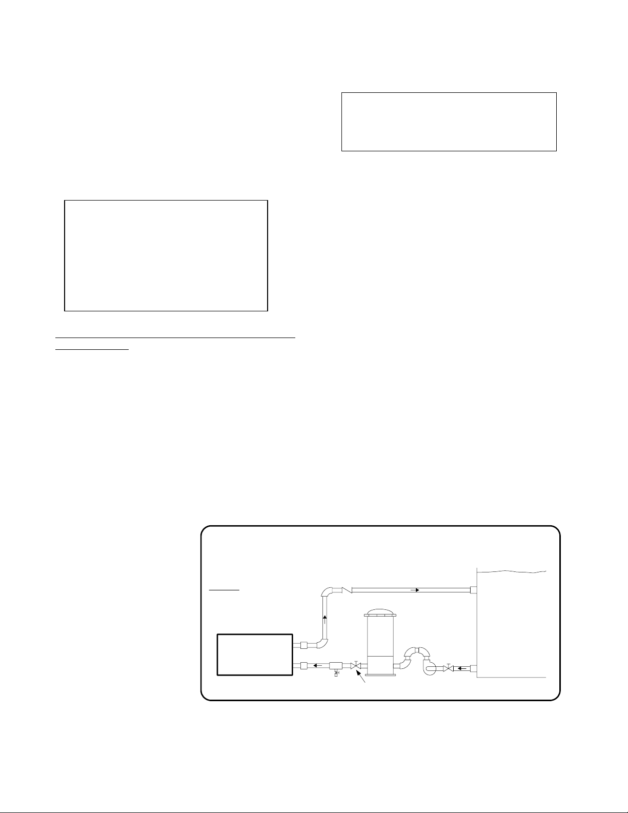
The Coates Spa Heater is suitable for indoor
installation. See Figure 1 for piping connections
and Figure 2 for electrical connections. Leave
minimum clearance of 4 inches on the top for
element removal and service access.
2.2 ELECTRICAL INSTALLATION
The electrical supply power must be single phase,
2 wire, 240 VAC. The supply must be protected
by a ground fault circuit interrupter (GFCI) in
accordance with NEC Article 680. An electrical
disconnect with over-current protection must be
provided. An insulated ground conductor must be
provided. See Figure 2 for electrical connections.
A lug has been provided for attachment of the
BONDING wire per the NEC Article 680-22, (a)(4).
This lug is located next to the conduit entrance.
** NOTICE **
NO PRESSURE RELIEF
VALVE IS SHIPPED WITH
THIS HEATER AND NONE
IS REQUIRED PER UL
STD 1261. DO NOT
INSTALL SHUT OFF
VALVE BETWEEN THE
HEATER AND POOL OR
SPA. A CHECK VALVE IS
ACCEPTABLE AND IN
ACCORDANCE TO UL STD
1261 REVISED JULY 1983.
DO NOT INSTALL ANY SHUT-OFF
VALVE ON DISCHARGE SIDE OF
HEATER. A SWING CHECK
VALVE IS PERMITTED.
Exception
pressure relief valve is installed
between the heater and valve, the
valve may be of the shut-off (ball or
gate) type.
CAUTION
: If a 30 psi (2.1 Kg/cm2)
COATES POOL
HEATER
FIGURE 1 – PIPING DIAGRAM
DRAIN
VALVE
CHECK
VALVE
FILTER
BALL OR GATE
VALVE
PUMP
BALL OR GATE
VALVE
POOL
or
SPA
 Loading...