

Page 1

POOL HEATER
INSTALLATION, OPERATION
AND MAINTENANCE
MODELS:
CE SERIES
12, 15 & 18kW
208V, 240V, 480V
BEFORE YOU BEGIN
CHECK ALL ELECTRICAL CONNECTIONS TO ALL COMPONENTS
WITHIN THE HEATER FOR TIGHTNESS. CONNECTIONS CAN
BECOME LOOSE DURING SHIPMENT AND HANDLING.
CPH SERIES
24 & 30kW
208V, 240V, 480V
PHS SERIES
36, 45, 54 & 57kW
208V, 240V, 480V
CAUTION
THE ELECTRICAL INSTALLATION MUST BE IN ACCORDANCE
WITH ARTICLE 680 OF THE NATIONAL ELECTRICAL CODE.
WARNING
Only qualified personnel, as defined by National Electric Code Article
100, should install and maintain this equipment. Unauthorized
alteration or improper maintenance of this unit may release the
manufacturer from any warranty claims. The installation must be in
accordance with the instructions in this manual and applicable local
plumbing and electrical codes.
Publication 11/13
Page 2

IMPORTANT SAFETY INSTRUCTIONS
Page 2
When using this electrical equipment, basic safety precautions should always be followed, including the
following.
1) READ AND FOLLOW ALL INSTRUCTIONS.
2) To reduce the risk of injury.
A) The water in a pool or tub should never exceed 104°F (40°C). A water temperature in excess of
104°F is considered unsafe for all persons. Lower water temperatures are recommended for
extended use (exceeding 10-15 minutes) and for young children.
B) Since excessive water temperatures have a high potential for causing fetal damage during the
early months of pregnancy, pregnant or possibly pregnant women should limit pool or tub water
temperatures to 100°F (38°C).
C) Before entering a pool or tub, the user should measure the water temperature at several occupant
locations using an accurate thermometer since the tolerance of water temperature-regulating
devices may vary as much as ± 5°F (± 3°C).
D) Alcohol, drugs or medications should not be used before or during pool or tub use since their use
may lead to unconsciousness with the possibility of drowning.
E) Obese persons and persons with a medical history of heart disease, low or high blood pressure,
circulatory system problems, or diabetes should consult a physician before using a pool or tub.
F) Persons using medication should consult a physician before using a pool or tub since some
medication may induce drowsiness while other medication may affect heart rate, blood pressure,
and circulation.
3) SAVE THESE INSTRUCTIONS.
---WARNING---
DANGER OF HYPERTHERMIA
Hyperthermia occurs when the internal temperature of the body reaches a level several degrees above
the normal body temperature of 98.6°F. The symptoms of hyperthermia include dizziness, fainting,
drowsiness, lethargy and an increase in the internal temperature of the body. The effects of hyperthermia
include:
a) Unawareness of impending hazard;
b) Failure to perceive heat;
c) Failure to recognize the need to exit pool or tub;
WARNING--- The use of alcohol, drugs or medications can greatly increase the risk of fatal
hyperthermia in pools and tubs.
d) Physical inability to exit pool or tub;
e) Fetal damage in pregnant women;
f ) Unconsciousness resulting in a danger of
drowning.
Page 3

WARNING
Page 3
Only qualified personnel, as defined by National
Electric Code Article 100, should install and
maintain this equipment. Unauthorized alteration
or improper maintenance of this unit may release
the manufacturer from any warranty claims. The
installation must be in accordance with the
instructions in this manual and applicable local
plumbing and electrical codes.
INTRODUCTION
This manual provides installation procedures,
operating and maintenance instructions and a parts list
for the Coates Pool Heater.
Your Coates Electric Swimming Pool Heater has been
designed and engineered to provide you with the most
progressive quality heating system possible. Its
operation is efficient and pollution-free. Models are
available for every size or make of pool.
To insure a long life of trouble-free service, your
Coates Pool Heater should be carefully installed in
accordance with the instructions given in this manual.
Failure to do so may damage the pool heater and the
pool equipment to which it is connected. Only
qualified personnel should install and maintain this
unit, and, of course, local plumbing and electrical
codes have precedence over these instructions.
1.0 DESCRIPTION
The Coates Swimming Pool Heater consists of a
heating tank with external enclosure, and the electrical
heating and control system. In order to help maintain
the heater in a satisfactory manner, a brief description
of its components and their operation is included for
the customer’s convenience.
The pressure vessel and its enclosure comprise the
main mechanical portion of the pool heater.
The pressure vessel, in conjunction with the flow
switch and heating element are the only portions of
this equipment in contact with the water.
The external enclosure is a sheet steel case totally
enclosing the pressure vessel and electrical
components. The enclosure is coated with a rust
inhibiting, powder coat finish.
The electrical system, which is the heart of this unit,
can be considered as three separate systems
engineered to provide optimum use of energy. They
are as follows:
(1) The heating elements; mounted on a four-bolt
flange. There are 2, 3 or 4 elements.
(2) The control system; consists of the pilot switch,
high limit thermostat, flow switch, temperature control,
magnetic contactors, 240V transformer (480V units only)
and sequencer (on some single phase units only).
These controls are wired into a control circuit designed
to control the temperature of the water leaving the
heater. The high-limit thermostat is designed to open
the control circuit and cut off the power in the event of
excessive temperature.
A flow switch is built-in to prevent the pool heater from
operating without water flow. The flow switch will
activate at flow rates of 20 GPM or greater.
(3) The main current-carrying components; are
the contactors and fuses. These are wired into circuits
which carry the full amperage draw of the elements.
The contactors open during a high temperature condition
to de-energize the elements.
The element fuses in these units are rated at 60 Amps
and have an interrupting capacity of 100,000 Amps rms.
These fuses provide supplemental circuit protection for
the internal wiring of the heater.
The heater has a temperature controller adjustable up to
104°F(40°C) and has one manual reset type high
temperature limit thermostat set at 118°F (48°C).
2.0 LOCATION AND PLUMBING
A. Installation: Location
Coates swimming pool heaters are quiet, do not expel
exhaust fumes, and may be conveniently located in a
shed or basement. Normal positioning of the pool
heater should be in close proximity to the pool filtration
system. Select a location conveniently close to
incoming electrical service and where excessively long
piping runs are not required.
Minimum clearance:
Front 36 (914)# 36 (914)#
Left 18 (457) 4 (102)
Right * 4 (102)
Top 18 (457) 20 (508)
Back 6 (153) *
* Required clearance is based on plumbing configuration used.
# Refer to NEC Table 110.26 (A)(1)
- Dimensions: Inches (mm)
- Temperature control is located on the front side.
PHS/CPH CE
Page 4
B. Installation: Plumbing
Page 4
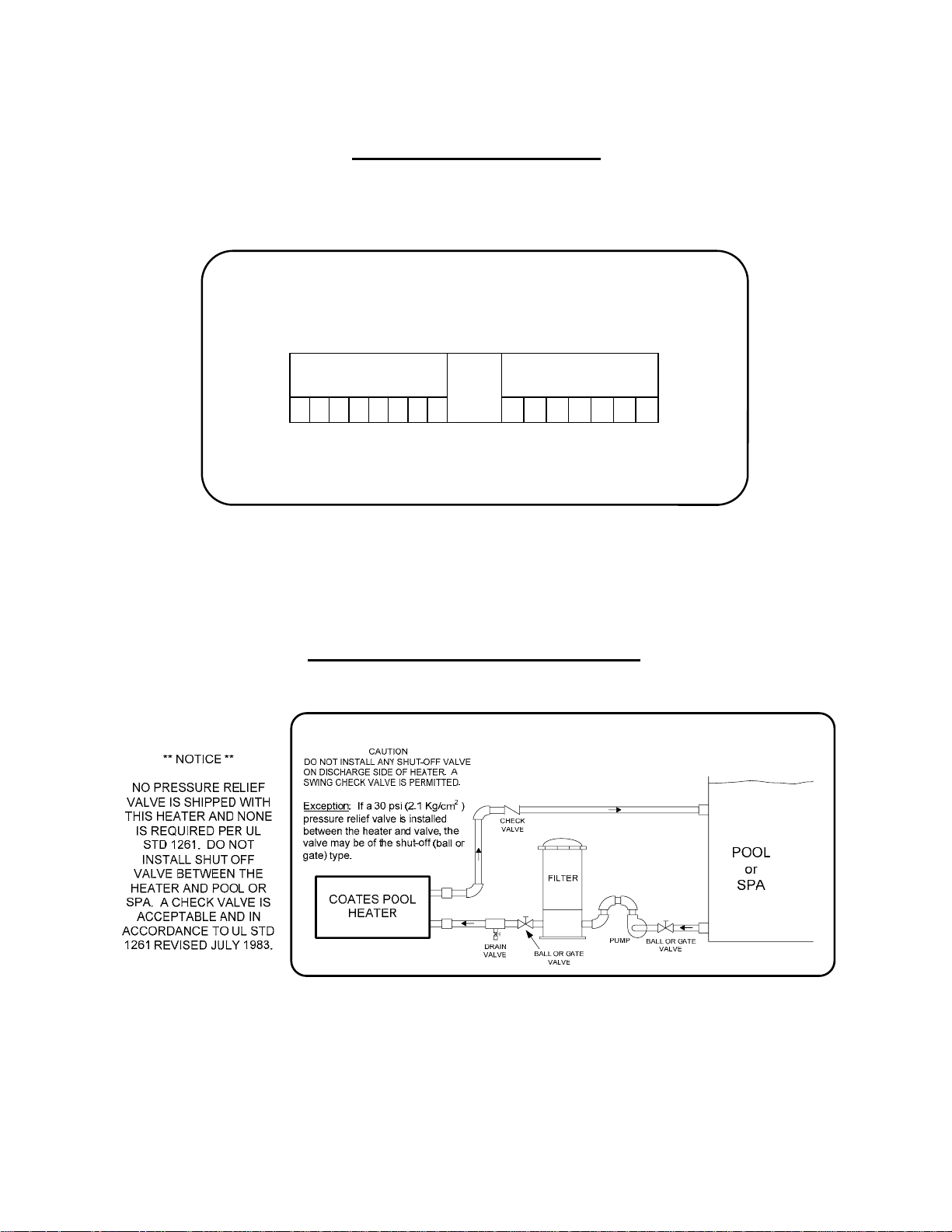
Pipe the heater as shown in Figure 2 to the inlet and
outlet openings on the right side. Connect the heater
in line between the filter discharge and pool. The
water line coming from the filter should be connected
to the heater inlet, and the discharge line to the pool
should be connected to the outlet. The pool will not
heat properly unless it is plumbed correctly. If plastic
pipe is used, it should be suitable for at least 120°F
(49 °C).
A plumbing bypass around the pool heater is not
necessary unless flow rate though the heater exceeds
80 GPM. A minimum flow rate of 20 GPM is required.
Lack of sufficient flow will not allow the flow switch to
activate the heater.
It may be necessary, in larger Olympic-sized or public
pools, to use two or more heaters to obtain sufficient
KW capacity. If so, the heaters must be placed in
parallel, so that each heater takes equal flow.
DRAINAGE: A method of draining water away from
the heater and other equipment is to be provided. The
heater should be flushed at the end of each swimming
season. During flushing or service, water may be
spilled and could cause damage to the floor or other
equipment. A drain valve is to be installed in the
INLET plumbing.
3.0 ELECTRICAL INSTALLATION
1. Check nameplate rating to insure the heater
matches your electrical supply.
2. CHECK ELECTRICAL CONNECTIONS TO ALL
COMPONENTS within the heater for tightness.
These can become loose during shipment and
handling.
3. Check components for any moisture, rust, or dust
which may have accumulated during shipping, and
clean or dry where necessary.
All pool heaters covered in this manual have integral
thermostats, transformers, contactors and sequencers
where required.
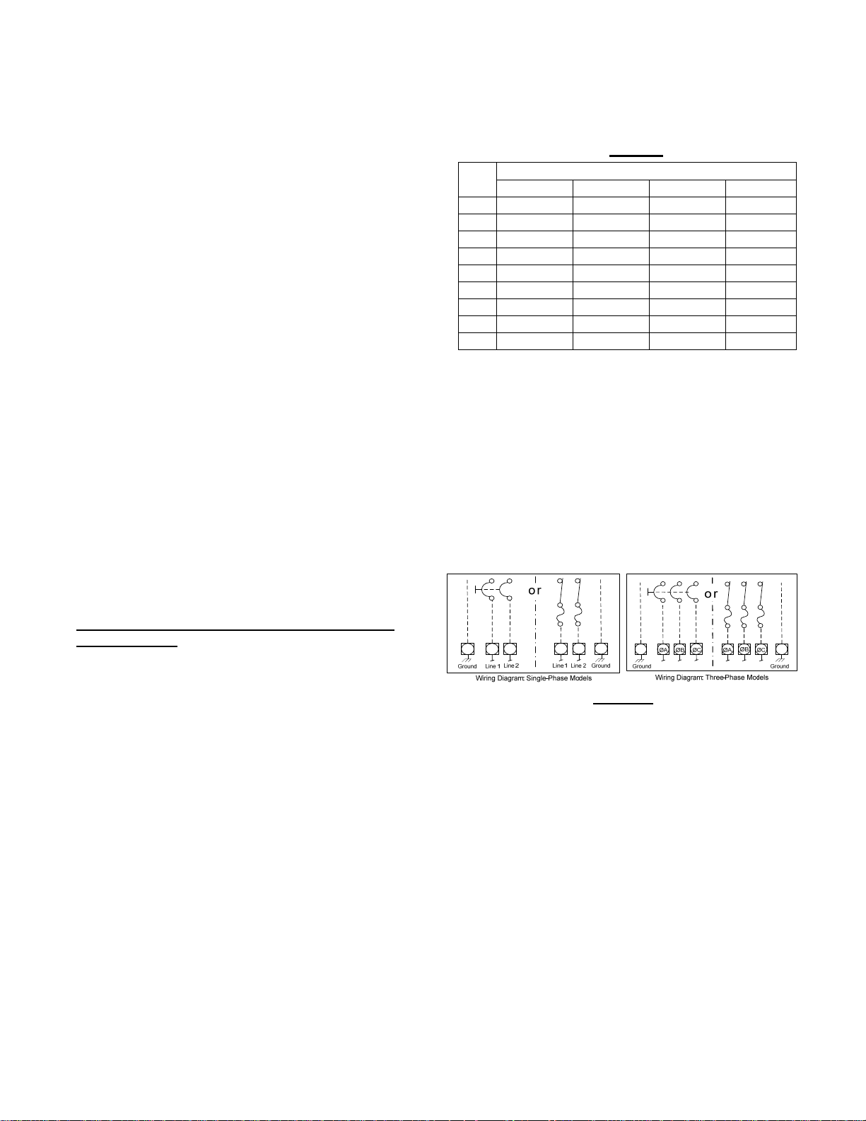
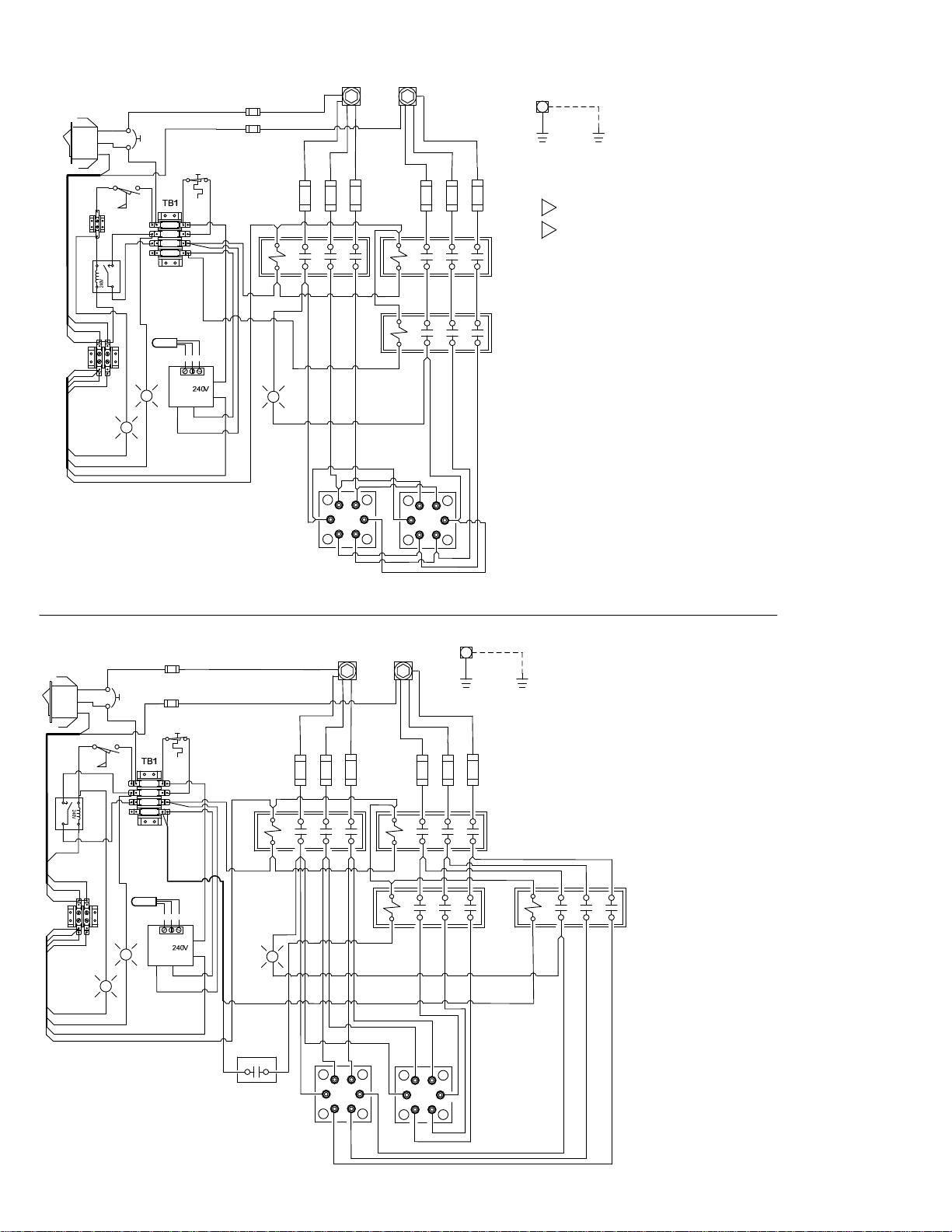
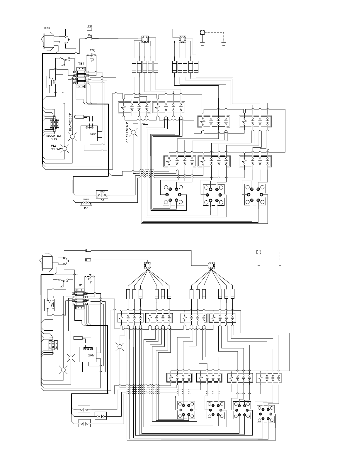
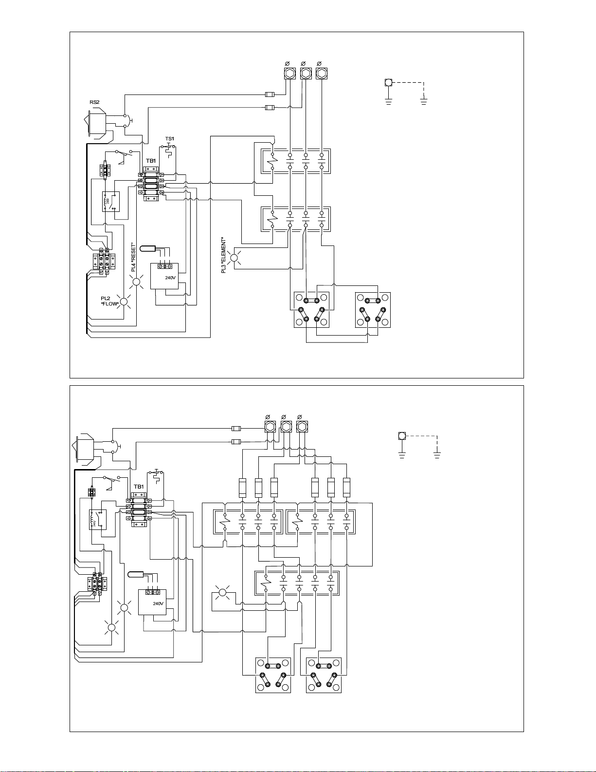
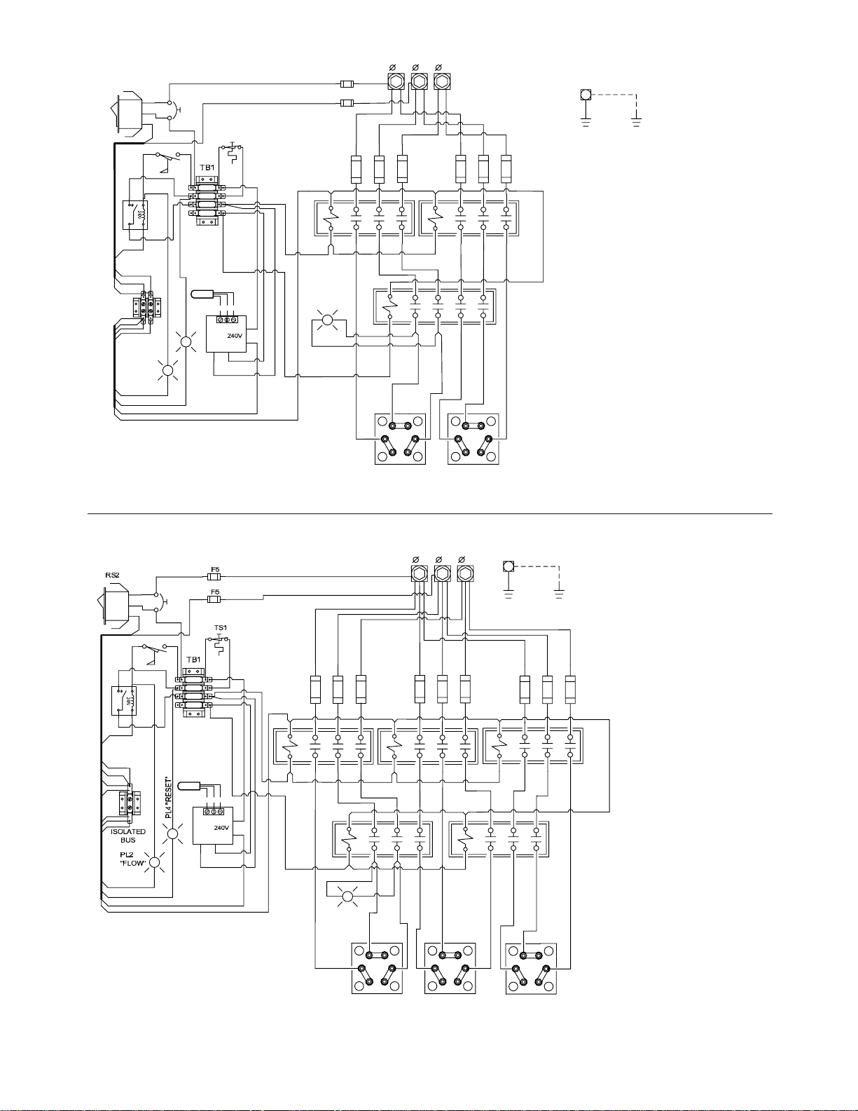
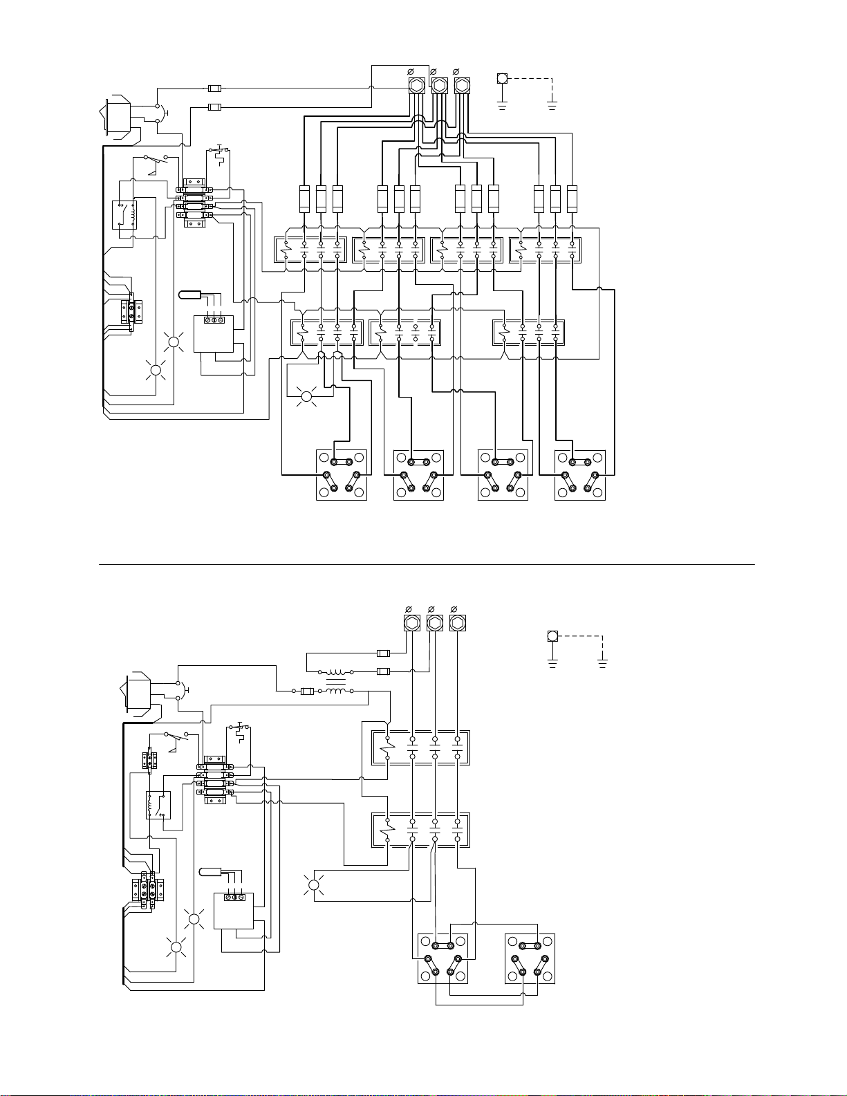
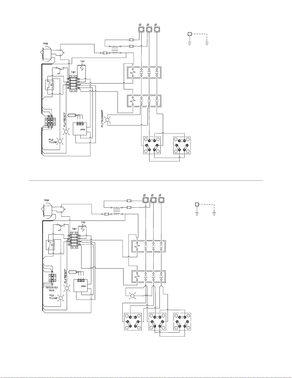
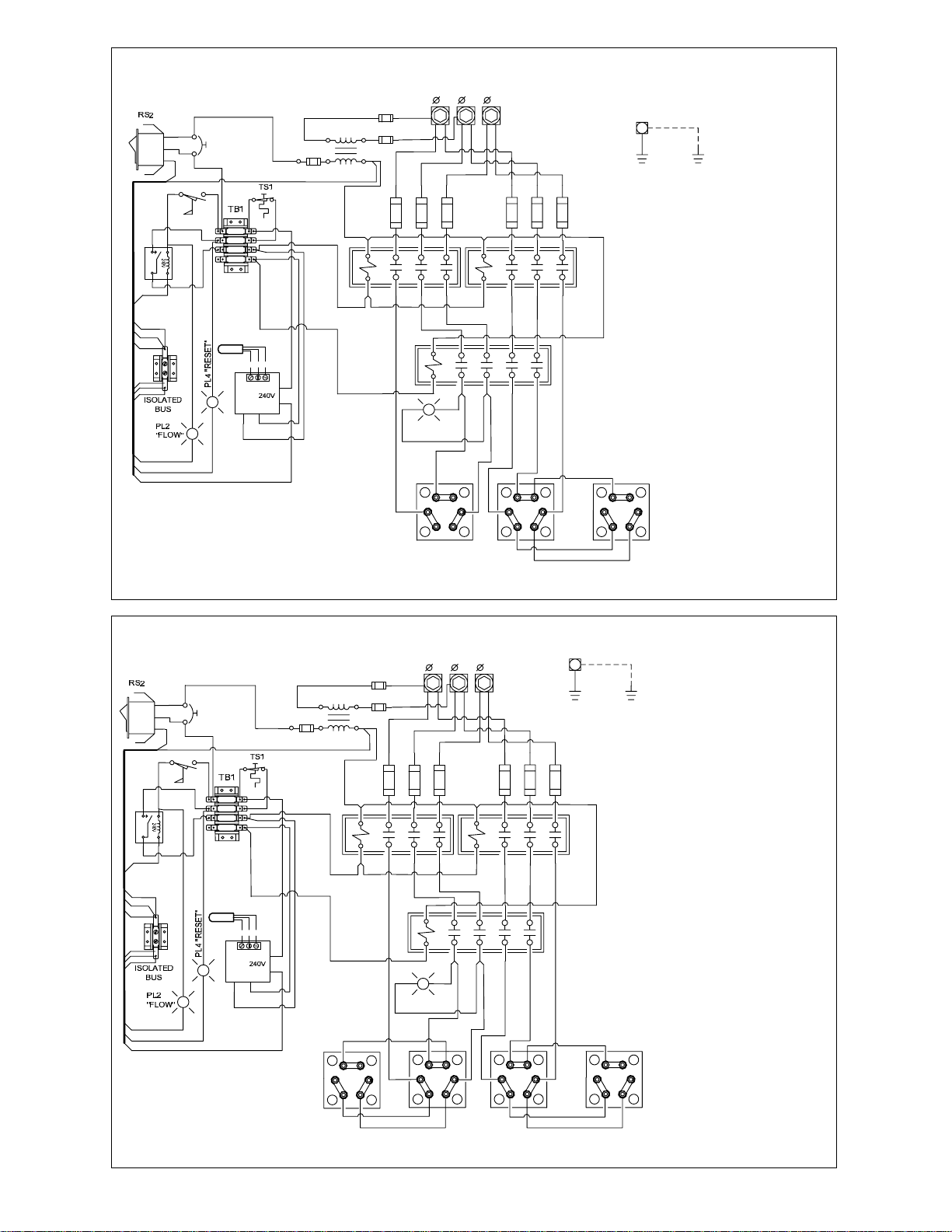
Wiring diagrams included show internal wiring and
required field connections for various models. Consult
your local electrical code for proper wire and conduit
sizes, and other local requirements.
Do not connect the pool heater to, or operate at, a
voltage other than the voltage rated on the nameplate.
Bring wires of adequate size from a fused disconnect
switch or circuit breaker with an ampere rating of
125% of the ampere rating shown on heater
nameplate. Refer to Table 1 for wire sizes. Connect
power conductors to the power distribution block inside
the heater. All other internal connections are completed
and tested at the factory.
Ground wires must be insulated copper conductor and
the same size as supply wiring, but not less than #12
AWG.
Table 1
KW
240V/1Ø 208V/3Ø 240V/3Ø 480V/3Ø
WIRE SIZE: AWG
12 4 8 8 12
15 4 6 8 10
18 3 4 6 10
24 1 3 4 8
30 2/0 2 3 8
36 3/0 1 2 8
45 250MCM 2/0 1/0 4
54 350MCM 3/0 2/0 3
57 350MCM 3/0 2/0 3
Suggested size for insulated copper conductor
wires. Based on 125% correction factor for wire
with 75°C insulation.
A. To Connect Pool Heater to Power Supply
The pool heaters with load ratings over 48 Amps have
branch supplemental fusing already installed in the
element circuitry; see wiring diagrams. To connect to
the power supply, one needs only to protect the main
supply lines, either with a circuit breaker or fused
disconnect switch (Figure 1). Suggested wire sizes are
shown in Table 1.
Figure 1
B. Startup Procedure:
1. Make sure that the pump is on and that there is at
least 20 GPM flow through the pool heater. The
heating elements will fail prematurely if allowed to
operate with insufficient water flow.
2. Check temperature control setting, also, examine
wiring for loose connections, etc.
3. Turn on power at main disconnect switch.
4. Turn on pilot switch on pool heater.
If the high temperature manual reset high limit switch
shuts off the heater, disconnect power at disconnect
switch and determine the cause before resetting.
Page 5

4.0 CONTROL PANEL
Page 5
A. INDICATOR LIGHTS
The control has three indicator lights and a lighted ONOFF rocker switch. The lights are as follows:
STATUS LIGHTS
LIGHT DESCRIPTION (when Illuminated)
ON-OFF Heater has power to control circuit.
RESET High Temperature limit is OK.
FLOW Sufficient water flow through heater.
ELEMENT Heating elements are powered.
B. DIGITAL THERMOSTAT CONTROL
For heaters equipped with a digital thermostat. The
digital thermostat control which measures the
temperature of the water as it enters the heater has a
MENU button, up and down adjustment buttons, and
an LED display. The desired water temperature (set
point) is controllable between 40°F and 104°F (5°C
and 40°C). The set point may differ from the actual
water temperature at the pool or spa due to heat loss
in the piping.
MENU:
The MENU button cycles through the three menu
items: Measured Water Temperature (default), SET
POINT and °F/°C.
ADJUSTING THE SET POINT:
Press one of the following buttons; MENU,
The display will momentarily blank and then the
current set point will be displayed. Press the
button to change the set point. Hold the button down
for rapid temperature changes.
The set point will be saved and the display will return
to the measured temperature after two seconds of
inactivity.
OPERATION:
In the measured temperature mode, the water
temperature in the heater is displayed. The LED
corresponding to the current temperature scale will be
illuminated. If the heater is calling for heat the
HEATING LED will be illuminated.
or .
or
FAHRENHEIT TO CELCIUS:
Press the MENU button twice and the current
temperature scale will be displayed ( F or C ). Press the
or buttons to toggle between F and C.
The temperature scale will be saved and the display will
return to the measured temperature after two seconds of
inactivity.
ERROR CODE:
The display will read “Err” when it detects a problem with
the temperature sensor. This can be caused by a faulty
sensor or a loose connection between the sensor and
the temperature controller.
5.0 MAINTENANCE
Element Inspection and Replacement:
1. Turn off power at main disconnect switch and turn
off pump.
2. Drain pool heater.
3. Remove service access panel opposite inlet/outlet.
4. Disconnect element wires.
5. Remove the four (4) element flange retaining nuts
and extract element.
6. Installation is the reverse of steps 1 through 5.
(Reinstall element with new gasket)
When closing down the pool for any length of time, shut
off the power at the main disconnect switch and drain
the water from the system. Water must not be allowed
to freeze in the heater, as this will cause severe
damage.
Annual Cleaning:
Yearly, before winter, the pool heater should be drained
and cleaned to remove any scale or sludge. More
frequent cleaning may be required if pool water contains
sediment or any amount of foreign matter.
1. Turn off heater at main disconnect switch.
2. Open drain valve.
3. Permit water to run until it is clear.
4. Close valve and restart normally.
Page 6
S
H
7P
85
S
H
34
4P
5
S
H
348
5P
4
348
34836PHS
CPH
0
H
3483
24CP
48
3
E
34818CE
15C
8
THREE PHASE 480V
34
481
3
457
2
3
54
24
3
45
24
3
3243
2430CPH
3
24CPH
4
32
3241
THREE PHASE 240V
32415C
41
32
57PHS
0
32
32054PHS
32045PHS
HEATER MODEL No.
3
320
30
320
2
320
01
32
15
THREE PHASE 208V
320
32012CE
45
12
5
124
4
124
3
SINGLE PHASE 240V
124
124
124
124
1
1
24
241
30
24
1
15
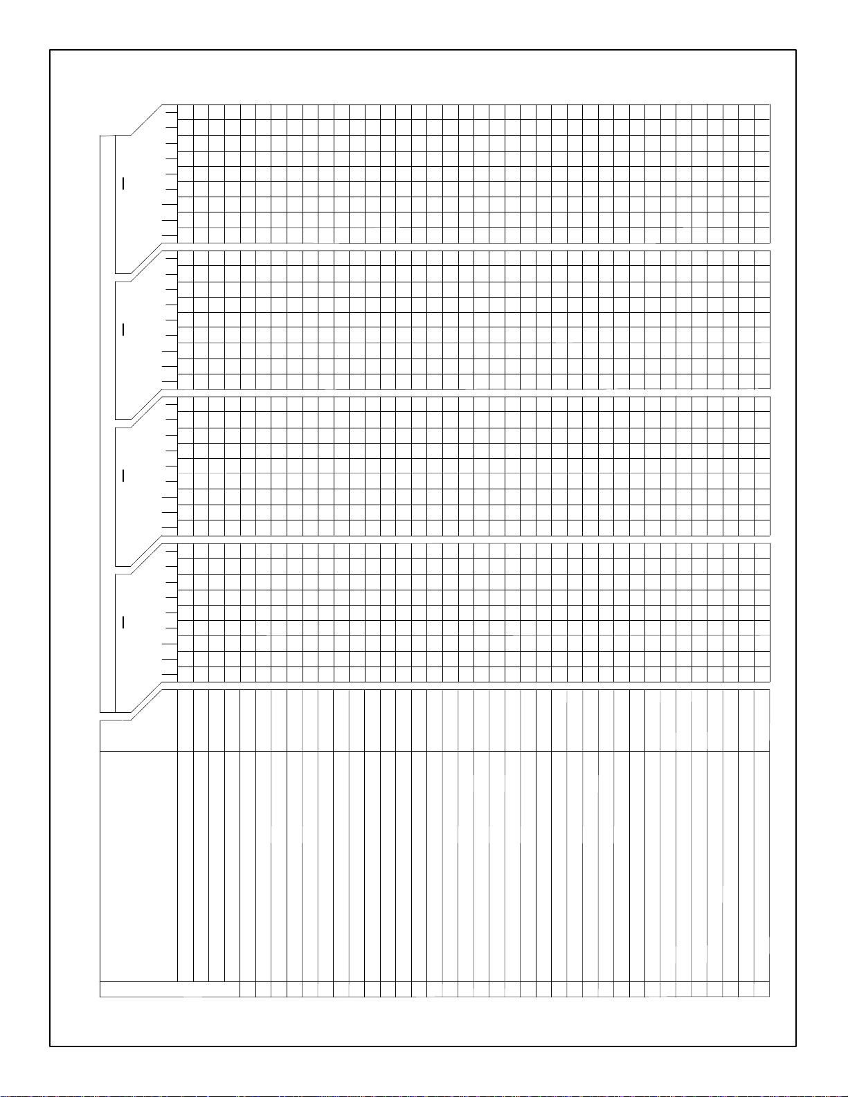
MODELS CE, CPH & PHS
POOL HEATER PARTS LIST
2C
P
P
P
P
6
CE
8
2C
6PHS
C
4C
8C
CE
7PHS
4PHS
5PHS
6PHS
CPH
C
8C
CE
CE
2
12 15 18 3624 30 45 54 57
E
S
H
S
H
S
H
S
H
E
E
H
P
H
P
E
30 37 45 59 74 89 111 130 137 15 19 22 29 37 69655544
12 15 18 3624 30 45 54 57
12 15 18 3624 30 45 54 57
H
P
E
222223 22222 22222 2 222233443333344 44 44
51 64 77 102128 153 191 225238 34 5042 67 84 101 126 150 158
12 15 18 3624 30 45 54 57
222222
222222222 22222 2222 222222222 222
66 666666 66 66612121212 12 1210 10 9 9 9 9
1111 11
111
111111111
1
2
3
23
3
111
POOL HEATER PARTS LIST- N
2
2
12
111111 111
22222 22 22
21
1
2
23
3
222222
222222222
77
5522
3
2
2
12
21
1
2
23
77
3
3
2
2
11 11
1
12
21
3333 3333333 33333333333
1
2
3
23
3
4444
2233
2
2
44 77 882255
12
33 333
1 1 111 1 111 1 11111111111111111111111111
1 111 1 1 111111111111111111111111111111
1 111 1 1 111111111111 1 11111111111111111
1 111 1 1 111111111111111111111111111111
21
222 222 222 22222 222244 44 444444422 4
333
PART No.
COMPONENTS
TOTAL kW PER HEATER
AMPERAGE AT FULL LOAD
ELEMENTS PER HEATER
ILLUSTRATION ITEM No.
29018910
FUSE, F-1, SC-60, 60A/480V
18
22002150
29034620
29034648
23001521
22003820
20006036
20006029
20006003
20006004
20006046
20006039
20006009
20006010
20006056
22012200
23000105
29016310
29016305
TS-3 DIGITAL POOL STAT8
PL-1, 2 & 4, PILOT LIGHT, AMBER 120/240V
PL-3, PILOT LIGHT, AMBER 480V
RS-2 ROCKER SWITCH, LIGHTED 240V
TS-1 HIGH TEMP. LIMIT
ELEMENT, 6 kW, 208V12
ELEMENT, 9 kW, 208V12
ELEMENT, 12 kW, 208V12
ELEMENT, 15 kW, 208V12
ELEMENT, 6 kW, 240V12
ELEMENT, 9 kW, 240V12
T5, XFMR 480V/240V-50VA
FLOW SWITCH
FUSE, F-5, FNQ-R-1, 1A/600V
FUSE, F-6, FNQ-R-1/2, 0.5A/600V
9
3
4
7
6
9
10
11
ELEMENT, 12 kW, 240V12
20006049
ELEMENT, 15 kW, 240V12
ELEMENT, 6 kW, 480V12
ELEMENT, 9 kW, 480V12
44000250
20006015
20006016
ELEMENT, 12 kW, 480V12
ELEMENT, 15 kW, 480V12
21005505
21006010
21001000
21001300
ELEMENT GASKET
K-7 SEQUENCE TIMER 1-POLE 1 1
RELAY, 30AMP, SPST, NO 1 1 1 1 1 1 1 11 1 11111111 1 11111111 1 11111111
CR-7 CONTACTOR 3P, 208/240V COIL
13
17
16 CR-8 CONTACTOR 4P, 208/240V COIL
15
14
Page 7
DPH-ILL D
Page 7
7
4
3
2
5
6
1
8
19
13
12
18
17
16
15
14
9
10
20
11
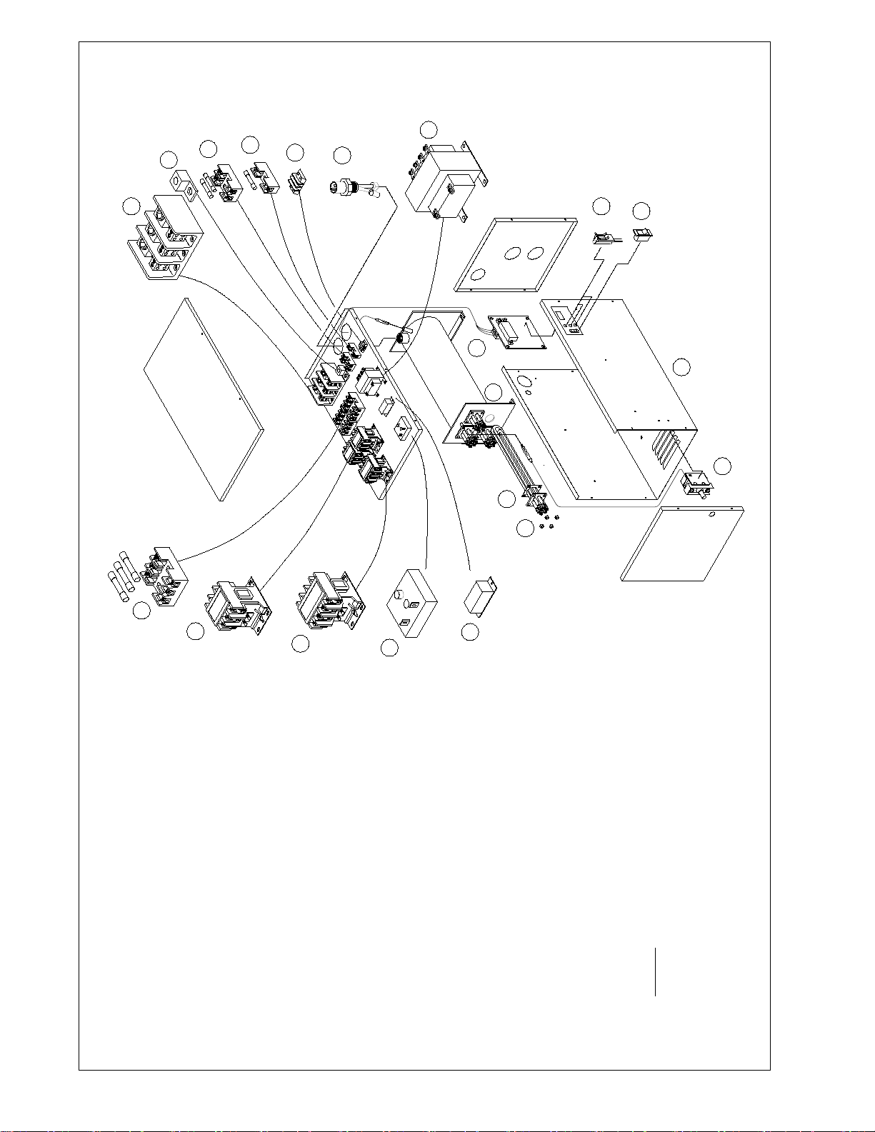
1. POWER DISTRIBUTION BLOCK
2. GROUND LUG
3. CONTROL TRANSFORMER PRIMARY FUSING
4. CONTROL TRANSFORMER SECONDARY FUSING
5. EXTERNAL CONTROL CONNECTION
6. FLOW SWITCH
7. CONTROL TRANSFORMER (WHEN REQUIRED)
8. TEMPERATURE CONTROL
9. PILOT LIGHTS – ELEMENT, FLOW, RESET
10. PILOT SWITCH, LIGHTED "ON/OFF"
11. TEMPERATURE LIMIT SWITCH
12. HEATING ELEMENT
13. HEATING ELEMENT GASKET
14. FLOW RELAY
15. SEQUENCE TIMER (WHEN REQUIRED)
16. CONTACTOR (4-POLE)
17. CONTACTOR (3-POLE)
18. HEATER CIRCUIT FUSING
19. VESSEL
20. ENCLOSURE
NOTE:
REFERENCE THE POOL HEATER PARTS LIST FOR
COMPONENT PART NUMBERS AND QUANTITIES.
Page 8
WATER CHEMISTRY
Page 8
PROTECTING YOUR COATES HEATER
WITH PROPER WATER CHEMISTRY
Proper water balance is important to extending the life of your Coates
Heater. While pH control is critical, the control of alkalinity and calcium
hardness will protect against scaling and also help to prevent corrosion.
ACID
HEATER
CAN BE
DAMAGED
The correct level of sanitizer, pH, total alkalinity and calcium hardness will very, depending
on the type of pool (plaster, fiberglass or vinyl) and the chemical content of the fill water.
Water that is out of balance can damage your pool heater and void the warranty. This
CORROSIVE
WATER
0 1 2 3 4 5 6 7
heater is not for use in salt water pools.
IDEAL
RANGE
7.2-7.8
PLUMBING CONNECTIONS
ALKALINE
ALKALINE
WATER
8 9 10 11 12 13 14
HEATER
CAN BE
DAMAGED
Page 9
RS2
Page 9
BRASS
#1
COPPER
#3
ALUMINUM
K8
ISOLATED
BUS
#2
PL2
"FLOW"
FLOW
NOCOM
HEATER GROUND
F5
TERMINAL
F5
ENCLOSURE
TS1
#8
#8
#8
#8
#8
GROUND
#8
F1 F1 F1 F1 F1 F1
1
234
COIL
CR7
#8
TEMP
W R
B
TS3
CNO
J4
J1
J9
AC
J2
AC
PL1 "ELEMENT"
RB
W
RB
PL4 "RESET”
J3
#10
COIL
#8#8
COIL
#10
#10
#10
RB
W
WW
RB
#10
#10
HEATING ELEMENTS
CR7
CR7
#8
#8#8
POOL
GROUND
FLOW SWITCH
1
TB1 FOR REMOTE TEMPERATURE
2
CONTROL (IF USED).
3.
SEE INSTRUCTION MANUAL FOR COMPONENT
IDENTIFICATION.
4.
ALL WIRING TO BE 105°C INSULATED, MINIMUM.
CONTROL CIRCUIT WIRING; 14 AWG.
POWER CIRCUIT WIRING; AS NOTED.
LEGEND;5.
R = RED
B = BLACK
W = WHITE
6. HEATING ELEMENT QTY/RATING;
12kW = 2 @ 6kW
15kW = 1 @ 6kW & 1 @ 9kW
18kW = 2 @ 9kW
MODEL CE
SINGLE PHASE
208V – 12, 15 & 18kW
240V – 12, 15 & 18kW
1BC1218G
RS2
BRASS
#1
COPPER
#3
ALUMINUM
NO COM
ISOLATED
BUS
#2
PL2
"FLOW"
HEATER GROUND
TERMINAL
F5
1.
F5
ENCLOSURE
GROUND
POOL
GROUND
TS1
FLOW
1
234
#8
#8
#8
#8
#8
F1 F1 F1 F1 F1 F1
#8
K8
TEMP
PL4 "RESET”
TS3
CNO
J3
COIL
1
#10 #10 #10
RB
W
RB
CR7
W R
B
J1
J9
AC
J2
AC
J4
PL1 "ELEMENT"
K7
TIMER
3
COIL
COIL
W
WW
#10 #10 #10
RB
RB
CR7
CR7
CR7
COIL
TB1 FOR REMOTE TEMPERATURE
CONTROL (IF USED).
2.
SEE INSTRUCTION MANUAL FOR COMPONENT
IDENTIFICATION.
3.
ALL WIRING TO BE 105°C INSULATED, MINIMUM.
CONTROL CIRCUIT WIRING; 14 AWG.
POWER CIRCUIT WIRING; AS NOTED.
LEGEND;4.
R = RED
B = BLACK
W = WHITE
#10 #10
#10
MODEL CPH
SINGLE PHASE
208V – 24 & 30kW
240V – 24 & 30kW
HEATING ELEMENTS
1BC2430H
Page 10
#2
Page 10
BRASS
#1
COPPER
#3
ALUMINUM
NO COM
FLOW
K8
HEATER
GROUND
ENCLOSURE
#8 #8
#8
#8
F1
F1F1F1
#8
F1
1
234
#8 #8
F1F1
#8 #8
F1F1F1
#8
GROUND
TERMINAL
POOL
GROUND
TB1 FOR REMOTE TEMPERATURE
1.
CONTROL (IF USED).
2.
SEE INSTRUCTION MANUAL FOR COMPONENT
IDENTIFICATION.
3.
ALL WIRING TO BE 105°C INSULATED, MINIMUM.
CONTROL CIRCUIT WIRING; 14 AWG.
POWER CIRCUIT WIRING; AS NOTED .
LEGEND;4.
R = RED
B = BLACK
W = WHITE
RS2
ALUMINUM
BRASS
COPPER
NO COM
CR7
COIL
CR7
COIL
RB
W
#10
#10
#10
F1
COIL
RB
CR7
CR7
COIL
#10
COIL
CR7
RB
W
WW
RB
COIL
CR7
#10
#10 #10
COIL
CR7
RB
WW
RB
CR7
CR7
MODEL PHS
SINGLE PHASE
208V – 36 & 45kW
240V – 36 & 45kW
1BC3645G
F1 F1
COIL
HEATING ELEMENTS
F1 F1
F1
COIL
CR7
HEATER
GROUND
TB1 FOR REMOTE TEMPERATURE
1.
F1
CONTROL (IF USED).
2.
SEE INSTRUCTION MANUAL FOR COM PONENT
IDENTIFICATION.
3.
ALL WIRING TO BE 105°C INSULATED, MINIMUM.
CONTROL CIRCUIT WIRING; 14 AWG.
POWER CIRCUIT WIRING; AS NOTED.
LEGEND;4.
R = RED
B = BLACK
W = WHITE
CR7
ENCLOSURE
GROUND
TERMINAL
POOL
GROUND
COIL
TEMP
W R
B
J1
J9
AC
TS3
J2
AC
CNO
J4
J3
F5
#2
#1
#3
F5
TS1
FLOW
F1 F1 F1
1
234
F1 F1
K8
COIL
ISOLATED
BUS
PL2
"FLOW"
TEMP
PL4 "RESET”
W R
B
J9
AC
TS3
AC
CNO
J4
J3
K7
TIMER
31
TIMER
31
K7
J1
J2
TIMER
31
K7
PL1 "ELEMENT"
COIL
W
#10
#10
#10
#10
RB
RB
COIL
CR7
W
HEATING ELEMENTS
COIL
CR7
RB
WW
RB
CR7
RB
WW
RB
WW
COIL
RB
RB
CR7
MODEL PHS
SINGLE PHASE
208V – 54 & 57kW
240V – 54 & 57kW
1BC5457H
Page 11
BRASS
Page 11
#1
COPPER
#3
ALUMINUM
BA
C
#8
F5
#8 #8
F5
#2
HEATER GROUND
TERMINAL
ENCLOSURE
GROUND
POOL
GROUND
FLOW
RS2
ALUMINUM
BRASS
COPPER
K8
K8
ISOLATED
#2
#1
#3
ISOLATED
BUS
PL2
"FLOW"
BUS
FLOW
NOCOM
1
234
NO COM
#8
COIL C OIL
#8
TEMP
W R
B
J1
J9
AC
TS3
J2
AC
CNO
J4
J3
F5
F5
#8
RB
WW
RB
BA
C
#8 #8
TS1
F1 F1 F1
1
234
COIL
#8 #8
TEMP
W R
B
TS3
CNO
J3
J1
J9
AC
J2
AC
J4
PL4 "RESET”
PL1
"ELEMENT"
COIL
COIL
CR7
#8 #8 #8
CR7
#8 #8
CR7
#8 #8
#10
#10
HEATING ELEMENTS
F1 F1
F1
#8
CR8
#8
#8#8 #8
#10
1.
TB1 FOR REMOTE TEMPERATURE CONTROL (IF USED).
2.
SEE INSTRUCTION MANUAL FOR COMPONENT
IDENTIFICATION.
3.
ALL WIRING TO BE 105°C INSULATED, MINIMUM.
CONTROL CIRCUIT WIRING; 14 AWG.
POWER CIRCUIT WIRING; AS NOTED.
LEGEND;4.
R = RED
B = BLACK
W = WHITE
BR
CR7
WW
BR
HEATER GROUND
TERMINAL
ENCLOSURE
GROUND
1.
TB1 FOR REMOTE TEMPERATURE CONTROL (IF USED).
2.
SEE INSTRUCTION MANUAL FOR COMPONENT
IDENTIFICATION.
ALL WIRING TO BE 105°C INSULATED, MINIMUM.
3.
CONTROL CIRCUIT WIRING; 14 AWG.
POWER CIRCUIT WIRING; AS NOTED.
LEGEND;
4.
R = RED
B = BLACK
W = WHITE
MODEL CE
THREE PHASE
208V – 12 & 15kW
240V – 12, 15 & 18kW
POOL
GROUND
3BC1218F
RB
WW
RB
HEATING ELEMENTS
BR
WW
BR
MODEL CE
THREE PHASE
208V – 18kW
3B18F
Page 12
RS2
Page 12
BRASS
#1
COPPER
#3
ALUMINUM
NO COM
ISOLATED
BUS
#2
PL2
"FLOW"
BA
F5
F5
#8
C
#8 #8
TS1
FLOW
1
F1 F1 F1
234
K8
TEMP
W R
B
TS3
CNO
J4
J1
J9
AC
J2
AC
PL4 "RESET”
J3
COIL
PL1
"ELEMENT"
#8 #8
#8 #8 #8
COIL
F1 F1
COIL
CR7
F1
CR7
#8
CR8
#8
#8#8 #8
HEATER GROUND
TERMINAL
ENCLOSURE
GROUND
1.
TB1 FOR REMOTE TEMPERATURE CONTROL (IF USED).
2.
SEE INSTRUCTION MANUAL FOR COMPONENT
IDENTIFICATION.
ALL WIRING TO BE 105°C INSULATED, MINIMUM.
3.
CONTROL CIRCUIT WIRING; 14 AWG.
POWER CIRCUIT WIRING; AS NOTED.
LEGEND;
4.
R = RED
B = BLACK
W = WHITE
POOL
GROUND
#2
BRASS
#1
COPPER
#3
ALUMINUM
NO COM
FLOW
K8
TEMP
1
23
4
TS3
CNO
RB
WW
RB
HEATING ELEMENTS
#8
CR7
COIL
#8 #8
F1 F1
CR7
#8
F1 F1 F1
COIL
#8 #8
W R
B
J1
J9
AC
J2
AC
J4J3
#8 #8 #8
COIL
BR
WW
BR
MODEL CPH
THREE PHASE
208V – 24 & 30kW
240V – 24 & 30kW
3BC2430G
HEATER GROUND
C
#8
CR7
TERMINAL
ENCLOSURE
GROUND
COIL
#8 #8
F1 F1
#8 # 8
#8
POOL
GROUND
F1
#8
CR7
TB1 FOR REMOTE TEMPERATURE
1.
CONTROL (IF USED).
2.
SEE INSTRUCTION MANUAL FOR COMPONENT
IDENTIFICATION.
3.
ALL WIRING TO BE 105°C INSULATED, MINIMUM.
CONTROL CIRCUIT WIRING; 14 AWG.
POWER CIRCUIT WIRING; AS NOTED .
LEGEND;4.
R = RED
B = BLACK
W = WHITE
CR7
BA
#8
F1
#8
COIL
PL1 "ELEMENT"
WW
RB
RB
BR
WW
BR
HEATING ELEMENTS
RB
WW
RB
MODEL PHS
THREE PHASE
208V – 36 & 45kW
240V – 36 & 45kW
3BC3645G
Page 13
RS2
Page 13
#2
BRASS
#1
COPPER
#3
ALUMINUM
NO COM
240V
ISOLATED
BUS
PL2
"FLOW"
K8
FLOW
HEATER GROUND
#8
ENCLOSURE
GROUND
CR7
TERMINAL
COIL
POOL
GROUND
TB1 FOR REMOTE TEMPERATURE
1.
CONTROL (IF USED).
2.
SEE INSTRUCTION MANUAL FOR COMPONENT
IDENTIFICATION.
3.
ALL WIRING TO BE 105°C INSULATED, MINIMUM.
CONTROL CIRCUIT WIRING; 14 AW G.
POWER CIRCUIT WIRING; AS NOTED.
LEGEND;4.
R = RED
B = BLACK
W = WHITE
CR7
TB1
1
23
4
BA
F5
F5
#8
C
#8
TS1
COIL
F1 F1 F1
CR7
F1
F1 F1
COIL
F1 F1 F1 F1 F1 F1
CR7
COIL
TEMP
W R
B
TS3
CNO
J3
J1
J9
AC
240V
J2
AC
J4
COIL
PL4 "RESET”
CR7
COIL
CR7
COIL
CR7
PL1 "ELEMENT"
#2
BRASS
#1
COPPER
#3
ALUMINUM
K8
ISOLATED
BUS
FLOW
NO COM
TEMP
1
234
TS3
CNO
RB
WW
RB
RB
WW
RB
RB
WW
RB
RB
WW
RB
HEATING ELEMENTS
BA
C
#8
#8 #8
#8 #8
CR7
#8
240V
F5
T5
XF
X3 X1
F6
F5
COIL COIL
CR7
#8
#8 #8
W R
B
J1
J9
AC
J2
AC
J4J3
RB
WW
RB
#10
#10
#10
HEATER GROUND
TERMINAL
ENCLOSURE
GROUND
1.
TB1 FOR REMOTE TEMPERATURE CONTROL (IF USED).
2.
SEE INSTRUCTION MANUAL FOR COMPONENT
IDENTIFICATION.
3.
ALL WIRING TO BE 105°C INSULATED, MINIMUM.
CONTROL CIRCUIT WIRING; 14 AWG.
POWER CIRCUIT WIRING; AS NOTED .
LEGEND;4.
R = RED
B = BLACK
W = WHITE
BR
BR
POOL
GROUND
WW
MODEL CE
THREE PHASE
480V – 12, 15 & 18kW
HEATING ELEMENTS
MODEL PHS
THREE PHASE
208V – 54 & 57kW
240V – 54 & 57kW
3BC5457J
3J1218J
Page 14
#2
Page 14
BRASS
#1
COPPER
#3
ALUMINUM
FLOW
240V
BA
C
#8
F5
T5
XF
X3 X1
F6
F5
#8 #8
HEATER GROUND
TERMINAL
ENCLOSURE
GROUND
POOL
GROUND
NO COM
ISOLATED
BUS
#2
BRASS
#1
COPPER
#3
ALUMINUM
K8
FLOW
TEMP
1
234
TS3
CNO
J3
#8 #8
CR7
#8
COIL COIL
CR7
#8
#8 #8
W R
B
J1
J9
AC
J2
AC
J4
RB
WW
RB
HEATING ELEMENTS
BA
C
#8 #8
240V
F5
T5
F5
XF
X3 X1
F6
#8
1.
TB1 FOR REMOTE TEMPERATURE CONTROL (IF USED).
2.
SEE INSTRUCTION MANUAL FOR COMPONENT
IDENTIFICATION.
3.
ALL WIRING TO BE 105°C INSULATED, MINIMUM.
CONTROL CIRCUIT WIRING; 14 AWG.
POWER CIRCUIT WIRING; AS NOTED .
LEGEND;4.
R = RED
B = BLACK
W = WHITE
5. HEATING ELEMENT QTY/RATING
24kW = 2 @ 12kW
30kW = 2 @ 15kW
#10
BR
WW
BR
#10
#10
HEATER GROUND
TERMINAL
ENCLOSURE
GROUND
MODEL CPH
THREE PHASE
480V – 24 & 30kW
POOL
GROUND
3J2430H
1
TEMP
234
TS3
CNO
J3
1.
COIL
#8
W R
B
J1
J9
AC
J2
AC
J4
COIL
#8
PL3 "ELEMENT"
CR7
#8
#8
CR7
#8
#8
TB1 FOR REMOTE TEMPERATURE CONTROL (IF USED).
2.
SEE INSTRUCTION MANUAL FOR COMPONENT
IDENTIFICATION.
3. ALL WIRING TO BE 105°C INSULATED, MINIMUM.
CONTROL CIRCUIT WIRING; 14 AWG.
POWER CIRCUIT WIRING; AS NOTED .
LEGEND;4.
R = RED
B = BLACK
W = WHITE
NO COM
K8
#10
BR
BR
RB
WW
WW
RB
#10
BR
WW
BR
MODEL PHS
THREE PHASE
480V – 36kW
#10
HEATING ELEMENTS
3J36H
Page 15
BRASS
Page 15
COPPER
ALUMINUM
NO COM
BA
F5
#2
#1
#3
240V
T5
XF
X3 X1
F6
#8
F5
C
#8
#8
FLOW
CR7
#8 #8
COIL
F1 F1
#8
F1
CR7
#8
#8
CR8
1
F1 F1 F1
23
TEMP
4
TS3
CNO
J3
COIL
#8 #8
W R
B
J1
J9
AC
J2
AC
J4
#8 #8 #8
COIL
PL3 "ELEMENT"
K8
HEATER GROUND
TERMINAL
ENCLOSURE
GROUND
1.
TB1 FOR REMOTE TEMPERATURE CONTROL (IF USED).
2.
SEE INSTRUCTION MANUAL FOR COMPONENT
IDENTIFICATION.
3.
ALL WIRING TO BE 105°C INSULATED, MINIMUM.
CONTROL CIRCUIT WIRING; 14 AWG.
POWER CIRCUIT WIRING; AS NOTED.
LEGEND;4.
R = RED
B = BLACK
W = WHITE
POOL
GROUND
BRASS
#1
COPPER
#3
ALUMINUM
NO COM
RB
WW
RB
F5
T5
#2
XF
240V
X3
F6
F5
X1
BA
#8
#8 #8
FLOW
F1 F1 F1
1
234
K8
TEMP
W R
B
J1
J9
AC
TS3
J2
AC
CNO
J4
J3
COIL
#8 #8
COIL
COIL
#8 #8 #8
CR7
BR
WW
BR
HEATING ELEMENTS
C
F1 F1
F1
#8
#8
#8#8 #8
CR8
HEATER GROUND
TERMINAL
ENCLOSURE
GROUND
CR7
BR
WW
BR
MODEL PHS
THREE PHASE
480V – 45kW
3J45H
POOL
GROUND
1.
TB1 FOR REMOTE TEMPERATURE CONTROL (IF USED).
2.
SEE INSTRUCTION MANUAL FOR COMPONENT
IDENTIFICATION.
ALL WIRING TO BE 105°C INSULATED, MINIMUM.
3.
CONTROL CIRCUIT WIRING; 14 AWG.
POWER CIRCUIT WIRING; AS NOTED.
LEGEND;
4.
R = RED
B = BLACK
W = WHITE
PL3 "ELEMENT"
BR
WW
BR
RB
WW
RB
BR
WW
BR
BR
WW
BR
MODEL PHS
THREE PHASE
480V – 54 & 57kW
3J5457H
HEATING ELEMENTS
Page 16

LIMITED WARRANTY
The company extends this limited warranty to the original purchaser of a Coates Electric Pool Heater.
Coates warrants the electrical components* and wiring (excluding enclosure, enclosure parts, knobs and accessories) in this
new Pool Heater to be free from defects in materials and workmanship for one (1) year from the provable date of purchase,
or eighteen (18) months from date of factory shipment, whichever occurs first. Coates further warrants the stainless steel
water containment vessel to be free from defects in materials and workmanship for two (2) years from the provable date of
purchase or thirty (30) months from the factory shipment, whichever occurs first. Enclosure, enclosure parts, knobs and
accessories have no warranty whatsoever.
*Exception: Factory installed heating elements are warranted for ninety 90 days from the date of heater installation, or
eighteen (18) months from date of factory shipment, whichever occurs first.
COATES will repair or replace at its option, defective component parts as explained above, during the warranty period
provided such parts are returned to the factory, freight prepaid. Factory authorization MUST BE OBTAINED under this
warranty before returning such defective parts.
Limited Warranty Does Not Cover
1. New products purchased outside the United States of America and Canada.
2. Uncrating, unpacking, set-up, installation and / or startup of this unit.
3. Adjustments to controls normally operated by consumer, purchaser or installer.
4. This limited warranty does not extend to any defect, malfunction or failure caused by, or resulting from improper
service, maintenance or repair, abuse, neglect, accident, corrosion caused by improper water chemistry or by
equipment that use salt to create a sanitizer, lack of water, or any other cause beyond the control of Coates
Heater Company, Inc. or to any product where the nameplate shall have been removed, altered, replaced, defaced or
rendered illegible.
5. This limited warranty is void if the Heater is used in a salt water system or under any extreme or unusual
corrosive condition for which stainless steel metals would not be recommended.
6. This limited warranty does not extend to the repair or replacement of defective components except at COATES or a
service facility authorized by COATES
IMPLIED WARRANTIES, WHEN APPLICABLE, SHALL COMMENCE UPON THE SAME DATE AS THE EXPRESS
WARRANTY PROVIDED ABOVE, AND SHALL, EXCEPT FOR WARRANTIES OF TITLE, EXTEND ONLY FOR
THE DURATION OF THE EXPRESS WARRANTY. SOME STATES DO NOT ALLOW LIMITATIONS ON HOW
LONG AN IMPLIED WARRANTY LASTS, SO THE ABOVE LIMITATION MAY NOT APPLY TO YOU. THE ONLY
REMEDY PROVIDED TO YOU UNDER AN APPLICABLE IMPLIED WARRANTY AND THE EXPRESS
WARRANTY SHALL BE THE REMEDY PROVIDED UNDER THE EXPRESS WARRANTY, SUBJECT TO THE
TERMS AND CONDITIONS CONTAINED THEREIN.
COATES SHALL NOT BE LIABLE FOR INCIDENTAL AND CONSEQUENTIAL LOSSES AND DAMAGES, UNDER
THE EXPRESS WARRANTY, ANY APPLICABLE IMPLIED WARRANTY, OR CLAIMS FOR NEGLIGENCE,
EXCEPT TO THE EXTENT THAT THIS LIMITATION IS FOUND TO BE UNENFORCEABLE UNDER APPLICABLE
STATE LAW.
SOME STATES DO NOT ALLOW THE EXCLUSION OF LIMITATION OF INCIDENTAL OR CONSEQUENTIAL
DAMAGES, SO THE ABOVE LIMITATION OR EXCLUSION MAY NOT APPLY TO YOU.
THIS WARRANTY GIVES YOU SPECIFIC LEGAL RIGHTS, AND YOU MAY ALSO HAVE OTHER RIGHTS
WHICH VARY FROM STATE TO STATE.
HEATER COMPANY, INC.
Kent, WA 98035
P/N 90007001 1/13
P.O. Box 1750
 Loading...