

Page 1

Operating Manual
Page 2

Tempo Go
Thank You
We at CoachComm® want to thank you for purchasing a Tempo® Go system. We are committed to providing you with a
high-quality product that will deliver dynamic sound, distributed coverage, reliable portability, and innovative operational features.
In order to get the most out of your new system, please take a few moments to read this manual completely so that you better
understand the operation of this product. For questions not addressed in this manual, feel free to contact CoachComm’s Customer
Support Department.
CoachComm LLC
205 Technology Parkway
Auburn, Alabama 36830
1.800.749.2761
www.coachcomm.com
®
©2018 CoachComm LLC. All rights reserved. Tempo
registered trademark of CoachComm LLC.
Document Reference: 2018.07 D0000421_A
is a registered trademark of CoachComm LLC. The CoachComm logo is a
Page 3

Table of Contents
Tempo Go
Table of Contents
Safety Information ........................................................................................................................................................................ 1
Protecting Yourself and Those Around You ..............................................................................................................................1
Electrical Safety ..................................................................................................................................................................... 1
Mechanical Safety ................................................................................................................................................................. 2
Noise Level Safety ................................................................................................................................................................. 2
What’s Included with the Tempo Go System? ................................................................................................................................ 3
System Overview ................................................................................................................................................................... 4
Tempo Clocks Overview ......................................................................................................................................................... 5
Tempo Software Overview ..................................................................................................................................................... 5
Setup and Teardown Procedures ................................................................................................................................................... 6
Hardware Installation .................................................................................................................................................................... 8
Tempo Control Unit I/O Connection Panel ............................................................................................................................... 8
Speakers I/O Connection Panel .............................................................................................................................................. 9
Speaker Settings ........................................................................................................................................................ 9
Tempest® FX Installation (if applicable) ................................................................................................................................. 10
Hardware Operation .................................................................................................................................................................... 11
Tempo Control Unit .............................................................................................................................................................. 11
Connections and Controls ......................................................................................................................................... 11
Time Clocks ......................................................................................................................................................................... 13
Software Installation and Operation ............................................................................................................................................ 14
Installation ........................................................................................................................................................................... 14
Minimum Software Requirements ............................................................................................................................ 14
Operation ............................................................................................................................................................................. 14
Organize Your Audio Library ...................................................................................................................................... 14
Open Tempo Software............................................................................................................................................... 15
Build a Script ............................................................................................................................................................ 15
Test a Script ............................................................................................................................................................. 21
Edit a Script .............................................................................................................................................................. 21
Clone a Script ........................................................................................................................................................... 21
Delete a Script .......................................................................................................................................................... 21
Congure the System ............................................................................................................................................... 22
Export and Play Script ............................................................................................................................................... 23
Test FX Connectivity.................................................................................................................................................. 23
System Control ......................................................................................................................................................... 24
System Maintenance and Storage ............................................................................................................................................... 27
External Connection Diagram ...................................................................................................................................................... 28
System Specications ................................................................................................................................................................. 29
Control Unit .......................................................................................................................................................................... 29
Speakers ............................................................................................................................................................................. 29
Product Support and Warranty ....................................................................................................................................................30
Sending Equipment for Repair or Maintenance .................................................................................................................... 30
Warranty Information ........................................................................................................................................................... 31
Limited Warranty ...................................................................................................................................................... 31
Parts Limited Warranty.............................................................................................................................................. 31
i
Page 4

ii
Tempo Go
Table of Contents
This page is intentionally blank.
Page 5
Safety Information
Tempo Go
Safety Information
The following section details important safety information related to the ownership and operation of Tempo Go. You must operate
the Tempo Go system safely. Unsafe operation can create hazards for you, as well as anyone else in the work area. Always take the
following precautions when operating Tempo Go.
CAUTION: Allow only responsible individuals who have been properly trained to set up, modify, and/or operate your system.
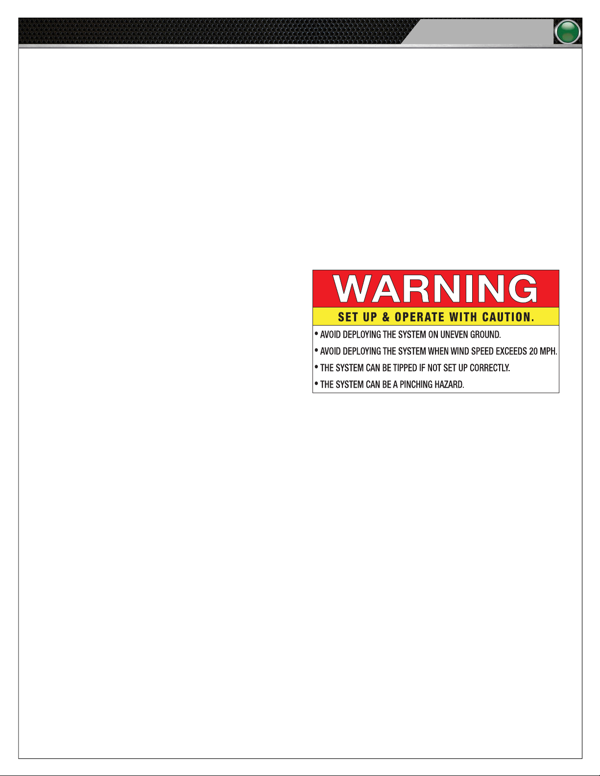
CAUTION: Deploy your Tempo Go system on even ground and beware of potential tipping hazards. Avoid deploying
the system when wind speed exceeds 20 mph. Failure to heed these recommendations may result in
system damage and personal injury.
Protecting Yourself and Those Around You
1. Allow only responsible individuals who have been
trained by a certied CoachComm technician to use
your Tempo Go system. Never allow people unfamiliar
with these rules and instructions to set up or operate
your system.
1
2. Do not stand, sit, climb, or ride on any part of Tempo
Go.
3. Do not operate the Tempo Go system in winds
exceeding 20 mph. System damage or personal injury
may occur. System damage due to wind is not covered
under the product warranty.
Figure 1: Tempo Go Safety Label
Electrical Safety
1. Do not submerge any part of the Tempo Go system in water.
2. Protect the power cords from being walked on or pinched, particularly at plugs, convenience receptacles, and the point
they exit from the apparatus.
3. Do not block any of the ventilation openings.
4. Do not install near any heat sources such as radiators, heat registers, stoves, or other apparatuses (including ampliers)
that produce heat.
5. Do not defeat the safety purpose of the grounding-type plug. A grounding-type plug has two blades and a third grounding
prong. The third prong is provided for your safety. When the provided plug does not t into your inlet, consult an electrician
for replacement of the obsolete outlet. Never break off the grounding prong.
6. Unplug the Tempo Go system during lightning storms or when unused for long periods of time.
7. Refer all servicing to qualied service personnel. Do not attempt to disassemble or open any panels. Doing so may expose
electrical parts and may also void the product warranty.
Page 6

2
Tempo Go
Safety Information
Mechanical Safety
1. Never, under any conditions, remove, bend, cut, t, weld, or otherwise alter standard parts of Tempo Go. Modications to
your system could cause personal injuries and property damage and will void your warranty.
2. The fan intakes and exhaust on the bottom and top of the Control Unit should be kept clear to allow for proper ventilation.
Do not cover the Control Unit while in operation.
3. Only use attachments/accessories/cables/hardware provided by the manufacturer.
4. Do not use blocks to increase height of system.
Noise Level Safety
Exposure to extremely high noise levels may cause a permanent hearing loss. Individuals vary considerably in susceptibility to
noise-induced hearing loss, but nearly everyone will lose some hearing if exposed to sufciently intense noise for a sufcient time.
To ensure against potentially dangerous exposure to high sound pressure levels, it is recommended that all persons exposed to
equipment capable of producing high sound pressure levels, such as this amplication system, wear hearing protectors while this
system is in operation.
Page 7

What’s Included with the Tempo Go System?
Tempo Go
What’s Included with the Tempo Go System?
CoachComm’s Tempo Go system is a state-of-the-art practice management system and helps a coach control practice by providing
time management, motivation, and coordination tools within one system.
The Tempo Go family of products includes the followoing:
• Tempo Control Unit and Tempo Remote
• Tempo Software
• Speaker Units
• Tripods
• Control Unit Mounting Bracket
• Hard Case for Tempo Control
• Weather Covers for Speakers
• Wired Microphone
• Audio Cables
3
Optional components provided by CoachComm include
• Practice Segment Timer(s)
• 25/40 Clock(s)
• Tempest
• Commando-T Remote
Each hardware component of the Tempo Go system is outlined in the following product overviews, and their operation is detailed in
full in later sections of this manual.
®
FX System
Page 8
4
Tempo Go
What’s Included with the Tempo Go System?
System Overview
The Tempo Control Unit houses the Tempo Software and functions to feed audio out to the system. With Tempo Software, you can
create and load a practice script to include songs, sound effects, and voice commands. The software syncs this script with the on
board practice segment timer and optional 25/40 clock(s) to drive the pace of practice. Controls at the Tempo Control Unit (or
optional Tempest FX wireless communication system) allow you to jump to the next period, adjust volume levels, add or subtract
times from periods, and play selected song and/or sound les. With Tempest FX, users can control the Tempo Software from
anywhere on the eld, communicate with other coaches wearing BeltPacks, and use the Voice Announce feature to engage players.
Valuable product features include the following:
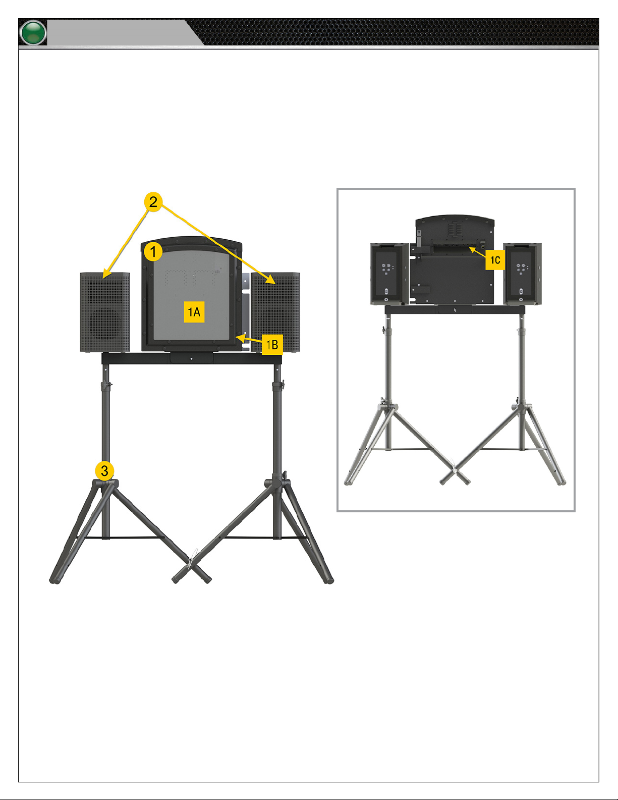
Figure 3: Tempo Go Rear
Figure 2: Tempo Go Front
1. Control Unit
A. Practice Segment Timer and Clock Interface
B. Volume Switch
C. I/O Panel (See page 8 for more information.)
2. Speakers (See page 8 for more information.)
3. Tripod and Bracket Mounting System (See page 6 for more information.)
4. Audio Cables (not pictured)
5. Power Cables (not pictured)
Page 9
What’s Included with the Tempo Go System?
Tempo Go
Tempo Clocks Overview
Two different clocks (sold separately) can be combined with the Tempo Go system. Practice Segment Timers and 25/40 Clocks can
be included as part of the practice script and reset using Tempo’s controls. As determined by the Tempo practice script, the Practice
Segment Timers display a period time countdown, and the 25/40 Clocks display a countdown as intervals. Both of these clocks are
wireless, portable, and battery operated (with additional solar panel charging.) AC power options are available in some instances.
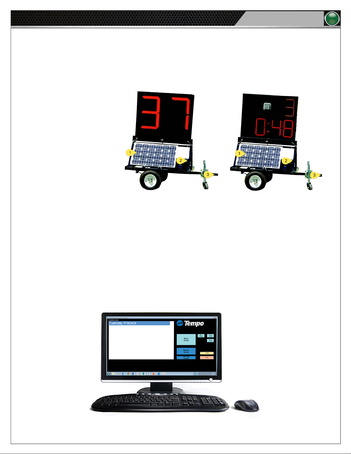
1. Solar Panel: Charges the
battery
2. Battery: Powers the Clock
3. Tow Hitch: Allows transport
of the Clock
5
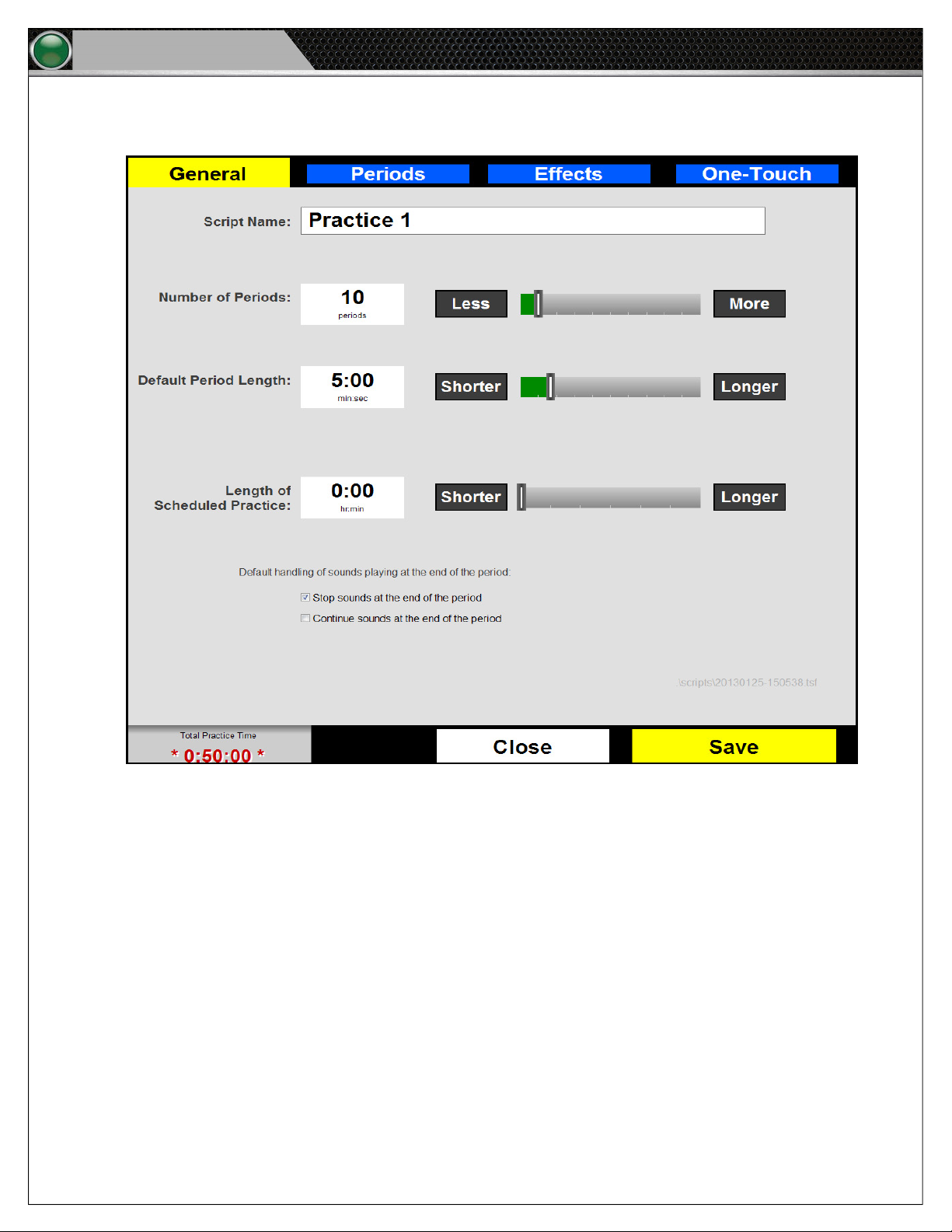
Figure 4: The 25/40 Clock (left) displays a countdown as intervals, and the Practice Segment Clock (right) displays a
period time countdown.
Tempo Software Overview
The Tempo Software is engineered to provide simple control over event scripting, including the following features:
• Organized audio for practice management
• Built-in coordination with Tempo Clocks
• PC (and optional Tempest FX BeltPack and Commando-T Remote) audio controls
• Sound effects
• Hot buttons and custom content grouping
Figure 5: Screenshot of Tempo Software.
Page 10
6
Tempo Go
Setup and Teardown Procedures
Setup and Teardown Procedures
The following is a step-by-step process to set up and tear down the Tempo Go Control Unit and tripods. The diagrams show the
use of two tripods (plus the Control Unit), but these procedures can be followed to incorporate the use of more to meet your
needs. Included is a legend to identify the images used throughout these steps.
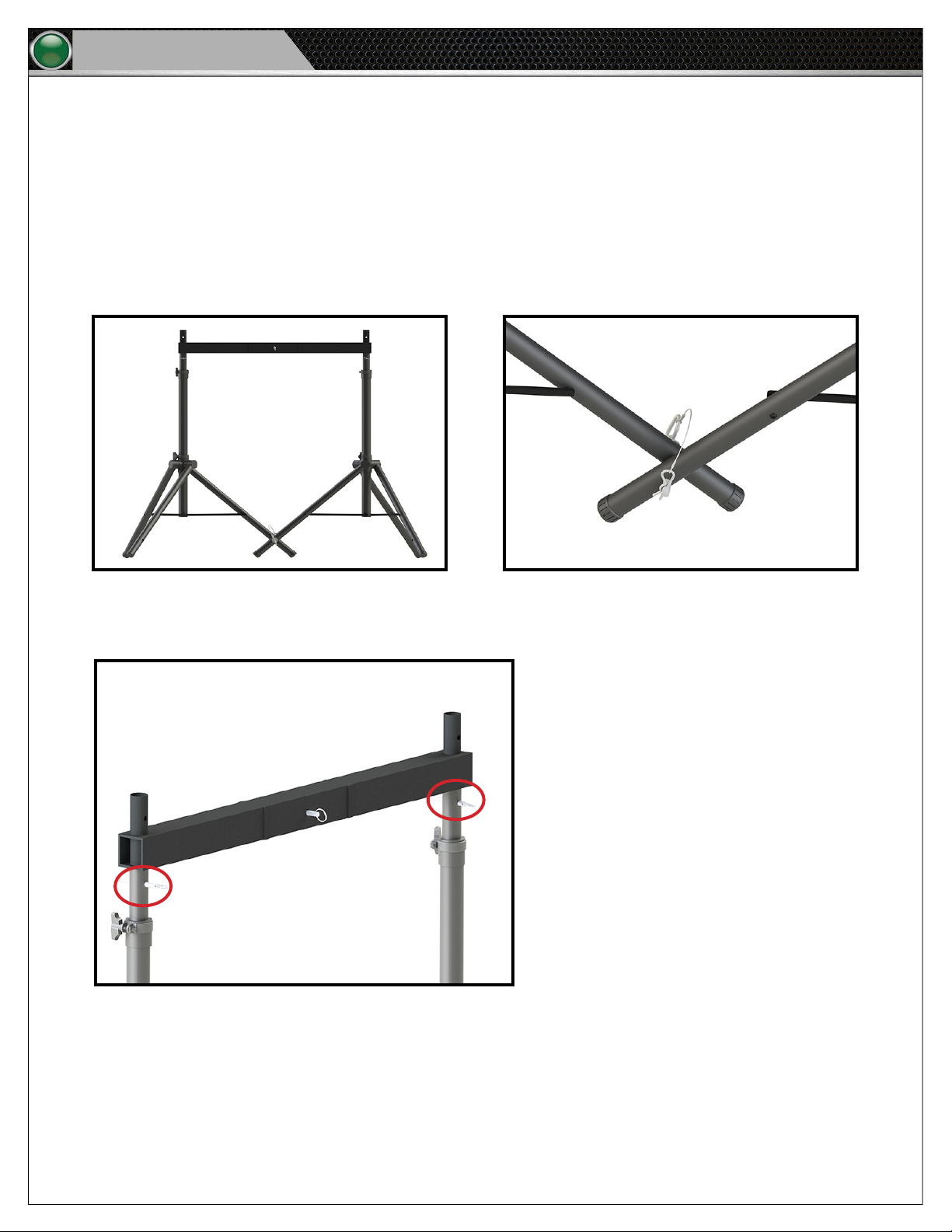
1. Fully extend the two tripods. (Full extension is when the sliding plastic collar contacts the bolt near the bottom of the
center tube.) Then, place the tripods side by side, aligning the holes in each tripod’s Leg 1. Secure with the provided
pin as shown in Figure 7.
Leg 1
Figure 6: Leg 1 of Each Tripod
2. Insert the mounting bracket’s two posts into the tops of the tripods. Use two of the provided pins to secure the posts in
place as shown in Figure 8.
Leg 1
Figure 7: Pinned Tripod Legs
Figure 8: Mounting Bracket Secured to Tripods
Page 11

Setup and Teardown Procedures
Tempo Go
3. Place the Tempo Control Unit onto the mounting bracket. Be sure to align the holes in the Control Unit mount and
bracket. Use one of the provided pins to secure it in place as shown in Figure 9.
4. Place the two speakers atop the bracket posts on each side of the Control Unit as shown in Figure 10.
7
Figure 9: Control Unit Secured to Mounting Bracket
Figure 10: Speakers Placed Atop Mounting Bracket
5. Connect the 6-pin ends of the two audio cables to the “LEFT” and “RIGHT” ports on the rear of the Control Unit. Then,
connect the 3-pin ends to the “MIC/LINE IN A” ports on the rear of each speaker. (The audio cables are yellow in Figure
11.)
6. Verify that the speakers’ settings are as
follows:
• LF: DEEP
• HF: FLAT
• Front LED: PWR
• Mic/Line in A: LINE
• Gain A: 0 dB
• Gain B: 0 dB
Note: See page 10 for information
about connecting an optional
®
Tempest
FX system.
Figure 11: Tempo Go Audio Cables (Yellow) and Power Cables (Red)
7. Connect the Control Unit’s power cable and the two speakers’ power cables into a power strip. (The power cables
are red in Figure 11). Then, connect the power strip (via extension cord if necessary) to a 120 Volt 15 Amp power
source.
Note: If you are using an optional Tempest FX system with Tempo Go, CoachComm recommends that you
power on your FX system before powering on your Tempo Go Control Unit and speakers. See page
®
10 for information about connecting an optional Tempest
FX system.
CAUTION: Protect the power cords from foot or vehicle trafc. Do not allow Tempo Go cords to become
pinched or crimped, particularly where plugs enter power receptacles and/or where they exit from the unit.
8. After your event, do the following:
• Turn off each Tempo Go product. To properly turn off the Tempo Control Unit, the user should hold down the
top four (4) buttons simultaneously until the clock display LEDs turn off. At this point, the power cable can be
disconnected from the Tempo Control.
• Disconnect all audio devices.
• Disconnect and secure audio and power cables.
• Disassemble the Control Unit, speakers, bracket, and tripods, and place them in their case and bags.
Page 12
8
Tempo Go
Hardware Installation
Hardware Installation
This section outlines how to connect and power your Tempo Go system.
Caution: When connecting, all volume controls should be turned down to prevent possible equipment damage;
then, adjust to the desired level after the inputs/outputs are connected.
Tempo Control Unit I/O Connection Panel
This section outlines the I/O connection panel to utilize your Tempo Go Control Unit.
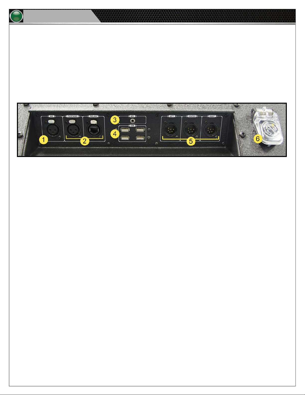
Figure 12: Control Unit I/O Connection Panel
1. Mic: Microphone-level input (female)
2. Tempest FX (Stage): FX audio input from Tempest FX Voice Announce output (female)
Tempest FX LAN: FX network Ethernet connection
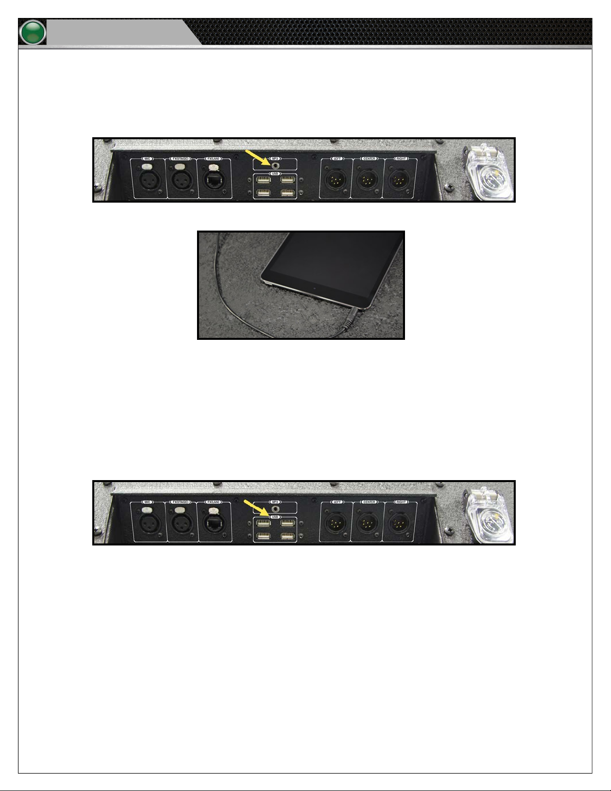
3. MP3 Player Port: Connection for 1/8 in. auxiliary cable
4. USB Ports: Used to connect the Tempo Remote and USB ash drives (to load the Tempo script).
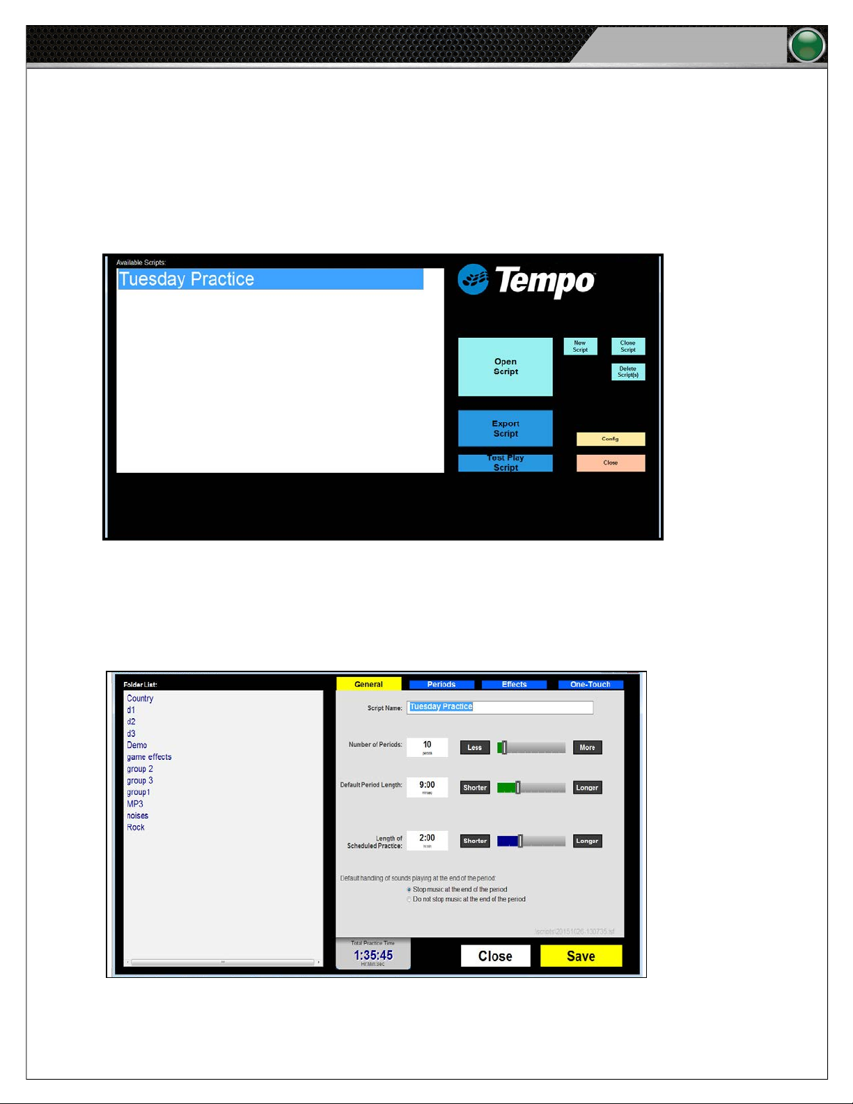
5. Output to speaker units (Left, Center, Right): Audio 6-pin connections to speaker units (male)
6. Power Connection: Power input for the Control Unit
Page 13
Hardware Installation
Speakers I/O Connection Panel
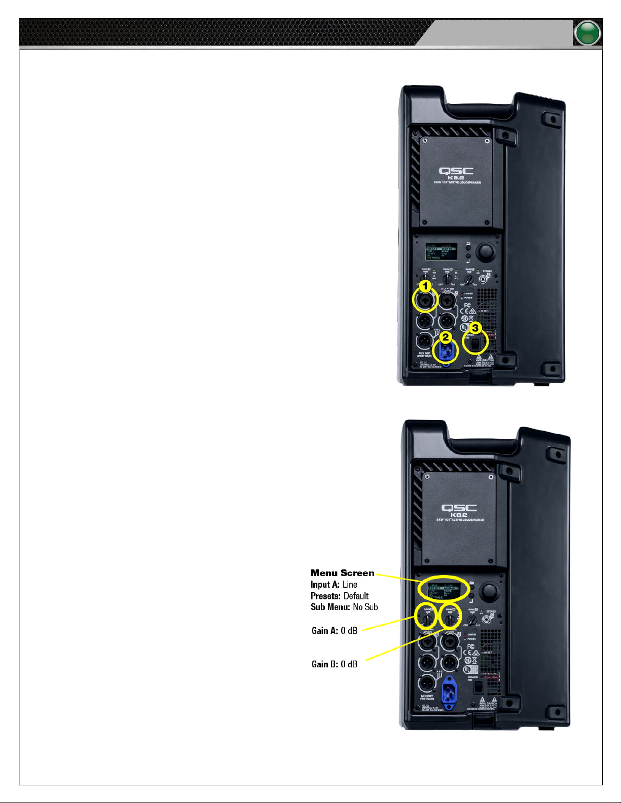
This section outlines the I/O connection panel needed to utilize your Speaker(s).
1. Audio Cable Connection
2. Power Cable Connection
3. Power Switch
Tempo Go
9
Speaker Settings
The Tempo Go speakers have have the following settings
applied from the factory. The Gain settings should be veried on
the rear of each speaker prior to each use.
Figure 13: Speaker Rear Detail
Figure 14: Speaker Settings Locations
Page 14
10
Tempo Go
Hardware Installation
Tempest® FX Installation (if applicable)
You must have the most recent Tempest rmware before using Tempest FX with your Tempo Go system. A CoachComm technician
will assist in upgrading your existing Tempest FX system if needed.
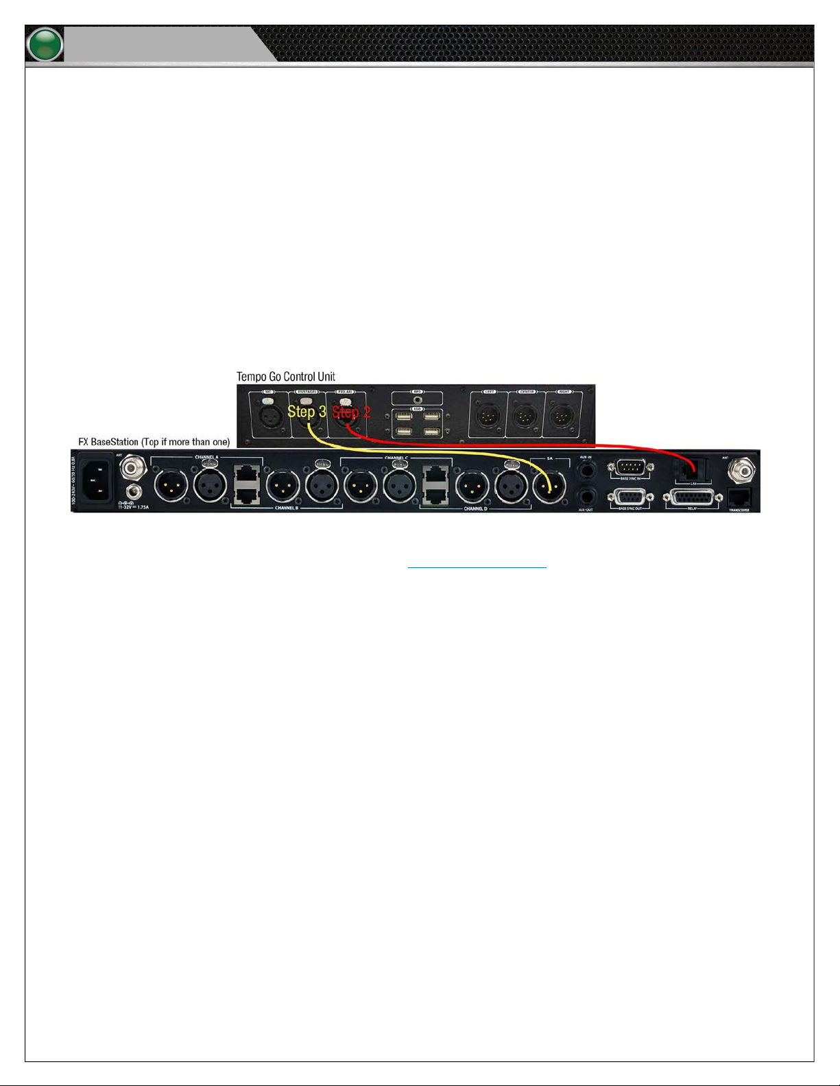
To connect the Tempest FX BaseStation to Tempo Go, do the following:
1. Place your Tempest FX BaseStation unit on a secure at surface on the sideline.
Note: If you have a dual FX system, always connect the top BaseStation to Tempo Go.
2. Connect a LAN network cable between the BaseStation and Tempo Go Control Unit. (See the red labels in Figure 15
below.)
3. Connect a Stage Announce XLR cable between the BaseStation and Tempo Go Control Unit. (See the yellow labels in Figure
15 below.)
Figure 15: Tempest FX BaseStation Cables to Tempo Go Control Unit
4. Follow the Tempest FX setup instructions found in the Tempest FX User Manual to connect and mount your Remote
Transceiver and to connect power. It is recommended that you power on your FX system before powering on your Tempo
Go Control Unit and speakers.
5. Test your FX system’s connectivity via the Commando-T remote to verify that it is controlling Tempo Go (for example, press
a one-touch sound button). See page 23 of this manual for additional information about testing connectivity.
Page 15
Hardware Operation
Tempo Go
Hardware Operation
Tempo Control Unit
The Tempo Control Unit controls all audio outputs to speaker units connected as part of the Tempo Go system. An overview of
the Control Unit’s hardware is provided in Figure 12 on page 8
following pages.
Connections and Controls
Audio Sources
Tempo Software: The Tempo Software is the user interface and main audio source for the Tempo Go system. Its installation and
operation is detailed beginning on page 14 of this manual.
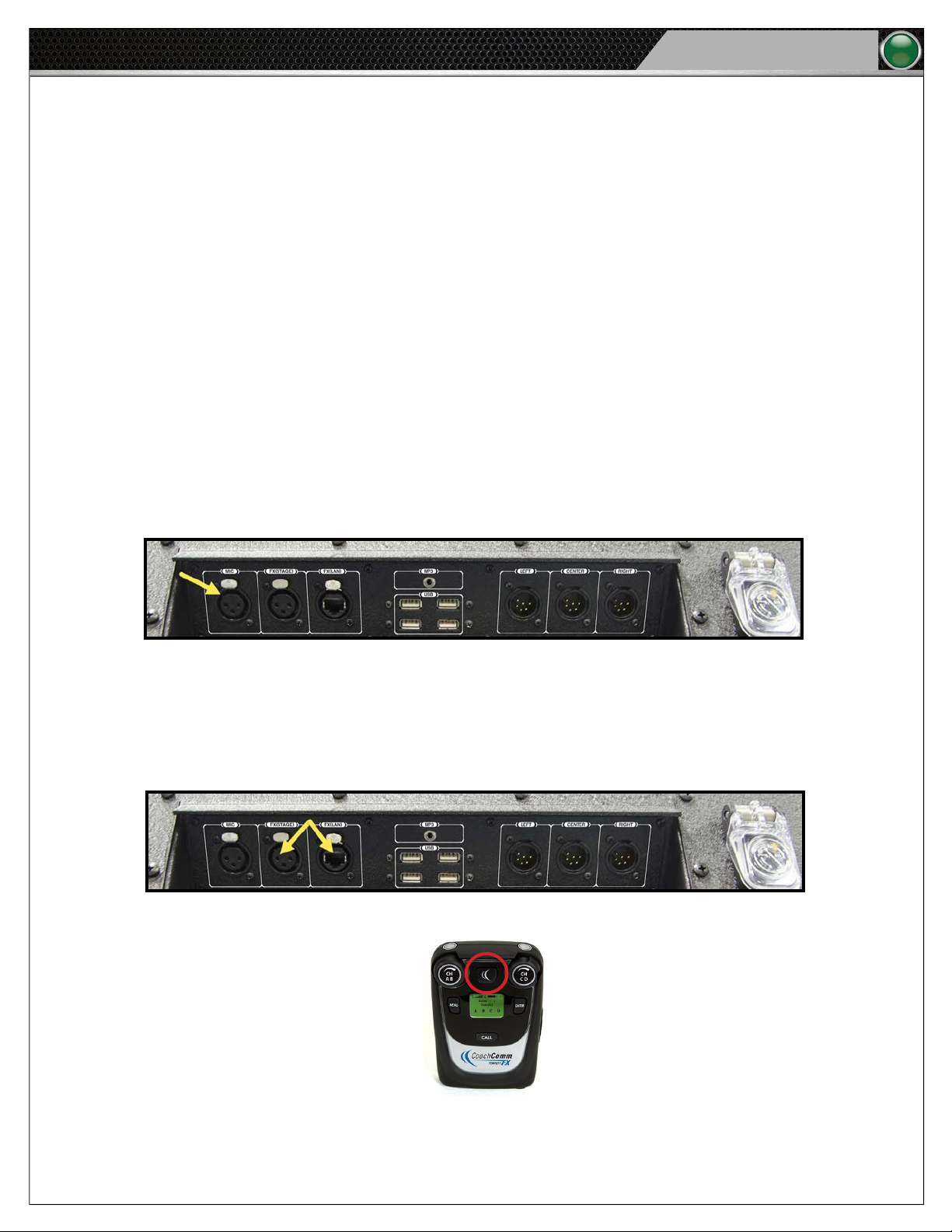
Mic: To operate a microphone, plug its 3-pin XLR connector into the Mic input on the I/O connection panel. Then, adjust the volume
with the Tempo Remote or Volume switch. The Tempo Go system has no phantom power; therefore, always use a dynamic
microphone.
, and operation of this product is detailed in procedures on the
11
Figure 16: Tempo Go’s Control Unit connections for a microphone
Tempest FX (if applicable): The Voice Announce feature broadcasts one’s voice through the entire Tempo Go system using your
connected Tempest FX system. To operate this feature, open the Tempo Software and connect a headset to the appropriate BeltPack.
Hold down the STAGE button (see Figure 18) on the BeltPack through the entirety of speaking. See page 10 for information about
connecting an optional Tempest
Figure 17: Tempo Go’s Control Unit connections for a Tempest FX BaseStation
®
FX system to Tempo Go.
→
Figure 18: Sample Stage Button on BeltPack
Page 16
12
Tempo Go
MP3: To operate an MP3 audio source, connect the desired input device to the provided 1/8 inch mini (male) auxiliary cable, and
then to the Control Unit’s I/O panel. Adjust the volume using the Tempo Remote or Volume switch. The quality of your listening
experience is directly inuenced by the quality of your audio content from your MP3 device. Therefore, to minimize variations or
distortion of audio content, it is recommended to only use the highest quality licensed content obtained from reputable, licensed
download providers.
Figure 19: Tempo Control Unit MP3 Port
Hardware Operation
Figure 20: Connect an audio MP3 source using an Auxiliary Cable.
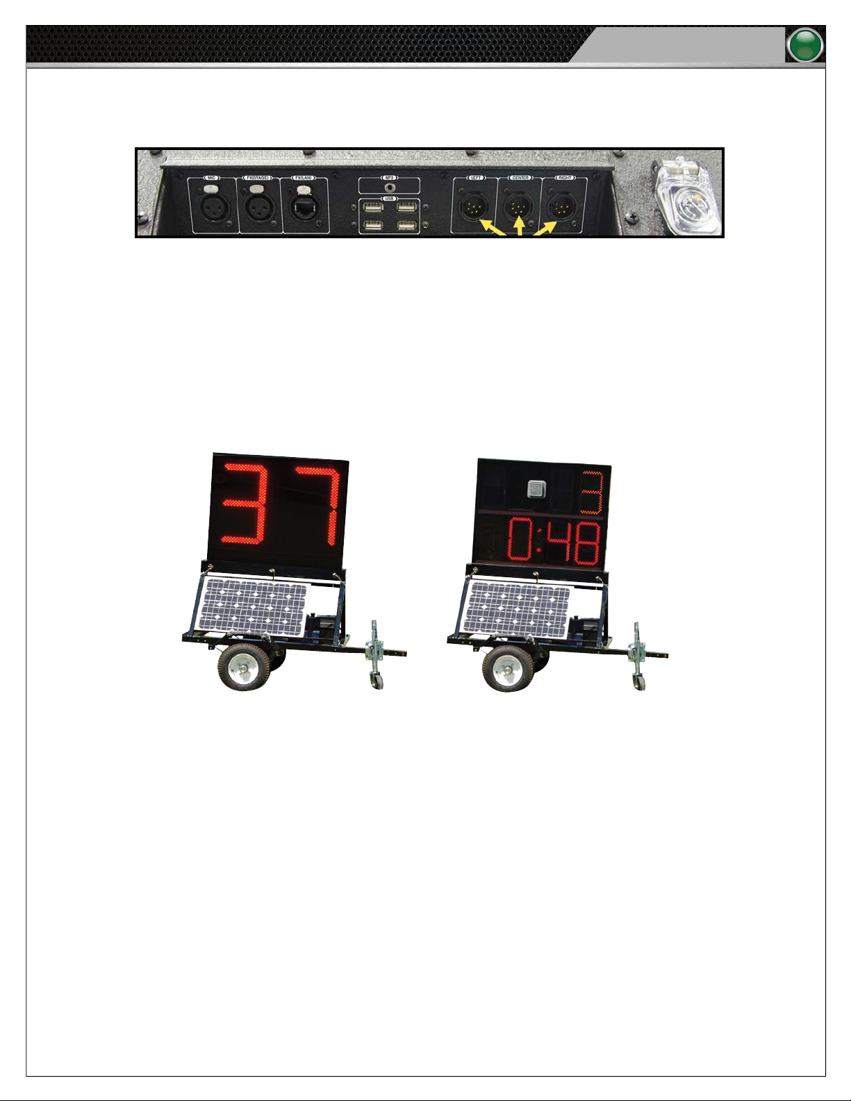
USB Ports: To connect a USB ash drive or Tempo Remote to the unit, use one of the four provided USB ports on the Control Unit’s
IO connection panel.
You can use these ports to connect the following:
• USB ash drive containing the exported Tempo practice script
• Tempo Remote (See page 24 of this manual for more information.)
Figure 21: Tempo Control Unit USB Ports
Page 17
Hardware Operation
Audio Out: To send audio output to speakers, use the Output to speaker connections on the Tempo Control Unit’s I/O
connection panel.
Figure 22: I/O Connection Panel Output to Speaker Connection
Tempo Go
13
Time Clocks
The clocks are available in two models: battery-powered or AC-powered. Plug the clock(s) into the battery on the clock trailer or into
an AC power source for operation. Once powered, they can be controlled wirelessly via the Tempo script. For battery-powered clocks,
it is best to charge the clocks overnight or when not in use.
Figure 23: The 25/40 Clock (left) displays a countdown as intervals, and the Practice Segment Clock (right) displays a period time countdown.
Page 18

14
Tempo Go
Software Installation and Operation
Software Installation and Operation
The following section details procedures for operating Tempo Software.
Installation
Tempo Software is already provided on the Tempo Go system’s Tempo Control Unit. To install Tempo Software on a secondary PC,
contact CoachComm for assistance.
Minimum Software Requirements
The minimum software requirements for running Tempo Software on a secondary PC are listed below:
• Processor: 1GHz
• RAM: 512 MB
• Disk Space: 100 MB
• Windows XP or Windows 7 SP1
Operation
Organize Your Audio Library
Organize your MP3 audio les within your computer’s directory so they can be easily imported into a Tempo script. Do this by placing
the les you’d like to use in your Tempo audio library. To access your Tempo audio library, use these steps:
1. Click on Start.
2. Go to My Computer and open your (C:\) folder.
3. Open the Tempo Go folder, and then open the folder labeled “library”.
CoachComm recommends creating organized folders in your audio library to hold your music and sounds (e.g., crowd noise, game
sounds, announcer’s or coaches’ voice, etc.) to play in the Tempo Software.
Important: All music les must be .mp3 les to play in the software.
In order for new MP3’s to be visible in the Tempo Software, you will have to close the software and reopen any time you make
changes to the les in your audio library.
Page 19
Software Installation and Operation
Tempo Go
Open Tempo Software
Open the Tempo Software by double-clicking the Tempo shortcut on your computer’s desktop. If the desktop shortcut is accidentally
removed, you can access the software by going to your C:/Tempo Go folder and double clicking on the le labeled “runtempoTempo
Go desktop”.
Build a Script
1. To build a script from scratch, open the Tempo Software and click on New Script.
15
Figure 24: Home Screen New Script Menu Option
The new, blank script will display with these tabs: General, Periods, Effects, and One-Touch. The Folder List shown on the
left hand side of the screen displays all of the music folders you created in your Tempo audio library.
Note: You can preview an audio le in this list by selecting it and using the Play/Pause button at the bottom of the
screen. Changing your song selection will automatically start the next song until you click Pause.
Figure 25: Tempo Software Edit Screen
Page 20
16
Tempo Go
General Tab
2. Enter your general script settings on the General tab. Click Save when done.
Software Installation and Operation
Figure 26: Tempo Software General Tab
A. Name your script.
B. Select your total number of practice periods (i.e., sections of practice).
C. Determine your default period length. (This is your most used period length. You can customize length by period in
the Periods tab)
D. Determine your total scheduled length of practice.
E. Determine whether or not the music stops at the end of the period.
Note: If you make your total practice time longer than your allowed or allotted practice time, the timing mechanism
will ash red on the bottom center of the screen. This control functions to monitor practice-time regulations.
Page 21
Software Installation and Operation
Periods Tab
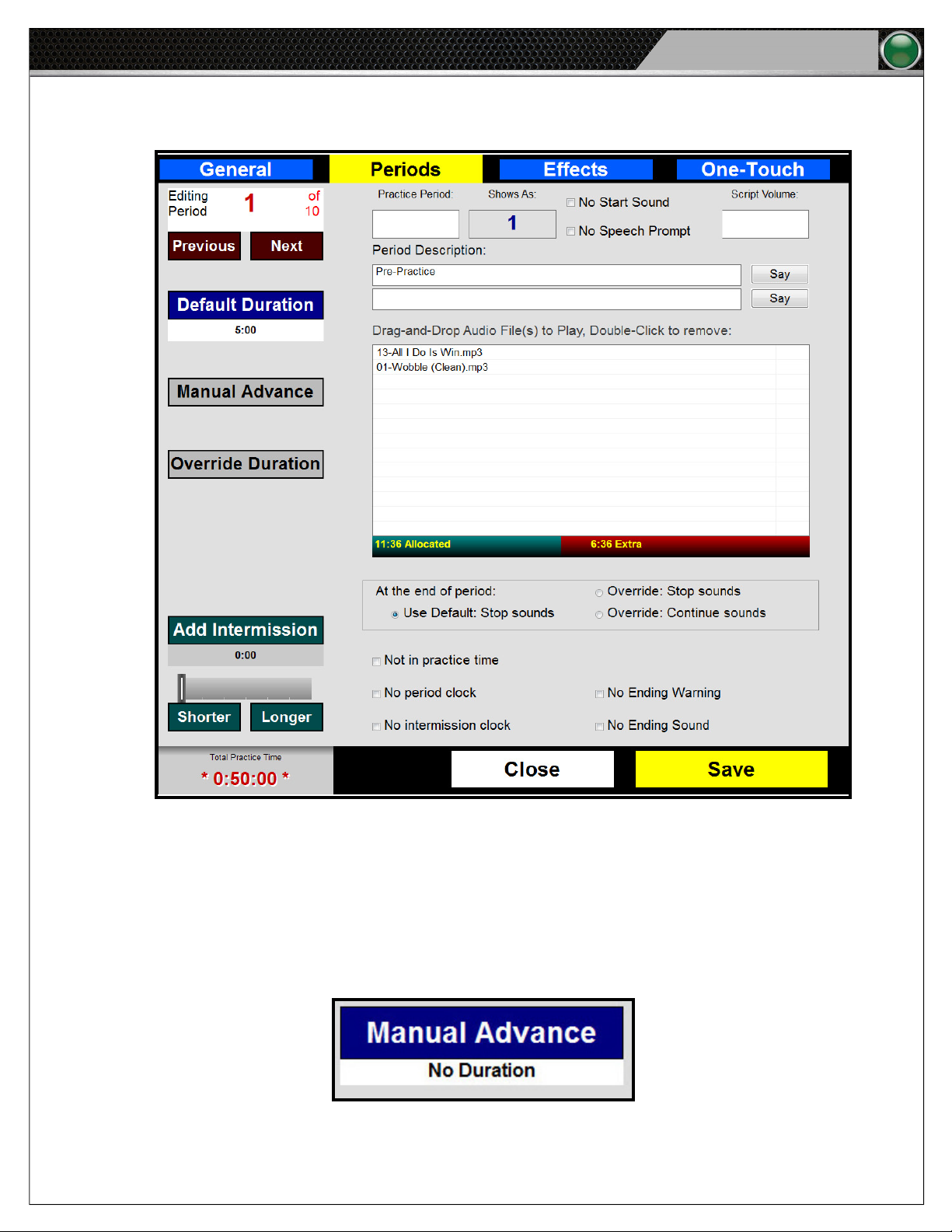
3. Enter the settings for each Period on the Periods tab. Click Save when done.
Tempo Go
17
Figure 27: Tempo Software Periods Tab
A. Editing Period: The top left corner of the tab displays the number of the period you’re editing. Use the Previous and
Next buttons to navigate to each period.
B. Default Duration: Setting for all periods on the General tab and is shown on the Periods tab.
C. Manual Advance: Select if you prefer your period to have no time associated with it. With this setting, a period will
not advance to the next period unless you manually do so from the Tempo Remote, Tempest FX BeltPack, or
Commando-T Remote. This setting’s options are hidden until it is selected.
Figure 28: Manual Advance Option. Select if you do not
want the period to have a time frame. This setting’s
options are hidden until it is clicked.
Page 22
18
Tempo Go
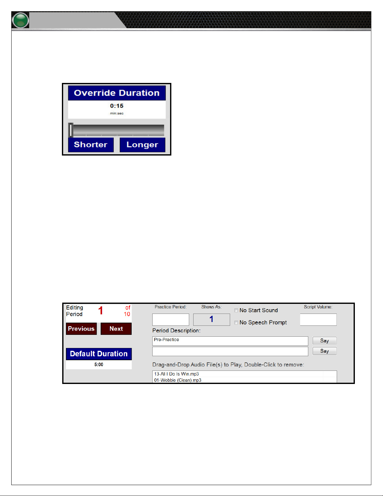
D. Override Duration: Select if you need to adjust the duration of a specic period to be shorter or longer than the
Default Duration. For example, if the majority of your periods are ve minutes each, but you want a specic period to
be eight minutes long, you can override just that period’s duration using this feature’s slider or Shorter and Longer
buttons. This setting’s options are hidden until it is selected.
Software Installation and Operation
Figure 29: Optional Override Duration Option. This setting’s
E. Add Intermission: Set an optional period Intermission using the slider or Shorter and Longer buttons. Intermission
is time that will not count toward practice that will occur after a period.
F. Practice Period: Determine what (if any) period number will display on your period clock (if applicable). If you leave
the Practice Period eld empty, the clock will always display the default period number. The Shows As eld displays
what will be seen in the software and on the clocks as you run the script.
• Type two hyphens (--) in this eld to remove the period number from the period clock. The period time will still be
• A zero can be placed in this eld to display a zero on the period number.
G. Tempo’s Start Sound plays the sound you set to begin a period. Selecting the No Start Sound check box turns off this
feature.
H. Tempo’s Speech Prompt reads aloud each period’s title and description as the period begins. Selecting the No
Speech Prompt radio button turns off this feature.
options are hidden until it is clicked.
displayed on the clocks.
Figure 30: Use the Practice Period Number eld to determine what period number will display on your period clock.
Page 23
Software Installation and Operation
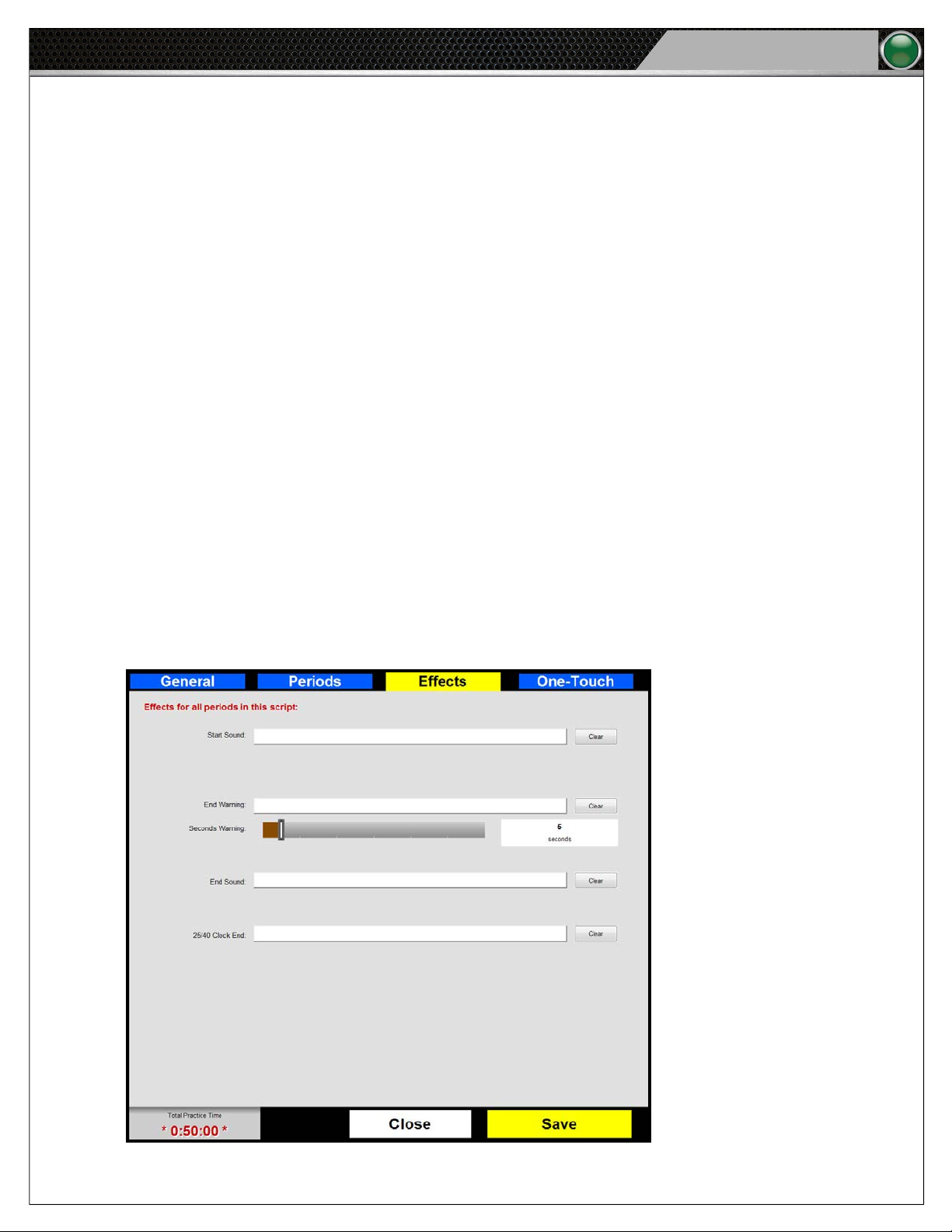
I. In the Script Volume eld, you can put a number between 1-100 to set the volume level for that period as a
percentage of total master volume level.
J. Text written in the Period Description eld will be said aloud at the beginning of the period if the Text to Speech
Prompt is enabled.
K. The Audio Files area of the window holds all of your audio les to play during the period. To add a le, drag and drop
it to the period’s Audio Files area from the Folder List. The period’s Allocated and Extra time is displayed below this
panel. Allocated time is calculated by adding the total amount of time of your audio clips. It is best practice to add
more than enough audio les to completely ll each period in case a user skips a song mid-series. Double-click on
an added audio le to remove it from the list.
L. The default duration is set in the general tab to stop sounds or continue sounds at the end of each period in the
script. In Default Duration box, you can override the script setting for an individual period.
M. Additional options for the Periods tab are shown below.
i. Not in Practice Time: Check this box to remove the period from the total practice time. Typically used for
practice beginning or stretching time.
ii. No Period Clock: Check this box to remove the period time from the period clock. The period number will still
be displayed on the clocks.
Tempo Go
19
iii. No Intermission Clock: Check this box to remove the intermission information from the period clock.
iv. No Ending Warning: Check this box if you do not want to have an ending warning for the period.
v. No Ending Sound: Check this box if you do not want to have an ending sound for the period.
Effects Tab
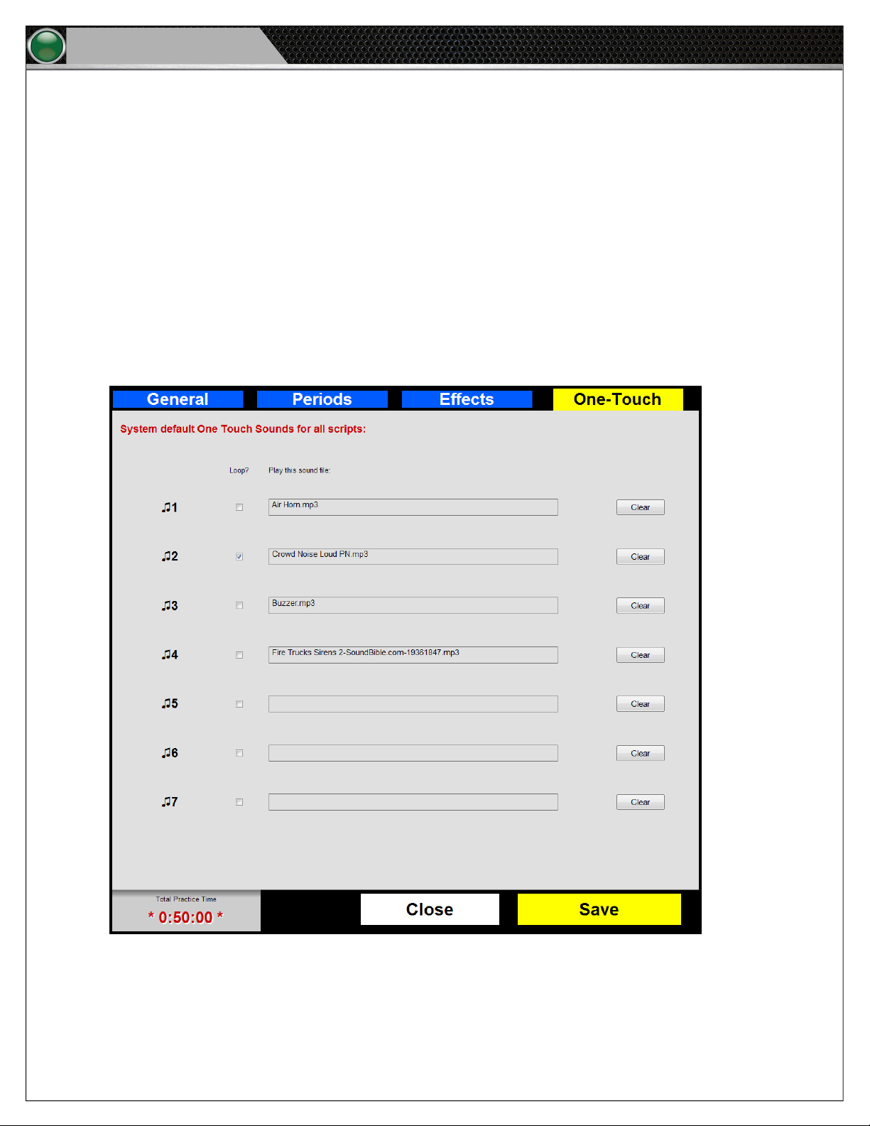
4. Determine the sound effects for all periods on the Effects tab by dragging the selected audio le from the Folder List to the
applicable eld. Delete unwanted audio les using the Clear button. Click Save when done.
Figure 31: Tempo Software Effects Tab
Page 24
20
Tempo Go
A. Start Sound: Effect for the start of the period
B. End Warning: Effect for the period End Warning
C. Seconds Warning: Sets the time remaining in the period when the End Warning sounds
D. End Sound: Effect for the end of the period
E. 25/40 Clock End: Effect for the end of the 25/40 clock countdown
One-Touch Tab
5. Set specic one-touch buttons for the Tempo Remote using the One-Touch tab by dragging the selected audio le from the
Folder List to the applicable eld. Delete unwanted audio les by selecting Clear. Click Save when done.
Software Installation and Operation
Note: Including both a start sound and end sound will play a sound both at the end of the period and at
the beginning of the next (as if the sound repeats back-to-back). Most users choose to have one or
the other, not both.
Figure 32: Tempo Software One-Touch Tab
A. Assign each audio le a Label to correspond to the Tempo Remote.
B. To set a le to continuously play, check its Loop box.
C. Verify all buttons by clicking Save, closing the script editor, and test playing the script. Each one-touch button should
function with the on-screen Tempo Remote.
Page 25
Software Installation and Operation
Tempo Go
Test a Script
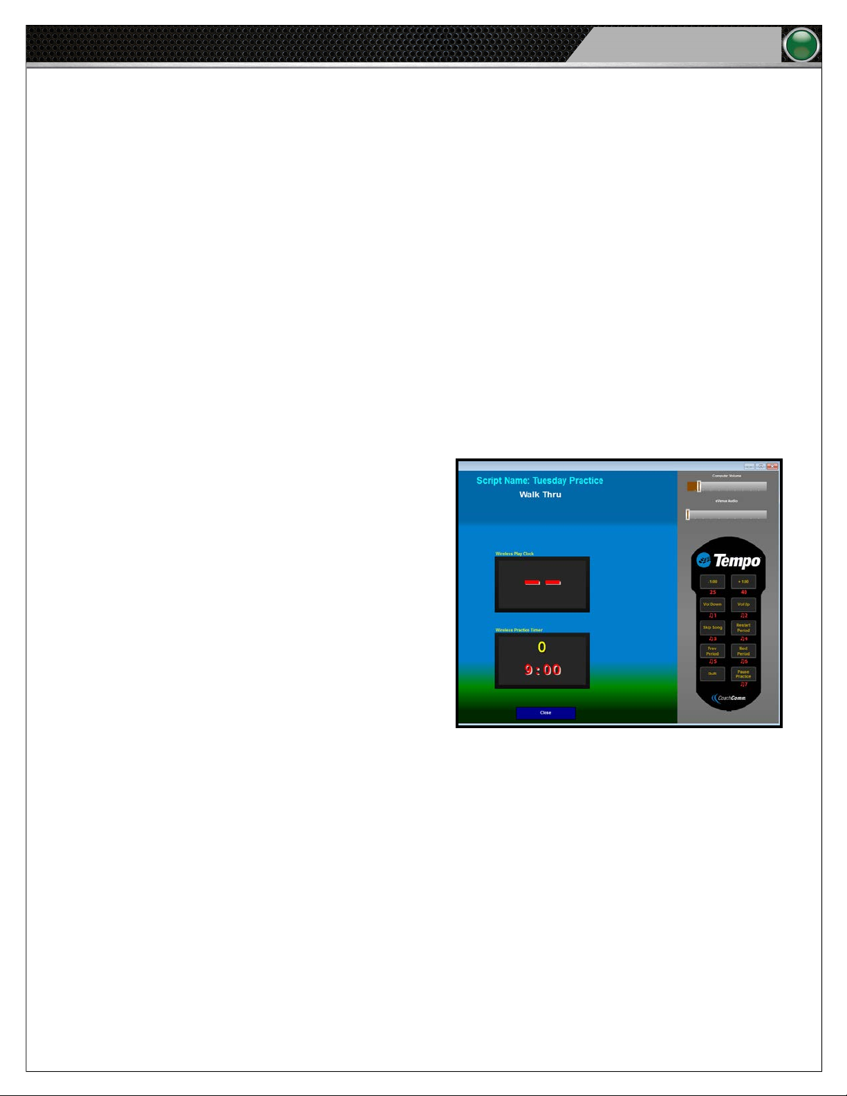
To play back a saved script and test how it will appear on your system, select it from the “Available Scripts” List on the Tempo Home
screen and click on Test Play Script.
The Test screen displays a model of your Control Unit and any connected wireless clocks as they appear during script playback.
Use the on-screen Tempo Remote to model the identical controls you will have on the eld. For more information on how this remote
functions, see “Tempo Remote” on page 24 of this manual.
Edit a Script
1. Select the script you wish to edit from the Tempo Home screen.
2. Click Open Script and make your desired changes. Click Save before closing.
Clone a Script
Cloning a script makes a duplicate copy of the selected script. This is useful in situations where you would want nearly identical
scripts for each practice day, but still need to change a few details. Cloning prevents you from having to create each script from
scratch.
21
1. Select the script you wish to clone from the Tempo Home
screen.
2. Click Clone Script. Conrm your decision in the pop-up
prompt. Your duplicate copy will display in the Available
Scripts list with an identical le name, plus the date and
time of cloning.
3. Select your new script, click Open Script, change the
title to whatever you want (e.g., Wednesday Practice),
and make your other desired changes. Click Save before
closing.
Delete a Script
1. Select the script you wish to delete from the Tempo Home
screen.
2. Click Delete Script(s). Conrm your decision in the pop-up
prompt.
3. To show synced changes, you must close the Tempo Software and reopen it.
Figure 33: Tempo Software Test Play Screen
Page 26
22
Tempo Go
Software Installation and Operation
Congure the System
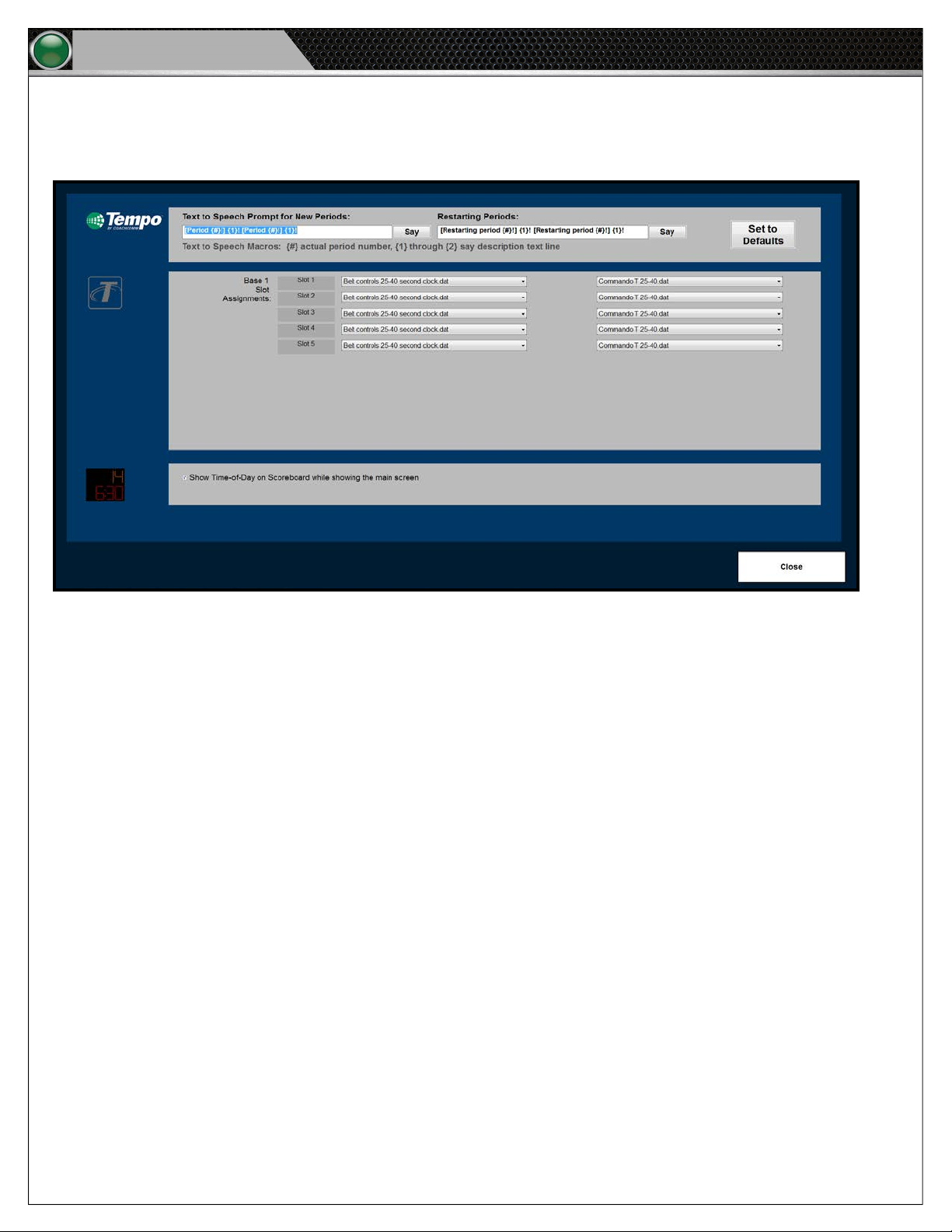
The Cong screen on the Tempo interface is used to control the functionality of your Tempest FX BeltPacks (if applicable), to
determine a clock feature, and also to congure your text-to-speech prompts to work for all periods within your script.
Figure 34: Tempo Software Conguration Screen
• The Text-to-Speech Prompt for New Periods and Restarting Periods: Populates elds automatically for you by clicking
Set to Default Value. Currently, the default value will have the PC read the period number and description line twice. You
can choose to leave it like that, delete one of the segments, or delete the line all together if you don’t want anything read
before the periods of your script. Customize this to whatever your coach likes best. You can click on the Default button at
any time to return to default settings.
• BeltStation Controls: Congure the control functions for all associated Tempest BeltPacks.
• Commando-T Controls: Congure the settings of a Commando-T Remote associated to a BeltPack. Select either Volume
Remote, Clock Remote, or No Remote.
• Time of Day: Select this check box to display the time of day on your clocks when the Tempo Software is on the home
screen. When checked, the period clocks will display the time of day when the Tempo Software is on the Home screen.
When not checked, the period clocks will display nothing when the Tempo Software is on the Home screen.
Page 27
Software Installation and Operation
Tempo Go
Export and Play Script
1. Plug your dedicated Tempo external USB drive into your PC.
2. Select your script from the “Available Scripts” List on the Tempo Home screen. Then, click on Export Script.
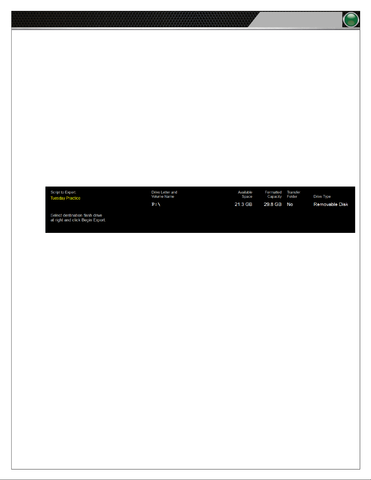
3. As seen in Figure 35 below, the Export screen will display several columns of information: The Script to Export and all
External Drives’ Letter Labels along with their Available Space, Formatted Capacity, Transfer Folder, and Drive Type.
4. Select your dedicated Tempo external drive from the list. The software will only allow you to export one script at a time,
and it will overwrite old scripts on your external drive to make sure this is the case.
5. Click the Begin Export button. Your script transfer will commence, and the screen will display Done when your export is
complete. Browse out to your ash drive and verify the Tempo Go folder is on the ash drive. We recommend you use the
same ash drive to export every time.
6. Turn the Control Unit on. After approximately 20 seconds, the clock will start a USB animation at which time you can plug
in your ash drive.
23
7. Start practice (after the software displays the script on the screen) by pressing the Pause Practice button on either the
Tempo Remote or Tempest
Figure 35: Tempo Software Export Screen
®
FX Commando-T controls.
Test FX Connectivity
After the script is loaded, you should verify your FX is connected and controlling Tempo.
1. Using your Commando-T Remote, press one of the one-touch sound buttons, or Pause Practice to start the script. If
the remote function works, then you are correctly connected to FX and can start practice when ready. If you do not have
control, (that is, your Commando-T Remote’s one-touch does not work), you should verify all connections are correct using
the sub-steps below.
A. Once you have veried connections, you should use the Tempo remote to turn off the PC, then turn off the speaker
unit.
B. Turn off the power to your speaker unit and wait 30 seconds.
C. Power the speaker unit back on and wait for the USB animation. Re-insert your ash drive and test Commando-T
Remote functionality again.
Page 28
24
Tempo Go
Software Installation and Operation
System Control
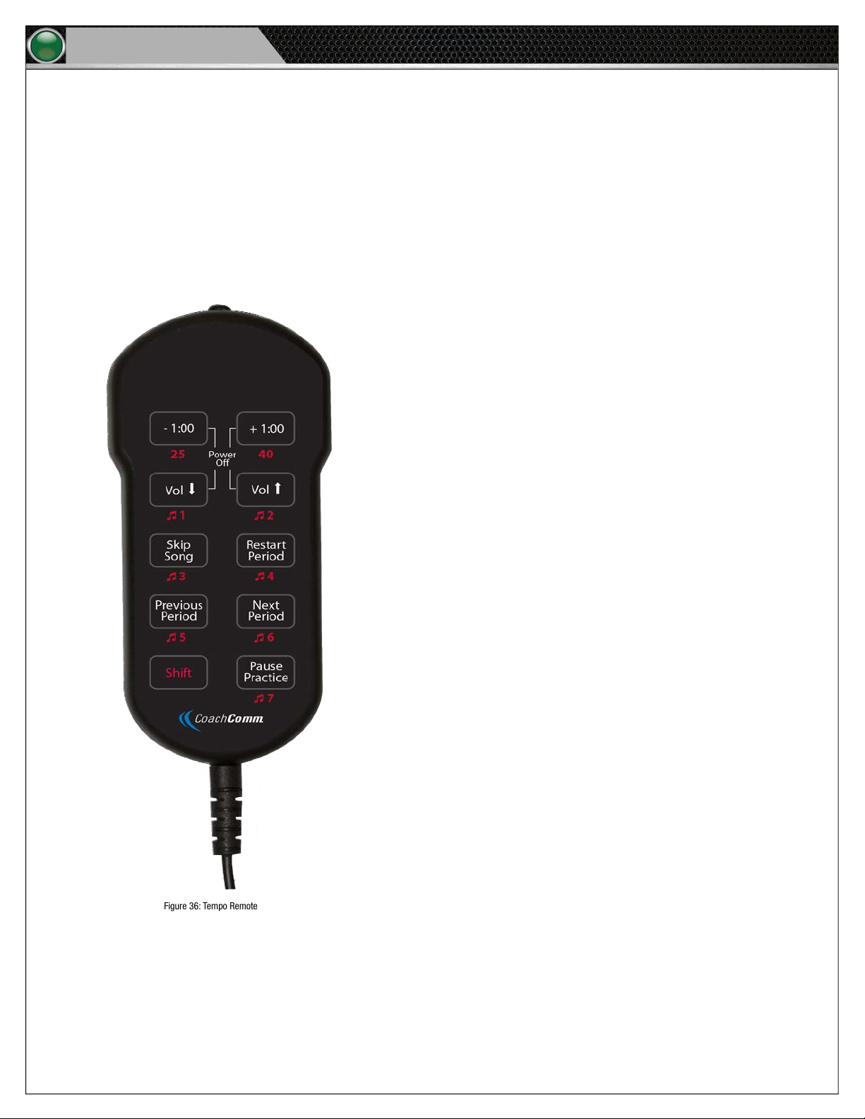
You can remotely control the Tempo Go system using the Tempo Remote, Tempest FX BeltPack, or BeltPack combined with a
Commando-T Remote.
Tempo Remote
You can control practice using the Tempo Remote, which plugs into any available USB port on the Control Unit.
• -1:00, +1.00: Subtracts or adds a minute to a
period.
Shift + 25: Starts 25 second clock.
Shift + 40: Starts 40 second clock.
• Volume
• Skip Song
• Restart Period:
• Previous Period: Returns to beginning of previous
• Next Period
• Shift:
• Pause Practice: Toggles between pause and start/
• Power Off
: Decreases or increases volume.
Shift + 1–7: Plays sound assigned to the selected
one-touch number.
: Forwards to next song.
Restarts current period.
period.
: Starts next period.
Changes remote functions when pressed and
used in combination with another button.
continue practice.
: Press and hold top four buttons to turn
off Control Unit.
Figure 36: Tempo Remote
Page 29
Software Installation and Operation
Tempo Go
25
BeltPack and Headset
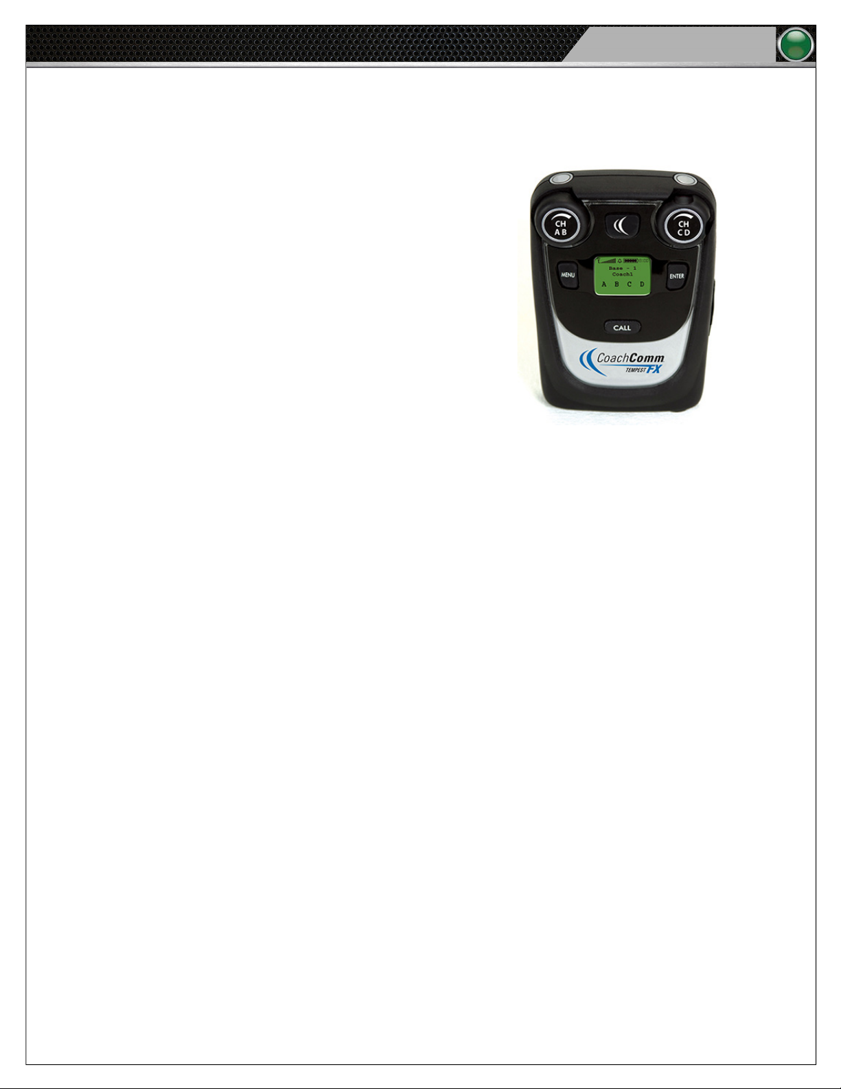
The Tempest FX system is an optional add-on to Tempo Go, and with it, you can communicate and control system functions
remotely through a BeltPack.
The default BeltPack remote commands available are:
• Turn CD Knob: Adjust Volume
• Call + Talk AB: Start 25-Second Clock
• Call + Talk CD: Start 40-Second Clock
• Call + Stage: Display Practice/Script Time Remaining
• Call + Hold Enter: Next Period
• Call + Hold Menu: Previous Period
• Call + Hold Menu: Restart Period
• Call + Hold Stage: Pause/Restart Practice
• Call + Turn AB Knob: Adjust Period Length
Voice Announce is also a feature that will duck the music while the designated coach speaks over the system. In this situation, the
music’s volume level is lowered, and the voice volume level is not. To do this, your headset should be plugged into a BeltPack that
has been congured in the Cong menu and that has Voice Announce enabled.
Figure 37: FX BeltPack
Page 30
26
Tempo Go
Software Installation and Operation
Commando-T Remote
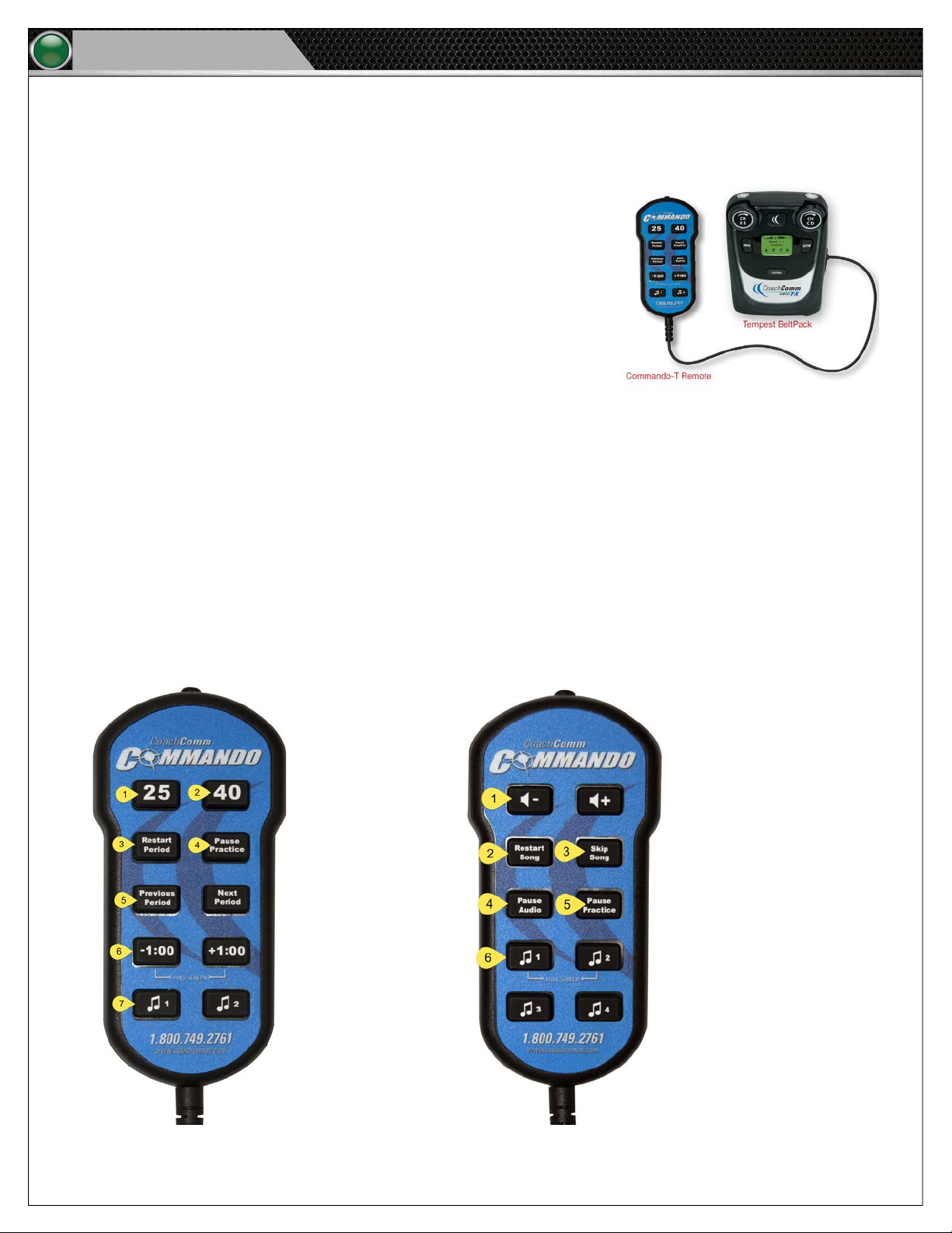
The Commando-T Remote is an optional controller to use with your existing Tempest FX BeltPack. Its simple controls perform the
same functions as the BeltPack alone, but with an easier interface.
Commando-T Clock Remote Functions: (See Figure 39)
1. 25: Starts the 25-Second Clock
2. 40: Starts the 40-Second Clock
3. Restart Period: Restarts the current period from the beginning
4. Pause Practice: Pauses clocks and script audio
5. Previous/Next Period: Moves to previous or next period in the script
6. -1:00 / +1:00: Adds or removes one minute from the period clock
7. One-Touch Buttons 1 and 2: Play the sounds associated to the rst and
second One-Touch buttons on the Tempo Play screen
Commando-T Volume Remote Functions: (See Figure 40)
1. Volume +/-: Changes script audio volume level
Figure 38: Commando-T Remote and FX BeltPack
2. Restart Song: Restarts the current song from the beginning
3. Skip Song: Skips current song in the script and plays the next
4. Pause Audio: Pauses script audio
5. Pause Practice: Pauses clocks and script audio
6. One-Touch Buttons 1–4: Play the sounds associated to the top four One-Touch buttons on the Tempo Play screen
Figure 39: Commando-T Clock Remote
Figure 40: Commando-T Volume Remote
Page 31

System Maintenance and Storage
Tempo Go
System Maintenance and Storage
1. If the system is exposed to rain, dry all parts of the Tempo Go System carefully, including cables and connectors.
2. Always make sure that nuts and bolts are secure prior to and after moving or operating.
3. Connect or disconnect cables by holding the connectors (not the sheath of the cable) and pressing the release button if
applicable.
4. It is recommended that the Tempo Go system be stored in a climate-controlled environment when not in use.
5. Storage Temperature: If a climate-controlled storage space is not available, Tempo Go equipment can be stored in
temperatures ranging from 5° to 130° F. However, when going from cold to warm environments, electronics can form
condensation, which can cause damage to the electronic components. If storing your system in these type of conditions,
wait for the equipment to acclimate to the ambient temperature before using.
Operating Temperature:
A. If using your Tempo Go system at or near freezing temperatures, it is recommended that you warm speakers up
gradually by playing at a low volume for at least 20 minutes before playing at loud levels.
B. You may notice performance issues when operating above the ambient temperature of 122° F.
27
6. Verify that system power is off and disconnected before storing the system.
Page 32
28
Tempo Go
External Connection Diagram
External Connection Diagram
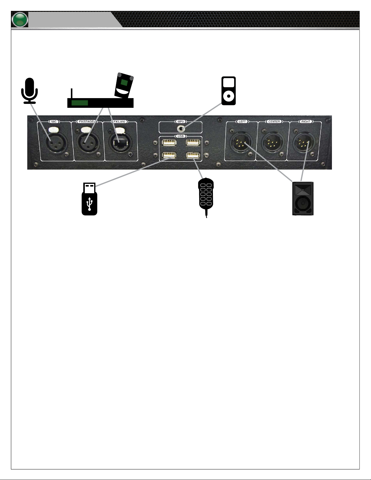
Figure 41 provides specic connection details for the Tempo Go Control Unit.
Mic
Control Unit Back Panel
External USB Drive with
Tempo Script (available
USB port)
Figure 41: Control Unit I/O Connection Panel Showing Possible Connected Devices
Tempest® FX
System
Portable
Music Player
Tempo USB
Remote
(available USB port)
Speakers
Page 33

System Specifications
Tempo Go
29
System Specifications
Control Unit
Depth: 6.625 in.
Width: 24 in.
Height : 16.5 in.
Weight: Approx. 45lb.
Power Requirements: 120V dedicated AC circuit for three-prong, 15 amp u-ground Edison plug. Only one
Tempo Master allowed per circuit.
Power Cable Length: 82”
Audio Cable Length: 45” (each)
Speakers
Power Requirements: Universal Power Supply 100-240 VAC, 50-60 Hz
Audio Coverage: Approximately 105°
Frequency Response: 66 Hz - 18 kHz / 59 Hz - 20 kHz (speakers/speakers.2)
Amp Protection: Thermal Limiting, Ouput Overcurrent, Overtemperature Muting
Amp Total Power Output: 1000 watts / 2000 watts (speakers/speakers.2)
Page 34
30
Tempo Go
Product Support and Warranty
Page 35
Product Support and Warranty
Tempo Go
31
Page 36
CoachComm, LLC
205 Technology Parkway
Auburn, Alabama 36830
1.800.749.2761
www.coachcomm.com
©2018 CoachComm LLC. All rights reserved. Tempo® is a registered trademarks of CoachComm LLC. The CoachComm logo is a registered trademark of
CoachComm LLC. Document Reference: 2018.07 D0000421_A
 Loading...