

Page 1

Operating Manual
Page 2

eVenue Thunder
Thank You
We at CoachComm® want to thank you for purchasing an eVenue Thunder™ system. We are committed to providing you with a
high-quality product that will deliver dynamic sound, distributed coverage, reliable mobility, and innovative operational features. In
order to get the most out of your new eVenue system, please take a few moments to read this manual completely so that you better
understand the operation of this product. For questions not addressed in this manual, feel free to contact CoachComm’s Customer
Support Department.
CoachComm, LLC
205 Technology Parkway
Auburn, Alabama 36830
1.800.749.2761
www.coachcomm.com
©2017 CoachComm, LLC. All rights reserved. eVenue™ and eVenue Thunder™ are trademarks of CoachComm, LLC. The
CoachComm logo is a registered trademark of CoachComm, LLC. All product names, logos, and brands are the property of their
respective owners.
The eVenue ePod is a patent-pending design, manufactured in the USA.
Document Reference: 2017.06 D0000140_E
Page 3

Table of Contents
eVenue Thunder
Table of Contents
Safety Information ............................................................................................................................................................................. 1
Protecting Yourself and Those Around You ...................................................................................................................................1
Electrical Safety .......................................................................................................................................................................... 1
Towing Safety ............................................................................................................................................................................. 1
Mechanical Safety ...................................................................................................................................................................... 2
Noise Level Safety ...................................................................................................................................................................... 3
What’s included with the Thunder System? ........................................................................................................................................ 3
Thunder Master Overview ........................................................................................................................................................... 4
Thunder Remote Overview .......................................................................................................................................................... 5
ePod Overview ............................................................................................................................................................................ 6
Thunder Software Overview ........................................................................................................................................................ 7
Setup and Teardown Procedures ........................................................................................................................................................ 8
Hardware Installation ....................................................................................................................................................................... 13
Thunder Master I/O Connection Panel ...................................................................................................................................... 13
Thunder Remote I/O Connection Panel ...................................................................................................................................... 13
ePod I/O Connection Panel ........................................................................................................................................................14
Hardware Operation ......................................................................................................................................................................... 15
Thunder Remote and Thunder Master .......................................................................................................................................15
Connections and Controls .............................................................................................................................................. 16
Using Thunder Master and Thunder Remote Together ....................................................................................................19
Using Thunder Master and Thunder Remote Separately ................................................................................................. 21
ePod ......................................................................................................................................................................................... 23
Commando-e Remote .................................................................................................................................................... 23
ePod Status Panel ..........................................................................................................................................................24
Sound Coverage Overview ............................................................................................................................................. 25
Software Installation and Operation ................................................................................................................................................. 31
Installation ................................................................................................................................................................................ 31
Minimum Software Requirements .................................................................................................................................. 31
Installation Procedures .................................................................................................................................................. 31
Software Overview .................................................................................................................................................................... 33
File Menu Options ..........................................................................................................................................................34
Edit Mode Menu ............................................................................................................................................................ 34
Script Modes ................................................................................................................................................................. 35
Volume Master Panel ..................................................................................................................................................... 36
Group Tabs .................................................................................................................................................................... 36
Operation ................................................................................................................................................................................. 37
Create a New Script ....................................................................................................................................................... 37
Add/Change Event Audio and Text ................................................................................................................................. 37
Add/Change Hot Buttons ................................................................................................................................................ 37
Adjust Event Settings ..................................................................................................................................................... 38
Open and Play a Script .................................................................................................................................................. 40
System Maintenance and Storage .................................................................................................................................................... 41
Storage Dimensions .................................................................................................................................................................. 41
Tie Down Points ........................................................................................................................................................................ 42
i
Page 4

eVenue Thunder
ii
Signal Flow Diagrams ...................................................................................................................................................................... 43
System Specications ...................................................................................................................................................................... 46
Thunder Master ........................................................................................................................................................................ 46
Thunder Remote ....................................................................................................................................................................... 46
ePod ......................................................................................................................................................................................... 47
Product Support and Warranty .........................................................................................................................................................48
Sending Equipment for Repair or Maintenance ......................................................................................................................... 48
Warranty Information ................................................................................................................................................................ 48
Table of Contents
Page 5

Safety Information
eVenue Thunder
Safety Information
The following section details important safety information related to the ownership and operation of eVenue Thunder. You must
operate the eVenue system safely. Unsafe operation can create hazards for you, as well as anyone else in the work area. Always take
the following precautions when operating eVenue Thunder.
WARNING: Ignoring these warnings may cause severe injury or death as a result of incorrect operation
CAUTION: Ignoring these cautions may cause moderate injury or property damage as a result of incorrect operation
Protecting Yourself and Those Around You
1. Allow only responsible individuals who are familiar with these general safety rules and operating instructions to use
your eVenue Thunder system. Never allow people unfamiliar with these rules and instructions to set up or operate your
system.
2. Do not stand, sit, climb, or ride on any part of eVenue Thunder.
3. Do not use the ePod to lift personnel or objects.
1
Electrical Safety
1. Do not submerge any part of the eVenue Thunder System in water.
2. Protect the power cords from being walked on or pinched, particularly at plugs, convenience receptacles, and the point
they exit from the apparatus.
3. Do not block any of the ventilation openings.
4. Do not install near any heat sources such as radiators, heat registers, stoves, or other apparatus (including ampliers) that
produce heat.
5. Do not defeat the safety purpose of the grounding-type plug. A grounding-type plug has two blades and a third grounding
prong. The third prong is provided for your safety. When the provided plug does not t into your outlet, consult an
electrician for replacement of the obsolete outlet. Never break off the grounding prong.
6. Unplug the eVenue system during lightning storms or when unused for long periods of time.
7. Refer all servicing to qualied service personnel. Do not attempt to disassemble or open any panels. Doing so may expose
electrical parts and may also void the product warranty.
8. Use only one 120 volt 15 amp dedicated circuit for each individual eVenue ePod, Thunder Master, and Thunder Remote.
You should test and verify that these circuits are working properly on a routine basis.
Towing Safety
1. Have a complete working knowledge of your tow vehicle and know how to handle it with the eVenue Thunder Master and/
or ePods attached.
2. Make sure towing hitch connections are properly secured prior to towing.
3. Secure all cables and cable ends before towing to prevent damage to those parts during transit.
4. Drive at a maximum speed of 5 mph. Do not stand, sit, climb, or ride on any part of eVenue Thunder.
5. Decrease speed at all corners, and watch the swing of both the rear of the tow vehicle and the eVenue system.
Page 6

eVenue Thunder
2
6. Never operate near drop-offs, ditches, or embankments; you could lose control of your tow vehicle and/or the eVenue
system.
7. Never tow on slopes greater than 10 degrees, or on any excessively steep slope.
8. Never operate on wet or slippery slopes. Reduced traction could result in tipping over your tow vehicle and/or the eVenue
system.
9. Never park the tow vehicle or eVenue system on a steep grade or slope.
10. Do not turn on a slope as you may tip over your vehicle and/or the eVenue system.
11. Note the following tow vehicle restrictions:
A. If your tow vehicle will not travel by itself over the terrain by which you plan to tow eVenue, then it is not a suitable
tow vehicle over that terrain. If this situation occurs, the terrain may not be suitable for eVenue to traverse either. Be
cautious and nd a different route to prevent equipment damage and a potential voiding of the eVenue warranty.
B. We recommend a few types of tow vehicles for eVenue. The tow vehicle may be either two- or four-wheel drive.
i. All Terrain Vehicle
ii. Golf cart or other electric towing vehicle
iii. Utility Vehicle
Safety Information
iv. Compact or Sub-Compact Tractor
Note: Do not attempt to tow the ePod when not in Travel Ready position.
Mechanical Safety
1. Never, under any conditions, remove, bend, cut, t, weld, or otherwise alter standard parts of eVenue. Modications to your
system could cause personal injuries and property damage and will void your warranty.
2. The system fan area should be kept clear to allow for proper ventilation. Do not place near a wall or cover the system
while in operation.
3. Only use attachments/accessories/cables/hardware provided by the manufacturer.
4. Do not use blocks to increase height of system.
5. Never move an ePod unless the Travel Ready indicator is green and
the Upper Speaker Array is in its cradle.
6. Never deploy an ePod’s Upper Speaker Array unless the ePod is
stable, centered, and level and the pitch and roll level indicators are
green. The Deploy Ready LED must be green for deployment.
7. Raise and lower the Upper Speaker Array arm from a safe distance
and within view of the Motion Control System’s Status Panel. During
deployment, be aware of all pinch points and crush hazards; keep
hands and feet clear of these areas.
8. The system brake is designed for stabilizing the ePod during
deployment of the Upper Speaker Array. It is not to be used to
control ePod speed when being moved.
Figure 1: This warning label is attached to each ePod and alerts users of
specic pinch hazards.
Page 7

What’s included with the Thunder System?
eVenue Thunder
Noise Level Safety
Exposure to extremely high noise levels may cause a permanent hearing loss. Individuals vary considerably in susceptibility to
noise-induced hearing loss, but nearly everyone will lose some hearing if exposed to sufciently intense noise for a sufcient time.
To ensure against potentially dangerous exposure to high sound pressure levels, it is recommended that all persons exposed to
equipment capable of producing high sound pressure levels, such as this amplication system, wear hearing protectors while this
system is in operation.
What’s included with the Thunder System?
CoachComm’s eVenue Thunder system is a shared event management system for athletic departments, schools, and others that
have a need for reliable, quality sound reinforcement in multiple locations. eVenue is designed to provide signicantly improved,
dynamic, and intelligible sound that will enhance the experience of fans and audiences at events across an entire campus.
The eVenue Thunder family of products includes
• Thunder Master
• Thunder Remote
3
• One or more patent-pending ePod(s)
• Thunder Software
Each component of the eVenue Thunder system is outlined in the following product overviews, and system operation is detailed in
full in later sections of this manual.
Page 8

eVenue Thunder
4
What’s included with the Thunder System?
Thunder Master Overview
The Thunder Master houses an audio mixer and audio processor, and it functions to feed audio through the system to the ePods. Its
easy-to-use input/output (I/0) panel includes a PC input to utilize Thunder Software. Valuable product features include:
1. Thunder Master Case:
Weather-resistant material
with acrylic door
2. System Mute and
Master Volume Control:
Controls volume of ePods
connected to the Master
3. Audio Mixer: Combines
audio input signals
4. Audio Processor: Controls
the audio signals’ paths
5. Feedback Suppressor:
Reduces and suppresses
microphone feedback
6. I/O Connection Panel:
Connection points for
ePods, microphones, CD,
MP3, PC, and external
mixer
7. Storage Drawer: Holds
extra accessories
Figure 2: The eVenue Thunder Master functions to feed audio through the system.
8. Uninterruptible Power Supply (UPS): Allows battery backup upon loss of power and contains power On/Off button for
Thunder Master
9. Tow Bar: Allows individual or linked towing
10. Remote Cable Reel: Stores Remote cable bundle when not in use
11. Integrated Storage for Thunder Remote: Stores the Thunder Remote when not in use
12. Power Cable Reel: Stores Master’s power cable when not in use
13. Tires: Flat-free, non-marking
14. Master Deck: High ground clearance for rough terrains
15. Hitch Receiver: Allows linked towing
Page 9

What’s included with the Thunder System?
eVenue Thunder
Thunder Remote Overview
The Thunder Remote allows remote system control from up to hundreds of feet away from the rest of the system. Its controls and
connections are identical to the Thunder Master, but housed in a smaller footprint—ideal for press boxes or smaller work areas and
transportable with a tilt-and-roll case. When connected with the Thunder Master, it provides redundant audio lines for added
dependability. The eVenue Thunder Remote provides the following features:
1. Tilt-and-Roll Case: Small footprint and nests within
Thunder Master case for storage
2. Remote Volume Control: System volume knob that
controls volume of ePods connected to the Thunder
Remote
3. Master Volume Control: System volume knob that
controls the volume of the ePods connected to the
Thunder Master
4. Audio Mixer: Combines audio input signals
5. Feedback Suppressor: Reduces and suppresses
microphone feedback
5
6. Processor: Controls the audio signals’ paths
7. Uninterruptible Power Supply (UPS): Allows
battery backup upon loss of power and contains
power On/Off button for Thunder Remote
8. I/O Connection Panel: Connection points for ePods,
microphones, CD, MP3, PC, and external mixer
9. Retractable Handle: Handle extension to transport
tilt-and-roll case
10. Power Connection: 120 Volt 15 amp power
connection, (includes power cord)
Figure 3: The front of the eVenue Thunder Remote contains all of its controls.
Figure 4: The back of the eVenue Thunder Remote contains its connection panel and power
connection.
Page 10

eVenue Thunder
6
What’s included with the Thunder System?
ePod Overview
eVenue’s ePods are portable, individually distinct speaker systems that allow adjustments for sound coverage and audio direction.
This method of sound distribution also minimizes sound from leaving the venue and polluting surrounding neighborhoods and
businesses. eVenue ePods can be linked together to cover large venues, or used separately to cover multiple events simultaneously.
Each ePod contains the following features:
1. Acrylonitrile Butadiene Styrene (ABS) Housing:
Fully covers system electronics for weather-resistant
design
2. Upper Speaker Array: Elevates and directs audio over
obstructions
3. Actuator Lift Arm: Lifts the Upper Speaker Array
4. Lower Component Case: Houses subwoofer, power
supply, UPS, and motion control and safety system
5. Tow Bar: Allows individual or linked towing
6. Cradle: Secures the Upper Speaker Array for travel
7. ePod Deck: Lowers with deployment to reduce center of
gravity and enhance bass response
8. Tires: Flat-free, non-marking
9. Foot Brake: Secures the ePod for deployment
10. ePod Deck: Raises when Travel Ready to provide high
11. Power Switch and Power Conditioner: UPS On/Off button
12. Motion Control System Status Panel: Displays motion
13. I/O Connection Panel: Connection panel for motion control
Figure 5: The deployed eVenue ePod allows adjustments for sound coverage and audio
direction.
ground clearance
and main system power
control and safety system status
system (Commando-e) remote and audio connections from
Thunder Remote, Thunder Master, or another ePod
Figure 6: The Travel Ready eVenue ePod can be towed to different locations.
14. Audio Cable Reel: Stores ePod’s audio cable when not in
use
15. Power Cable Reel: Stores ePod’s power cable when not in
use
16. Hitch Receiver: Allows linked towing
Page 11

What’s included with the Thunder System?
eVenue Thunder
Thunder Software Overview
The Thunder Software is engineered to provide simple control over event scripting, including the following features:
• Organized audio (songs, advertisements, announcements, etc.)
• Optimization for touch-screens
• PC audio controls
• Audio effects
• Hot buttons and custom content grouping
• Tracking of clip play count throughout event
• Text announcement prompts
• Adjustable speeds
• Easy adaptation for multiple sports or events
7
Figure 7: eVenue Thunder Software has a user-friendly interface for managing event scripts.
Page 12

eVenue Thunder
8
Setup and Teardown Procedures
Setup and Teardown Procedures
The following is a step-by-step process to set up and tear down the eVenue Thunder Master, Remote, and ePods. The diagrams
show the use of two ePods, but these procedures can be followed to incorporate the use of more to meet your needs. Included is a
legend to identify the images used throughout these steps.
1. Pull the ePod(s) to the desired location(s) in the venue.
Figure 8: Position ePods for best sound coverage in your venue.
Note: Speaker positioning is determined by sound coverage expectations and specications. For more information,
see the Sound Coverage section on page 25 of this manual.
Page 13

Setup and Teardown Procedures
2. Pull the Thunder Master to the desired location.
eVenue Thunder
9
Figure 9: Position Thunder Master to the desired location.
3. Run the power cables for the Thunder Master and all the ePods. Next, turn each product on by holding down the power
button on its Uninterruptible Power Supply (UPS). (Each ePod has an additional power switch next to the UPS; turn each of
those on as well.)
Figure 10: Plug all eVenue power cables into outlets and turn the Thunder Master and all the ePods on.
Page 14

10
eVenue Thunder
4. Connect all audio cables according to your system’s conguration. Secure each ePod cable end with the provided
carabiner. Unspool and connect to the Thunder Master (or Thunder Remote).
Setup and Teardown Procedures
Figure 11: Connect audio cables for all components.
5. After all the connections are made, test the multiple audio inputs and outputs through the Thunder Master and ePods by
checking signal clarity, and making sure no equipment damage will occur. If needed, adjust sound coverage by changing
the ePod Upper Speaker Array placement with the Commando-e Remote. For further specications about this process, see
the Sound Coverage Overview section on page 25 or the Commando-e Remote Operations section on page 23 of this
manual.
Page 15
Setup and Teardown Procedures
eVenue Thunder
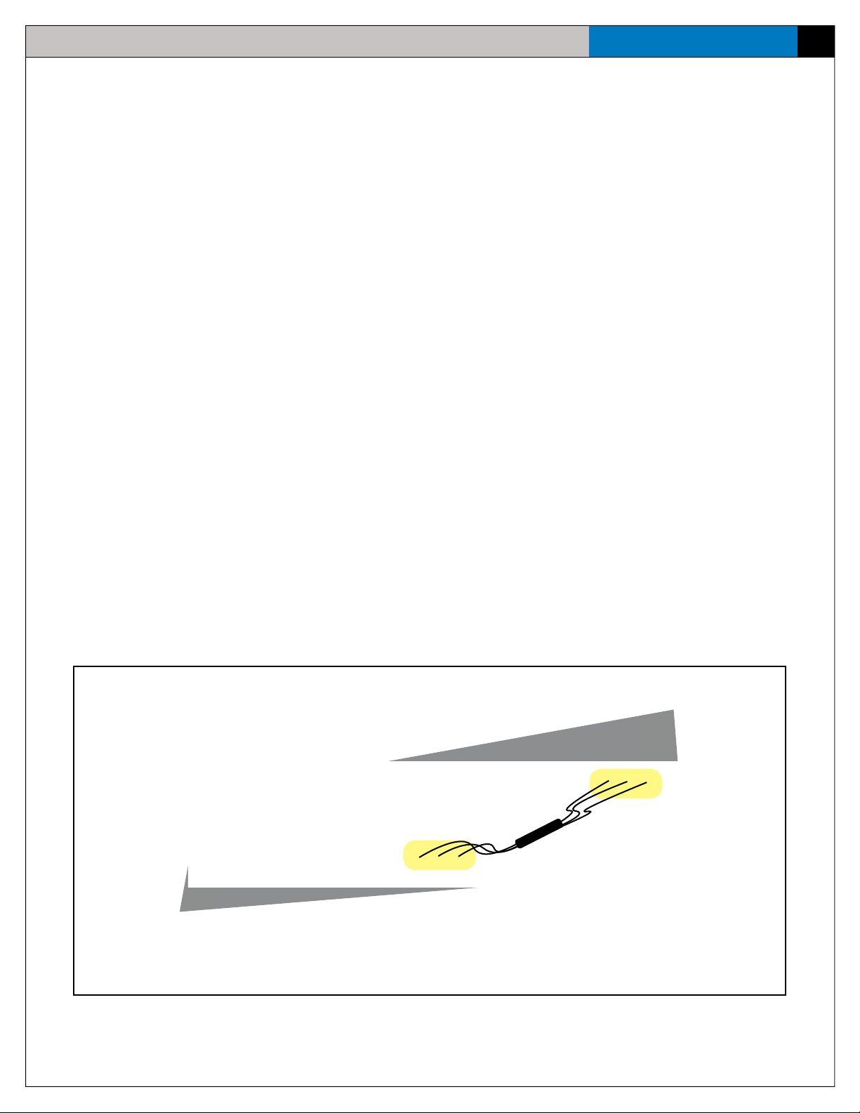
6. Run the Remote Cable from the Thunder Master to the desired location of the Thunder Remote.
Note: The Remote Cable should run under or around the seating area to avoid being stepped on or tampered
with. It can be installed in conduit in locations where the system is used frequently.
11
Figure 12: Run the Remote Cable under seating area.
7. Then, set up the Thunder Remote. Run the power, turn it on, and connect the Remote Cable to the Thunder Remote.
Thunder Remote
(back)
Remote Cable
Thunder Master
Figure 13: Connnect the Thunder Remote’s audio cable to the Thunder Master.
Page 16

12
eVenue Thunder
8. Test multiple audio inputs into the Thunder Remote by checking signal, clarity, and making sure no equipment damage will
occur.
9. After your event, do the following:
• Return all ePods to Travel Ready position.
• Turn off each eVenue product.
• Disconnect all audio devices.
• Disconnect and re-spool audio and power cables.
• Tow the system to your storage location.
Note: When re-spooling long cables, walk the cable head back to its spool, secure it, and use the spool handle to
reel in the rest of the cable.
Setup and Teardown Procedures
Page 17

Hardware Installation
eVenue Thunder
Hardware Installation
This section outlines how to connect and power your eVenue system.
CAUTION: When connecting, all volume controls should be turned down to prevent possible equipment damage;
then, adjust to the desired level after the inputs/outputs are connected.
Thunder Master I/O Connection Panel
This section outlines the I/O connection panel to utilize your eVenue Thunder Master.
Figure 14: Thunder Master I/O Connection Panel
13
1. Mic 1 & 2: Two microphone-level inputs (balanced; female)
2. PC, MP3, CD: Audio input (line-level; stereo; unbalanced; female)
3. External Mix In (Left, Right): Audio input (line-level; balanced; +4 dB; female)
4. Output to ePods (Left, Center, Right): Audio 6-pin XLR connections to ePods (male)
5. From Remote: Bundled, redundant, paired 7-pin XLR with a Cat 5 cable; allows simultaneous control from the Thunder
Remote to the Thunder Master.
Thunder Remote I/O Connection Panel
This section outlines the I/O connection panel to utilize your eVenue Thunder Remote.
Figure 15: Thunder Remote I/O Connection Panel
1. Mic 1 & 2: Two microphone-level inputs (balanced; female)
2. PC, MP3, CD: Audio input (line-level; stereo; unbalanced; female)
3. External Mix In (Left, Right): Audio input from an External Mixer (line-level; balanced; +4 dB; female)
4. Output to ePods (Left, Center, Right): Audio 6-pin XLR connections to ePods (male). Use not required unless Thunder
Remote is used alone with ePods.
5. To Master: Allows simultaneous control from the Thunder Remote to the Thunder Master. This is a bundled,
redundant, paired 7-pin XLR with a Cat 5 cable.
Page 18

14
eVenue Thunder
Hardware Installation
ePod I/O Connection Panel
This section outlines the I/O connection panel to utilize your eVenue ePod(s).
1. Commando-e Remote: Remote connector input for eVenue Commando-e Remote to
raise arm and tilt the Upper Speaker Array. (male)
2. Input: Audio-in from eVenue Thunder Master or Thunder Remote (female)
3. Thru: Used for daisy-chaining multiple ePods together. A 6-pin female XLR plugs into
the Thru connection (male)
Figure 16: ePod I/O Connection Panel
Page 19

Hardware Operation
eVenue Thunder
Hardware Operation
The eVenue system’s setup exibility means that the Thunder Master and Thunder Remote can be used in multiple different
congurations with ePods. They can be set up separately to send audio to a small number of ePods, or they can be used together in
large venues.
For information on connecting the eVenue system in these congurations, see Hardware Installation on page 13.
In any conguration, the basic procedures for connecting and operating the Thunder Master and Thunder Remote are the same, and
they are detailed in this section. Conguration-specic procedures are also explained.
Note: To prevent equipment damage, keep the Thunder Master’s acrylic door closed when not changing audio
settings or connections.
Thunder Remote and Thunder Master
The Thunder Remote’s and Thunder Master’s hardware is labeled in Figure 17, and operation of these products is detailed in
procedures on the following pages.
15
Thunder Remote
Thunder Master
Figure 17: Thunder Remote and I/O (Left) and Thunder Master and I/O (Right). Not all connections and controls are replicated on both units.
1. Remote Volume
2. Mute Selector
3. Master Volume
4. Mic 1 and 2 Mixer Controls
5. CD, MP3, PC Mixer Controls
6. Main Mix
7. Feedback Suppressor
8. Processor
9. UPS
10. Thunder Master I/O Connection Panel
(Thunder Remote’s is on its rear.)
11. Storage Drawer
Page 20

16
eVenue Thunder
Hardware Operation
Connections and Controls
Audio Sources
Mic 1 & 2: To operate a microphone, plug its 3-pin XLR connector (male) into the Mic 1 or Mic 2 input on the I/O connection panel.
Then, adjust the volume using the Mic 1 or Mic 2 faders on the mixer. The eVenue system has no phantom power; therefore, you
should always use a dynamic microphone.
Figure 18: I/O Connection Panel Mic Connections
PC, MP3, CD: To operate a PC, MP3, or CD audio source, connect the desired input device to the I/O connection panel with a 1/8
inch mini (male) auxiliary cable. Ensure the input device’s volume is turned up, but not clipping, when playing through eVenue
Thunder. Adjust the volume of each input using its respective fader on the mixer.
Note: The Thunder Software is an audio source when it is used on a PC that is connected into eVenue. Thunder
Software operation is detailed on page 31 of this manual.
Figure 19: I/O Connection Panel PC, MP3, and CD Connections
External Mixer: To input an External Mixer as an audio source, connect the left and right XLR outputs from your mixer to the
corresponding Ext Mix In inputs on the Thunder I/O connection panel.
Note: CoachComm does not provide an external mixer for use in eVenue Thunder.
Figure 20: I/O Connection Panel External Mixer Connection
Page 21

Hardware Operation
eVenue Thunder
Mixer Controls
Adjustments to the Mixer occur with the Main Mix (Figure 21) and the specic Input Controls (Figure
22).
Main Mix: The ideal position for the Main Mix fader is 0 dB. Leave Program (Push), FX To Main, and
Phones/Control Room knobs fully counterclockwise and CD/Tape to Mix, CD/Tape to Ctrl, and FX Solo
buttons in their out position.
Input Controls: The Mixer provides independent controls for each specic input, including Mic 1
and 2, CD, MP3, and PC (which may include the Thunder Software).
17
Figure 21: Main Mix Controls
• CD input controls correspond to Channels 7 and 8 (labeled CD)
• MP3 input controls correspond to channels 9/10 (labeled MP3)
• PC input controls correspond to channels 11/12 (labeled PC)
Each input’s controls are labeled as detailed below:
1. Gain (a.k.a “Trim”): Sets the input volume. Always turn fully counterclockwise before the
input is connected or disconnected, then adjust to the desired level.
2. Clip: When on, indicates that your signal is distorted
3. High: Adjusts the intensity of the higher frequencies for that input in the mix. Always
start in the 12 o’clock position and adjust to the desired level.
4. Low: Adjusts the intensity of the lower frequencies in the mix. Always start in the 12
o’clock position and adjust to the desired level.
5. Mon: This is not used in eVenue. It should always be turned fully counterclockwise.
6. FX: This is not used in eVenue. It should always be turned fully counterclockwise.
7. BAL (Pan): Pan controls the audio intensity from left to right. Always leave at 12 o’clock
position. (An exception to this rule is for the CD channels. Turn the left fully left, and the
right fully right. Any changes applied to one should be applied to both, equally.)
8. Fader: Gradually increases or decreases audio signal levels for that input.
1
2
3
4
5
6
7
8
Figure 22: Sample Mixe8 Input Controls
Page 22

18
eVenue Thunder
Hardware Operation
Master Volume or Remote Volume
The Master Volume or Remote Volume (for Thunder Remote), whichever is applicable in the conguration, controls all audio outputs
to the connected ePods. It should be turned down (counter-clockwise) when connecting audio inputs to prevent possible equipment
damage, then adjusted to the desired level. The lights surrounding the knob indicate audio level.
Figure 23: The Master Volume knob controls all audio
outputs to the ePods connected to the Master. Note
that this image depicts maximum volume.
Figure 24: The Remote Volume knob controls all
audio outputs to the ePods connected to the Remote.
Note that this image depicts maximum volume.
Processor
The Routing Processor assigns where the input’s path to a specic output goes. The controls are preset for your use, so adjustments
should not be made. For help resetting your Routing Processor to its factory setting, please contact CoachComm’s Customer Service
at 1-800-749-2761. Figure 25 shows the preset conditions for Thunder Master and Figure 26 shows the preset conditions for
Thunder Remote.
Figure 25: Thunder Master Routing Processor
Figure 26: Thunder Remote Routing Processor
Feedback Suppressor
The Feedback Suppressor reduces microphone feedback. As it detects feedback, the notch lter indicators will light up. Adjustment
is not recommended for your use.
Figure 27: Thunder Master and Thunder Remote Feedback Suppressor
Page 23

Hardware Operation
eVenue Thunder
Audio Out
When the Thunder Master and Thunder Remote are used separately to send audio output to ePods, use the Output to ePods
connections on each device’s I/O connection panel.
Figure 28: I/O Connection Panel Output to ePods Connection
Using Thunder Master and Thunder Remote Together
When the Thunder Remote is used together with the Thunder Master, all audio input devices should be connected to the Remote.
(See Figure 29 on the following page.)
Note: An exception to this rule can occur when an audio input is needed at the Thunder Master (e.g., a microphone
input for a halftime awards presentation on the eld). When this is needed, the input is controlled from the
Thunder Master per usual operations.
19
When the Thunder Master and Thunder Remote are used together, ePods should only be connected to the Thunder Master. Use of the
Thunder Remote’s output connection is not recommended unless the Thunder Remote is used alone with ePods.
In this conguration, the Master Volume knob controls system outputs. The two Master Volumes become clones of each other, while
the Thunder Remote’s Remote Volume knob controls no outputs (unless there are ePods plugged directly into the Thunder Remote,
though this is not recommended.)
Follow the procedures in the Connections and Controls section of this manual to operate both products’ various volume and mixer
controls.
Page 24

20
eVenue Thunder
Hardware Operation
Figure 29: When the Thunder Remote and Thunder Master are congured together, all audio devices connect to the Thunder Remote, which is linked to the
Thunder Master, and all ePods are outputs from the Thunder Master
Page 25

Hardware Operation
eVenue Thunder
Using Thunder Master and Thunder Remote Separately
When the Thunder Remote and Thunder Master are used separately, all audio devices should be connected to their respective inputs,
and all necessary ePods should be connected to their respective unit’s I/O connection panel. (See Figure 30 and Figure 31.) Follow
the procedures in the Connections and Controls section to operate both products’ various volume and mixer controls.
21
Figure 30: When the Thunder Master is congured separately, all audio device inputs and ePod outputs connect to it.
Page 26

22
eVenue Thunder
Hardware Operation
Figure 31: When the Thunder Remote is congured separately, all audio device inputs and ePod outputs connect to it.
Page 27

Hardware Operation
eVenue Thunder
ePod
Operate your ePod(s) using the procedures detailed on the following pages.
Commando-e Remote
This section outlines how to operate the Commando-e Remote. The Commando-e Remote is considered the key to the ePod’s motion
control system. The control system will not function when the Commando-e Remote is not plugged in, and will not operate when it is
unplugged.
1
1. Flashlight: Activates when Brake button is held for one second. Deactivates when
Brake is held for one second. (Operates only when plugged into the ePod.)
32
2. Brake: Indicator LED for ePod Brake On/Off
3. Ready: Indicator LED that ePod is ready for deployment
23
54
4. Arrows: Elevates and lowers the Upper Speaker Array
5. Rack Tilt: Tilts the Upper Speaker Array
6. Presets: Store up to four specic Upper Speaker Array positions
6
Figure 32: Use the Commando-E Remote to control the
ePod’s Motion Control System.
Connecting the Commando-e Remote
Plug in the Commando-e Remote to the “Remote” connector on the I/O connection panel, which is located on the side of your ePod.
When connecting or disconnecting this remote, the ePod will beep two times.
Using the Commando-e Remote
When using the Commando-e Remote, hold the selected positioning button and release when it’s in the desired position.
For initial use of the Commando-e Remote with an ePod, it will beep four times to warn of movement. After the initial use, the
beeping will stop, if used continuously. When the Commando-e Remote is not used for 10 seconds and use resumes, it will beep four
times before moving.
Note: Releasing the button(s) will stop the Upper Speaker Array’s movement in its current position.
Creating and Using Presets
Using the Commando-e Remote and the Sound Coverage information on page 25 of this manual, set your Upper Speaker Array
and actuator in the desired position. To create an individual preset for buttons 1, 2, 3, or 4, press and hold the Brake and Ready
buttons at the same time for four seconds until the Commando-e Remote beeps twice. Then, hold the specic numbered button until
it beeps twice.
The Commando-e Remote can be preset into a Travel Ready position for easy travel preparation.
Note: Once a preset is determined, it will remain in the Commando-e Remote’s memory even when used on different ePods.
Page 28

24
eVenue Thunder
Hardware Operation
ePod Status Panel
This section outlines the ePod Status Panel, located on the
lower component case of each ePod. This panel is designed to
allow you to know if the ePod is in use, it cannot extend further,
it is not locked properly, or it is suitable for movement. The
panel shows individual ePod locations and indicates their status
by turning on and off red and green LED lights. The table below
illustrates the qualications for these LED options.
Key Terminology
• Travel Ready: ePod Upper Speaker Array is in the
down position, resting in the cradle
• Roll Level: Right and left level
• Pitch Level: Front and back level
Figure 33: View the ePod’s Status Panel for information about the Motion Control System.
Green Red LED Off
Rack Tilt Fully vertical, i.e., Travel Ready
position
Arm All the way down, i.e., Travel
Ready position
Roll Level ePod roll angle is less than 10°
from level
Tow Bar Up and lock position N/A Down position
Brake On N/A Off
Pitch Level ePod tilt angle is less than 10°
from level
Deploy Ready ePod is level; brake is on; tow bar
is in the up and locked position
Travel Ready Brake is off; arm and rack are in
Travel Ready position
CAUTION: The ePod system will not deploy if the Roll Level or the Pitch Level indicators are red, which indicates
that the ePod is outside of their 10° angle.
Any position that is not fully
vertical
Any position that is not down N/A
ePod roll angle is greater than
10° from level
ePod tilt angle is greater than 10°
from level
N/A If the three Green
N/A If the two Green
N/A
N/A
N/A
qualications are not met
qualications are not met
Page 29

Hardware Operation
eVenue Thunder
Sound Coverage Overview
This section outlines the suggested practices to reach the audio levels desired when using your eVenue Thunder system. It is better
to determine your intended audio coverage at the beginning of the installation procedure. For more on system setup, look at the
Setup and Teardown section on page 8 of this manual. Included is a legend to identify the images used throughout this section.
It is important to consider what areas you would like to cover with sound. You may want to balance audio for your entire audience or
pinpoint certain sections.
Each ePod is estimated to cover approximately 90 degrees of horizontal space, 70 degrees of vertical space, and up to 100 feet of
depth (for maximum impact before dissipation affects sound quality).
Positioning your ePod(s)
In Figure 34, you can see how positioning the ePods straight toward the seating area will impact a select section of your intended
audience.
25
Figure 34: Example of Straight ePod Positioning
Page 30

26
eVenue Thunder
In contrast, to balance audio output across the intended audience, you can angle the ePods so they cover a specic surface area, as
shown in Figure 35.
Hardware Operation
Figure 35: Example of Angled ePod Positioning
Page 31

Hardware Operation
eVenue Thunder
Suggested ePod Placement in Relation to Barriers
Determining the placement of the ePod and the area of sound coverage is also dependent on present barriers, such as fences,
concrete walls, or other obstructions. As shown below, you will need to place your ePods at a position that is not too close or too far
from a barrier or the audience.
27
Figure 36: Sound coverage varies depending upon the ePod’s proximity to barriers.
Page 32

28
eVenue Thunder
Below are two diagrams depicting the least desired locations for your ePods.
In this diagram, the ePod is located too close to a barrier, losing some of the audio you want your audience to hear.
Hardware Operation
Figure 37: Positioning ePods too close to barriers hinders the audio projection.
In this second diagram, the ePod is too far back, resulting in inefcient and less powerful sound coverage for the intended audience.
Figure 38: Positioning ePods too far away from the audience hinders sound quality.
Page 33
Hardware Operation
eVenue Thunder
Positioning your Upper Speaker Array
Once you have followed the Setup Procedures in this manual, test your ePod(s) output and position the Upper Speaker Array(s) to the
desired angle for further coverage specication. For reference, the center point of the Upper Speaker Array will align with the center
point of your intended coverage area.
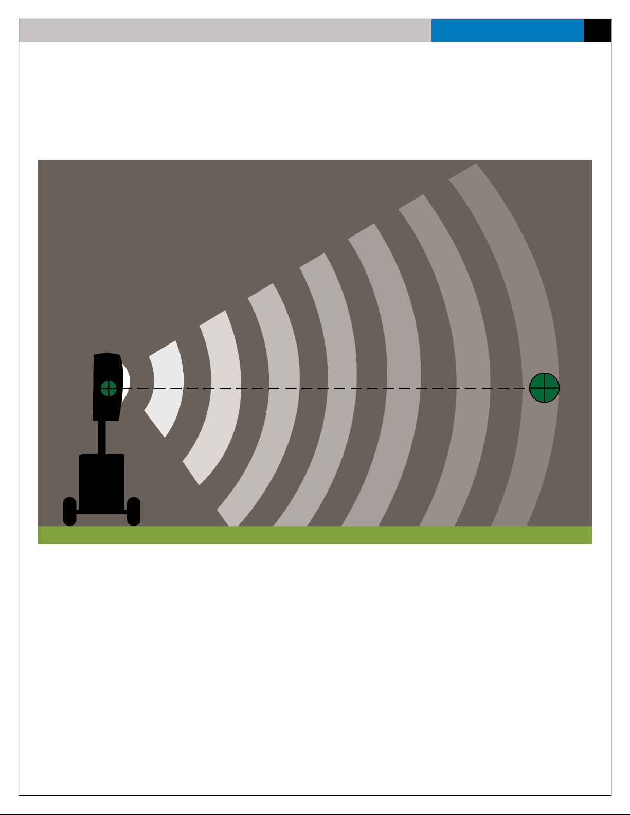
When the Upper Speaker Array is completely vertical, the coverage is limited to the area directly in front of it, losing sound energy as
it extends farther. This is known as Flat Coverage and is shown below.
29
Figure 39: Adjust your ePod Upper Speaker Array’s tilt for at coverage.
Page 34

30
eVenue Thunder
In contrast, to cover a larger range of space at an angle, move the Upper Speaker Array so that its center point is directed toward the
center of your seating area. In the diagram below, Elevated Coverage is shown as the center of the Upper Speaker Array is angled to
meet the center of the seating area.
Hardware Operation
Figure 40: Adjust your ePod Upper Speaker Array’s tilt for elevated coverage.
Page 35

Software Installation and Operation
eVenue Thunder
Software Installation and Operation
The following section details procedures for operating eVenue Thunder Software.
Installation
Minimum Software Requirements
• Microsoft .NET 4.5 Framework (will install automatically, if not present)
• Processor: 1 GHz
• RAM: 512 MB
• Disk Space: 100 MB
• Windows Vista SP2, Windows 7 SP1, Windows 8, or Windows 8.1 (32 and 64 bit for all)
Installation Procedures
1. When the eVenue Thunder Software installation program starts, the InstallShield Wizard will progress you through the
necessary installation steps, including: determining the location of the program on your computer, viewing installation
settings, and entering a license key. To progress through the wizard, click Next on each of the windows as they display.
31
Figure 41: Follow the installation wizard’s prompts to install Thunder Software.
Page 36

32
eVenue Thunder
2. Once the eVenue Thunder program is installing, the screen will display a status bar of the installation progress. If at any
point you need to cancel the installation, select Cancel to stop the installation immediately.
Software Installation and Operation
Figure 42: Thunder Software Installation Wizard’s Status Bar
3. After the installation is complete, the Registration Dialog will appear. This box will contain your Thunder Software’s
25-digit ID number. Call CoachComm’s Customer Service (1-800-749-2761), and press 2 for Service to request the
correct Serial key to activate your license. Once you have the key, enter it in the allotted elds and click OK. You can also
select Trial Run, allowing you to run the program for either a maximum of 200 times or a maximum of 30 days, whichever
comes rst.
Figure 43: Enter your Thunder Software Serial Key to register your license.
Page 37

Software Installation and Operation
eVenue Thunder
Software Overview
eVenue’s Thunder Software assists in organizing and scripting event audio for playback through the eVenue system. A Script created
in Thunder Software is the determined order of songs, announcements, and sound effects that plays through the system. A Script is
made up of multiple Events, which can be audio-only, text-only, or a combination. Within the software, you can control each Event’s
individual playback settings as well.
Figure 44 below details the main functional areas of Thunder Software.
33
Figure 44: Thunder Software Main Screen Overview
A. File Menu (eVenue Icon): Allows you to access multiple software functions for creating, editing, and playing
Scripts.
B. System Clock: Displays your computer’s time of day.
C. Script Modes Button: Toggles the Script display mode between List Mode and Button Mode.
D. Groups: Allow you to create additional Event lists besides the default list to further organize and sort Events for
organized playback.
E. Edit Mode: Allows you to add, delete, or edit the Events and Script and change some of Thunder Software’s
interface options.
F. Volume Master Panel: Allows you to control multiple sound and playback functions during Script creation or
playback.
G. Hot Buttons: Allow access to quickly play frequently used les.
Page 38

34
eVenue Thunder
Software Installation and Operation
File Menu Options
The eVenue Thunder File menu is accessible by clicking on the eVenue logo in the upper left-hand corner.
This menu provides the following options for creating, editing, and playing your Scripts.
• New: Creates a new Thunder Software Script le.
• Open: Allows you to browse your computer’s directory and open an existing Thunder Software
Script le.
• Save: Saves the changes to the open Thunder Software Script le.
• Save As: Saves the current Thunder Software Script as a new le to your local machine.
• Shufe: This playback setting randomly selects Events throughout the Script. Shufed Audio Events play through
completion, and then the software randomly chooses another Event. Shufed Text Events or Combination (Audio and
Text) Events are shown on the teleprompter at random, but the user must manually advance the script after the Event is
completed. This is a safety feature to prevent the next Event from starting in the middle of the announcement.
• Continuous: This playback setting moves through Events in the order they are arranged in the Script. Once the Script
ends, playback will start over again and continue in that order until stopped by a user. As in the Shufe playback setting, a
Text Event or Combination Event must be manually advanced.
Note: In either Shufe or Continuous playback setting, if an Event is set to Auto-Start, its audio or teleprompter will
begin automatically.
• Add Event: Allows you to add another Event to the Group that is currently in use. The new Event will be added to the
bottom of the current Event list.
• Zoom: Allows you to increase or decrease the Event bar’s size.
• WPM (Words Per Minute): Changes how quickly the teleprompter reads through an Event’s attached text.
Alter the speed to be as fast or slow as needed for your announcer.
Figure 45: eVenue Logo/File
Menu Button
• Import: Allows you to open and use Thunder Software les that have been created and exported by other
program users, allowing you to move script, audio, and text les from computer to computer. The le must
have the extension .exp in order to be imported. Once a le is imported, it can only be viewed and played.
In order to make changes, save the le locally to your computer.
• Export: Allows you to format and export the Thunder Software Script in order for other program users to
import it on another computer, if desired. The Export function packages and reformats audio les and all
Script settings. The exported le’s extension will be .exp.
Edit Mode Menu
Enter Edit Mode by clicking on the pencil icon in the upper left-hand corner. Additional buttons will then display, and
they are listed below:
• Up Arrow: The selected Event will move up one spot in the Event order.
• Down Arrow: The selected Event will move down one spot in the Event order.
• Addition Sign: A new Event is added at the bottom of the list.
• Trash: The selected Event will be deleted.
You may enter Edit Mode, even while a script is playing. This allows for easy reorganization and updates to Events in
real-time at your venue during playback.
Figure 46: Thunder Software Edit Mode Options
Page 39

Software Installation and Operation
eVenue Thunder
Script Modes
The Script Mode button toggles between two different Display Modes:
List Mode
The List Mode displays the Script’s Events in a precise sequential list. This is the display mode that appears on startup. List Mode’s
display allows you to view more detail about specic Events and to set up auto-play Events in your Script. In this mode, the screen
displays the following details:
• Event name
• Play Count (How many times the Event has been played. The number resets when Thunder Software is closed.)
• Event Duration
• Auto-Play On/Off
• The presence of attached audio or text
• Progress (How much time is remaining in the Event)
35
Figure 47: List Mode Display
Note: In this mode, only one Event may be playing at a time.
Button Mode
The Button Mode displays the Script’s Events as boxes arranged on the screen. Button Mode’s display allows you to manually
select Events during playback. Unlike List Mode, this mode does not require a specic ordered arrangement; therefore, there is no
auto-play feature. This prevents Events from automatically starting, so you will need to select Events to play. Each box displays the
following:
• Event name
• Play Count (How many times the Event has been played. The number resets when Thunder Software is closed.)
• Progression of the Event, as indicated by a green bar
Figure 48: Button Mode Display
Note: Unlike List Mode, multiple Events can be playing at the same time no matter if they contain text or not. You
can have as many Events going as needed. However, as always, when a Text Event is complete, you must
manually advance all other Events, including any that were playing together.
Page 40

36
eVenue Thunder
Software Installation and Operation
Volume Master Panel
The Volume Master Panel functions as follows:
Audio Level Meter: Shown at the top of the volume panel, representing the volume levels of the
audio. The top bar displays the left output, while the bottom bar displays the right output volume.
Volume Control: Allows you to manually raise or lower the fader bar to increase or decrease the
playback volume.
Max Volume: Immediately places the playback volume at its highest point.
Min Volume: Immediately places the playback volume at its lowest point.
Fade/Stop: Immediately starts to lower the volume and continues to lower until it reaches the lowest
point, stopping the Event. It can be used at any level of volume.
Mute: Immediately mutes the playback volume without stopping the current track.
Play: Plays any Event that is currently selected. While an Event plays, this button becomes
the Pause button.
Next: Skips the current Event and moves to the next.
Stop: Immediately stops any active Event.
Figure 49: Volume Master Panel
Group Tabs
Thunder Software’s Group tabs allow you to set up four additional Event lists in addition to your main Script. These tabs are helpful
for organizing your playback workow and for sorting and nding specic Events. When viewing a Group tab, return to your main
script by clicking on the highlighted tab.
To edit the Group names, enable Edit mode and select the tab that needs to be changed. A white edit box will appear on the same
line as the tabs’ names, allowing you to change the name. Once the new name is entered, click on any of the group tabs in order for
the change to become active.
Figure 50: Entering a Group Name
Page 41

Software Installation and Operation
eVenue Thunder
Operation
Create a New Script
1. To create a new script, open eVenue Thunder Software and click New under the File menu.
2. Access Edit Mode and select the addition sign to add an Event to your script.
3. Double-click the new Event to open the Event Editor box. From this box, all the Event’s individual settings can be
determined, including adding audio and text les.
Add/Change Event Audio and Text
Associate the appropriate les to your Event based on one of the Event types below:
37
Figure 51: Event Editor Details
• Audio-Only Events: To add an audio le to an Event, drag an audio le from your computer’s directory to the Script. (The
software will enter Edit Mode and open an Event Editor box automatically if not already open.) Or double-click to access
the Event Editor and click on the small button with a speaker icon to browse your computer’s directory.
Note: Thunder Software supports .wav, .mp3, .aiff, and .wma le formats.
• Text-Only Event: To add text to the Event, double-click to access the Event Editor. Then, type or copy and paste text in the
white box on the right.
• Combination Audio + Text Event: An Event can have both audio and text les attached to it. While the teleprompter
progresses through the text le, the audio le will also play.
Add/Change Hot Buttons
Hot Buttons are located on the main Thunder Software screen, and they allow quick access to commonly used audio les during
Script playback and when the Script isn’t playing.
To create or edit a Hot Button, enable Edit Mode, then select a Hot Button to display its Event Editor box. (This box is similar to the
main Event Editor that displays for the Script Events, but unlike the Script Events, text les cannot be added to Hot Buttons. Hot
Buttons can only have audio les added to them.) Add or change the Hot Button’s associated audio le and settings using this box.
You can also drag an audio le from your computer’s directory to the Hot Button. (The software will enter Edit Mode and open an
Event Editor box automatically if not already open.)
Page 42

38
eVenue Thunder
Software Installation and Operation
Adjust Event Settings
Adjust each Event’s settings by accessing the Event Editor and using these features:
• Event Name: In this eld, enter an Event name to display in the Script. If there is no Event Name entered before an audio
le is attached, the Event will take the name of the audio le.
Note: This name is not permanent and can be changed at any time.
Event Editor Checkbox Settings
• Auto-start: Enabling Auto-start allows the Event to start as soon as the previous Event nishes. Events can auto-play
with the Shufe or Continuous playback setting. The auto-play will select the next song in the list that has the function
activated.
• Fade-in: Enabling Fade-in causes the Event’s audio to start off quiet and then slowly increase until it hits the desired
volume.
• Fade-out: Enabling Fade-out causes the Event’s audio volume to slowly decrease toward the end of the le. The volume
will decrease until the audio le stops.
• Stop on Text End: Enabling Stop on Text End applies only if there is both a text le and an audio le attached to the
Event. When enabled, the audio and teleprompter progress through the Event, and the associated audio le ends after the
teleprompter reaches the end of the text.
Note: When the Event nishes, the user will still have to manually move on to the next Event because of the text le attached.
• Quick Fade on Stop: Enabling Quick Fade on Stop functions similarly to the Fade-out, except that it applies to a manual
stop. When enabled in an Audio or Combination Event, if you stop the Event, the audio will fade to stop, rather than stop
immediately.
Figure 52: Event Settings Checkboxes
Page 43

Software Installation and Operation
eVenue Thunder
Event Volume Settings
This function restricts the maximum volume that a specic Event reaches. The overall volume can still be increased or decreased in
the Main Volume Panel, but the amount it can be altered is strictly correlated to how the volume is set within the Event’s settings.
For example, if you create a Combination Event, and the associated audio le needs to have a lower volume, you can manually set
the Event Volume lower, so it will drop as soon as the Event starts and then readjust to the default for the next Event. All the options
on the Master Volume Panel will still work for Events with specic volume settings, including Mute, Max Volume, and Min Volume.
Figure 53: Event Volume Settings Detail
Event Start and End Point Settings
You can adjust the start and end times of an audio le associated with an Event. To do so, drag the green and red scrubber bars left
or right to change the start and end times. The time in between the green and red scrubber bars is the audio le’s duration (which is
displayed just below the Event name). You can also type specic times in the two white boxes below the bar.
39
Figure 54: Adjusting Event Start and End Time
Page 44

40
eVenue Thunder
Open and Play a Script
1. To open an existing script, double click on the Script le from your computer’s directory, or open eVenue Thunder Software
and click Open under the File menu. Then, browse your computer for the Script le and select it.
2. Verify that Thunder Software is NOT in Edit Mode.
3. Begin playback by double-clicking on the rst Script Event or selecting the Event with a single click and clicking Play on
the Volume Panel.
4. Once an Event is playing, it can be paused, stopped, or skipped. The volume can also be adjusted at any time.
5. A Text or Combination Event will display a teleprompter for the text. Once the text is read, manually advance to the next
Event by clicking the next arrows.
Software Installation and Operation
Figure 55: Example Teleprompter Window
You may enter Edit Mode, even while a script is playing. This allows easy reorganization and updates to Events in real-time at your
venue during playback.
Page 45

System Maintenance and Storage
eVenue Thunder
System Maintenance and Storage
1. If the system is exposed to rain, dry all parts of the eVenue Thunder System carefully, including cables and connectors.
2. Always make sure that nuts and bolts are secure prior to and after moving or operating.
3. Connect or disconnect cables by holding the connectors (not the sheath of the cable) and pressing the release button if
applicable.
4. When reeling cables, pull the connector back to the reel location and secure it. Then, re-spool the cable by hand from this
position so the connector does not become damaged.
5. It is recommended that the eVenue system be stored in a climate-controlled environment when not in use.
6. Storage Temperature: If a climate-controlled storage space is not available, eVenue equipment can be stored in
temperatures ranging from 5° to 130° F. However, when going from cold to warm environments, electronics can form
condensation, which can cause damage to the electronic components. If storing your system in these type of conditions,
wait for the equipment to acclimate to the ambient temperature before using.
Operating Temperature:
A. If using your eVenue system at or near freezing temperatures, it is recommended that you warm speakers up
gradually by playing at a low volume for at least 20 minutes before playing at loud levels.
41
B. You may notice performance issues when operating above the ambient temperature of 122° F.
7. Store eVenue’s Master and ePods with their brakes on and with the tow bar in the upright position.
8. Verify that system power and UPSs are off before storing the system.
Storage Dimensions
The following graphics depict the dimensions of each part of the eVenue Thunder system.
Width: 32 in.
ePod
Length: 71 in.
Width: 32 in.
Thunder
Master
Length: 71 in.
Width: 23 in.
Thunder
Remote
Length: 22 in.
Height: 19 in.
Travel Ready Height: 71 in.
Height: 61 in.
Page 46

42
eVenue Thunder
System Maintenance and Storage
Tie Down Points
There are three recommended tie-down points on the eVenue ePods and Thunder Master: two near the tow bar and one through the
hitch receiver.
Figure 56: Tie-down points near tow bar
Figure 57: Tie-down point through hitch receiver
Page 47

Signal Flow Diagrams
Signal Flow Diagrams
The following images depict specic audio signal details for the eVenue system.
eVenue Thunder
43
Figure 58: The Thunder Remote’s and Thunder Master’s I/O Connection Panels contain all system connections.
Disclaimer: Figure 58 depicts all of the connections available from the eVenue Thunder I/O Connection Panel;
however, this diagram is only intended to show overall connectivity. If you need information on setting up
your specic system, please go to the Connections and Controls section on page 16 of this manual for the
congurations we recommend.
Page 48
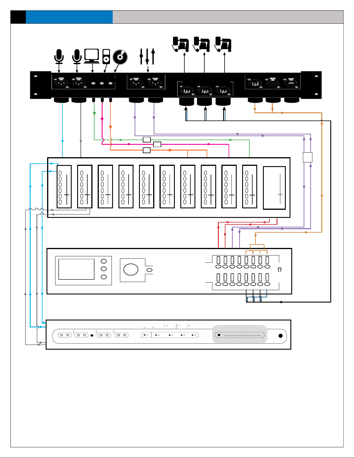
44
eVenue Thunder
Thunder Master Audio Signal Flow
Signal Flow Diagrams
I/O Panel
Mixer
MIC 1 MIC 2
EXT MIX ININPUTS
PC MP3 CD
ISO
ISO
ISO
Mic 1 Mic 2 PCMP3CD, RightCD, Le3 4 5 6
OUTPUT TO ePods
LEFT CENTER RIGHT
FROM REMOTE
A B
ISO
Output to ePods
From Remote
External Mixer
L R
Insert Out 1
Insert Out 2
Processor
Insert In 1
Insert In 2
Input Signal
Signal Clip
System
Bypass
Feedback
Suppressor
Figure 59: Thunder Master Audio Signal Flow
A
Ext
Mix In
Inputs
Mute
112233445566778
Outputs
Mute Mute
Mute
B
Filter
Lock
Program Edit
Panic Mode
Quick
Filter
Adjust
Edit
Stereo
Setup Filter Learn
Preset 1 2 3 4
Mono
Display ADisplay
Menu
Function
Parameter
Notch
Wide
Reset
L R
Mix In
Mute
MuteMute
MuteMute
Mute
L C R S
Notch Filters Active
41 2 3 5 6 7 8 9 10 1112 1314 15 16
L
MuteMuteMute
MuteMute
B
R
Mute
Program
8
Where Output 8 is
subwoofer to ePods
Port
Power
Page 49
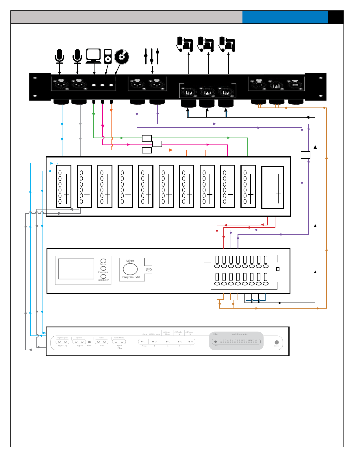
Thunder Remote Audio Signal Flow
Menu
Function
Parameter
Program Edit
Adjust
Edit
Reset
Setup
Filter Learn
Stereo
Mono
Display ADisplay
B
Preset
123
4
Filter
Lock
Notch Filters Active
412356789101112131415
16
Power
Input Signal
Signal Clip
System
Bypass
Notch
Wide
Panic Mode
Quick
Filter
Signal Flow Diagrams
eVenue Thunder
45
I/O Panel
Insert Out 2
Insert In 1
Insert In 2
MIC 1 MIC 2
INPUTS
PC MP3 CD
Mic 1 Mic 2 PCMP3CD, RightCD, Le3 4 5 6
Mixer
Insert Out 1
Processor
EXT MIX IN
ISO
ISO
ISO
OUTPUT TO ePods
LEFT CENTER RIGHT
Mix In
Inputs
Mute
112233445566778
Outputs
Mute Mute
Mute
L R
A
Ext
Mix In
MuteMute
Mute
L
TO MASTER
A B
ISO
External Mixer
Output to ePods
To Master
R
L
Mute
MuteMute
L C R
MuteMuteMute
MuteMute
Program
8
S
Where Output 8 is
subwoofer to ePods
Port
Mute
R
B
Feedback
Suppressor
Figure 60: Thunder Remote Audio Signal Flow
Page 50

46
eVenue Thunder
System Specifications
System Specifications
Thunder Master
Wheelbase: 50.5 in.
Track (Center-to-Center of Wheels): 26.25 in.
Length: 71 in.
Width: 32 in.
Height: 61 in.
Weight: Approx. 750 lb.
Ground Clearance: 6.5 in.
Turn Radius: 174 in.
Maximum Left to Right Tow Bar Angle: ± 35°
Up and Down Tow Bar Angle (During Tow): -5° to 20°
Maximum Operational Speed: 5 mph
Tire Type: Flat-free, non-marking
Tread: Turf
Power Requirements: 120 V dedicated AC circuit for three-prong, 15 amp u-ground Edison plug. Only one
Thunder Master allowed per circuit.
Power Cable Length: 150 ft.
Audio Cable Length: 200 ft.
Battery Backup: Yes, Uninterruptible Power Supply
Thunder Remote
Power Requirements: 120 V dedicated AC circuit for three-prong, 15 amp u-ground Edison plug. Only one
Thunder Remote allowed per circuit.
UPS: Yes, Uninterruptible Power Supply
Length: 22 in.
Width: 23 in.
Height: 19 in.
Weight: Approx. 135 lb.
Page 51

System Specifications
ePod
Wheelbase: 50.5 in.
Track (Center-to-Center of Wheels): 26.25 in.
Length: 71 in.
Width: 32 in.
Height:
Travel Ready 71 in.
Deployed 8 ft.
Weight: Approx. 800 lb.
Ground Clearance:
Travel Ready 6.5 in.
Deployed 2 in.
eVenue Thunder
47
Turn Radius: 174 in.
Maximum Left to Right Tow Bar Angle: ± 35°
Up and Down Tow Bar Angle (During Tow): -5° to 20°
Maximum Operational Speed: 5 mph
Tire Type: Flat-free, non-marking
Tread: Turf
Power Requirements: 120 V dedicated AC circuit for three-prong, 15 amp u-ground Edison plug. Only
one eVenue ePod allowed per circuit.
Power Cable Length: 150 ft.
Audio Cable Length: 200 ft.
UPS: Yes, Uninterruptible Power Supply
Maximum Forward/Rear Incline: 10°
Maximum Right/Left Incline: 10°
Maximum Deployable Incline: Less than 10°
Audio Coverage: 90° horizontal, 70° vertical
Frequency Response: 50 Hz to 20 kHz ± 3 dB
Amp Protection: Multi-stage system limiting and protection
Amp Total Power Output: 4000 watts
Page 52

48
eVenue Thunder
Product Support and Warranty
Product Support and Warranty
CoachComm offers product support from 8:00 a.m. to 5:00 p.m. Central Time, Monday through Friday. Depending on the details
of your maintenance/support plan you may have access to CoachComm’s after-hours support line (800-749-2761). CoachComm,
LLC support and service personnel are ready to help you with any issues you may have. All questions and/or requests for a Return
Authorization Number should be directed to the Customer Service department:
Customer Service Department
CoachComm, LLC
Voice: 800-749-2761 or 334-321-2300
Fax: 866-793-SERV (7378) or 334-821-0397
[email protected]
Sending Equipment for Repair or Maintenance
Do not send any equipment directly to the factory without rst obtaining a Return Material Authorization (RMA) Number. Obtaining a
Return Material Authorization Number will ensure that your equipment is handled promptly. In addition, CoachComm personnel may
provide a Service Request Form (SRF) for you to complete and return with your equipment.
If a CoachComm Customer Service or Support representative directs you to send equipment to us for repair or maintenance, all
shipments of CoachComm products should be made via UPS, or the best available shipper, prepaid and insured. The equipment
should be shipped in the original packing carton; if that is not available, use any suitable container that is rigid and of adequate
size to surround the equipment with at least four inches of shock-absorbing material. All shipments should be sent to the following
address and must include a Return Material Authorization Number:
CoachComm, LLC Customer Service Department
Attn: Return Material Authorization #
205 Technology Parkway Auburn, AL 36830-0500
Product returns should follow this same procedure.
Warranty Information
Limited Warranty CoachComm, LLC products are warranted to be free from defects in materials and workmanship for a period of one
year from the date of sale to the end user.
The sole obligation of CoachComm, LLC during the warranty period is to provide, without charge, parts and labor necessary to
remedy covered defects appearing in products returned prepaid to CoachComm, LLC. This warranty does not cover any defect,
malfunction or failure caused by circumstances beyond the control of CoachComm, LLC, including but not limited to unreasonable
or negligent operation, abuse, accident, failure to follow instructions in the Operating Manual, defective or improper associated
equipment, attempts at modication and/or repair not authorized by CoachComm, LLC, inbound shipping, and shipping damage.
Products with their serial numbers removed or effaced are not covered by this warranty. This limited warranty is the sole and
exclusive express warranty given with respect to CoachComm, LLC products. It is the responsibility of the user to determine before
purchase that this product is suitable for the user’s intended purpose. ANY AND ALL IMPLIED WARRANTIES, INCLUDING THE IMPLIED
WARRANTY OF MERCHANTABILITY ARE LIMITED TO THE DURATION OF THIS EXPRESS LIMITED WARRANTY. NEITHER COACHCOMM,
LLC NOR ANY DEALER WHO SELLS EVENUE PRODUCTS IS LIABLE FOR INCIDENTAL OR CONSEQUENTIAL DAMAGES OF ANY KIND.
Page 53

Product Support and Warranty
eVenue Thunder
49
This page is intentionally blank.
Page 54

CoachComm, LLC
205 Technology Parkway
Auburn, Alabama 36830
1.800.749.2761
www.coachcomm.com
©2017 CoachComm, LLC. All rights reserved. eVenue™ and eVenue Thunder™ are trademarks of CoachComm, LLC. The CoachComm logo is a registered trademark of CoachComm, LLC. All
product names, logos, and brands are the property of their respective owners. The eVenue ePod is a patent-pending design, manufactured in the USA.
Document Reference: 2017.06 D0000140_E
 Loading...