

Page 1
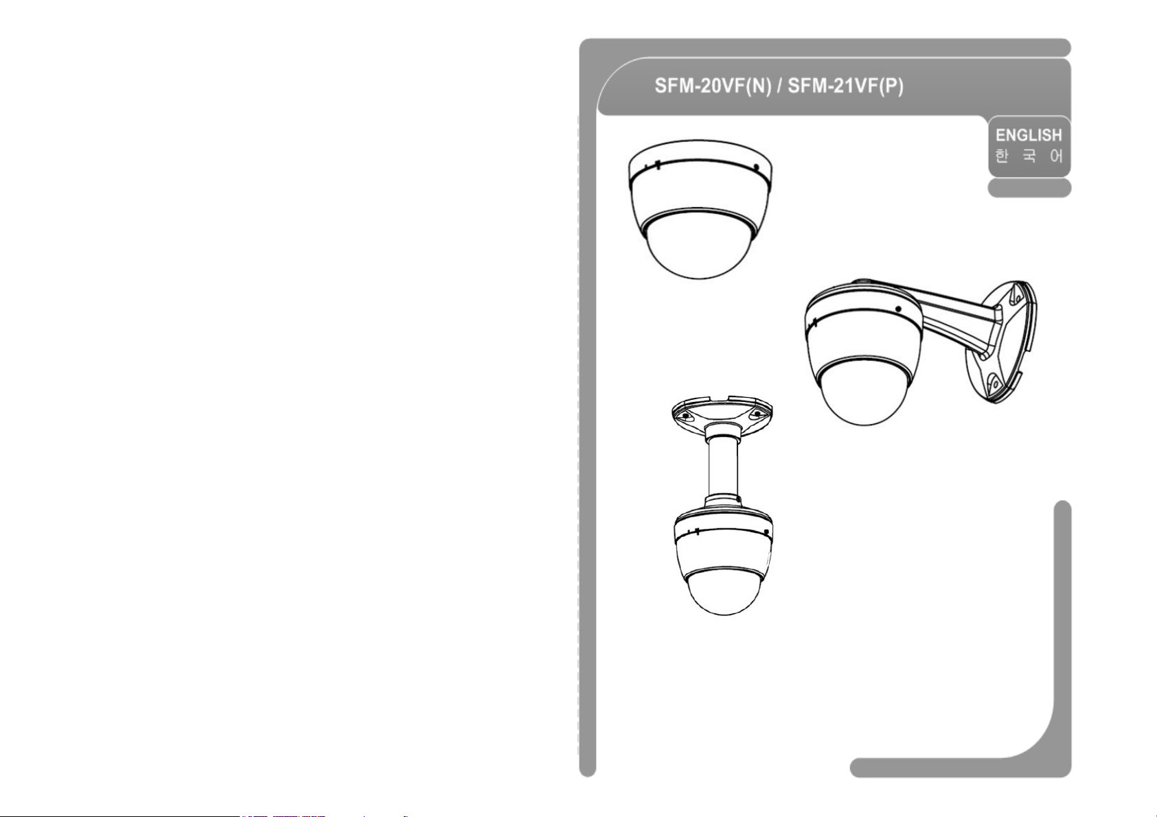
Mini PTZ Dome Vari-focal Camera SFM-2xVF(N/P)
User’s Manual Ver 1.1
Page 2
Mini PTZ Dome Vari-focal Camera SFM-2xVF(N/P)
User’s Manual Ver 1.1 (3810-0215B)
Page 3
Warnings
a risk of electric shock to persons.
manufacturer's instructions and use only mounting accessories recommended by
Cautions
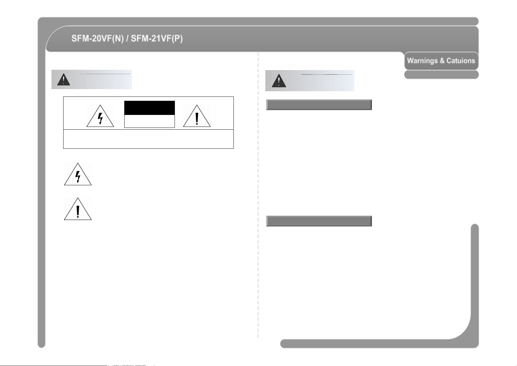
CAUTION
RISK OF ELECTRIC
SHOCK DO NOT OPEN
CAUTION : TO REDUCE THE RISK OF ELECTRICAL SHOCK, DO NOT OPEN COVERS.
NO USER SERVICEABLE PARTS INSIDE.
REFER SERVICEING TO QUALIFIED SERVICE PERSONAL.
This lightning flash with arrowhead symbol is intended to alert the
user to the presence of un-insulated "dangerous voltage" within the
product's enclosure that may be of sufficient magnitude to constitute
This exclamation point symbol is intended to alert the user to the
presence of important operating and maintenance (servicing)
instructions in the literature accompanying the appliance.
WARNING : TO PREVENT THE RISK OF FIRE OR ELECTRIC SHOCK HAZARD,
DO NOT EXPOSE THIS CAMERA TO RAIN OR MOISTURE.
Important Safeguard
◎ Read all of the safety and operating instructions before using the product.
◎ Save these instructions for future reference.
◎ Do not use attachments or accessories unless recommended by the appliance
manufacturer as they may cause hazards, damage product and void warranty.
◎ Do not use this product near water or moisture.
◎ Do not place or mount this product in or on an unstable or improperly supported location.
Improperly installed product may fall, causing serious injury to a child or adult, and
damage to the product. Use only with a mounting device recommended by the
manufacturer, or sold with the product. To insure proper mounting, follow the
manufacturer.
◎ This product should be operated only from the type of power source indicated on the
marking label.
Precautions
◎ Before using, make sure power supply and others are properly connected.
◎ While operating, if any abnormal condition or malfunction is observed, stop using the
camera immediately and then contact your local dealer.
◎ Do not disassemble or tamper with parts inside the camera.
◎ Do not drop or subject the camera to shock and vibration as this can damage camera.
◎ Care must be taken when you clean the clear dome cover. Especially, scratch and dust
will ruin your quality of camera.
◎ Do not install the camera in areas of extreme temperature, which exceed the allowable
range.
◎ Avoid installing in humid or dusty places.
◎ Avoid installing in places where radiation is present.
◎ Avoid installing in places where there are strong magnetic fields and electric signals.
◎ Avoid installing in places where the camera would be subject to strong vibrations.
◎ Never expose the camera to rain and water.
Page 4
Features
Reserved Preset
-------------------------------------------------------------------------------------
23
------------------------------------------------- 6
MENU
------------------------------------------ 29
Product
Installation
Operation
Check points before Operation ------------------------------------------------------------------ 22
Preset and Pattern Function Pre-Check ------------------------------------------------------ 22
Starting OSD Menu --------------------------------------------------------------------------------- 23
PRESET ----------------------------------------------------------------------------------------------- 24
SWING ------------------------------------------------------------------------------------------------- 24
PATTERN --------------------------------------------------------------------------------------------- 25
GROUP ------------------------------------------------------------------------------------------------- 26
Others Functions ------------------------------------------------------------------------------------ 27
OSD Display of Main Screen --------------------------------------------------------------------- 28
------------------------------------------------- 8
------------------------------------------------- 9
------------------------------------------------- 22
General Rules of Key Operation for Menu -------------------------------------------- 29
MAIN MENU ----------------------------------------------------------------------------------- 29
DISPLAY SETUP ---------------------------------------------------------------------------- 29
Compass Direction Setup ------------------------------------------------------------------- 30
CAMERA SETUP ---------------------------------------------------------------------------- 30
MOTION SETUP ----------------------------------------------------------------------------- 32
PRESET SETUP ----------------------------------------------------------------------------- 34
SWING SETUP ------------------------------------------------------------------------------- 36
PATTERN SETUP --------------------------------------------------------------------------- 37
GROUP SETUP ------------------------------------------------------------------------------ 38
SYSTEM INITIALIZE ------------------------------------------------------------------------ 40
Specifications -------------------------------- 42
Page 5
Features
◎
For jog operation using a controller, since ultra slow speed 0.05
°
/sec can be
Camera Specifications
◎ CCD Sensor : 1/3" Interline Transfer CCD (Variable Focus Lens Model).
◎ Magnification : Variable focus lens model (3.8mm~9.5mm), size 42x42 mm
◎ Day & Night Function.
◎ Independent & Simultaneous Camera Characteristic Setup in Preset operation.
Powerful Pan/Tilt Functions
◎ Max. 360°/sec high speed Pan/Tilt Motion.
◎ Using Vector Drive Technology, Pan/Tilt motions are accomplished in a shortest
path. As a result, time to target view is reduced dramatically and the video on the
monitor is very natural to watch.
reached, it is very easy to locate camera to desired target view. Additionally it is
easy to move camera to a desired position with pan/tilt movement.
Preset, Pattern, Swing, Group Functions
◎ Max. 127 Presets are assignable and characteristics of each preset can be set up
independently, such as White Balance, Auto Exposure, Label and so on.
◎ Max. 8 set of Swing action can be stored. This enables to move camera repetitively
between two preset positions with designated speed.
◎ Max. 4 of Patterns can be recorded and played back. This enables to move camera
to follow any trajectory operated by joystick as closely as possible.
◎ Max. 8 set of Group action can be stored. This enables to move camera repetitively
with combination of Preset or Pattern or Swing. A Group is composed of max. 20
entities of Preset/Pattern/Swings.
PTZ(Pan/Tilt/Zoom) Control
◎ With RS-485 communication, max. 255 of cameras can be controlled at the
same time.
◎ Pelco-D, Pelco-P, Panasonic Old/New, Bosch or Sams E/T protocol can be
selected as a control protocol in the current version of firmware.
OSD(On Screen Display) Menu
◎ OSD menu is provided to display the status of camera and to configure the
functions interactively.
◎ The information such as Camera ID, Pan/Tilt Angle, Alarm Input and Preset
can be displayed on screen.
Alarm I/O Functions
◎ 4 alarm sensor Inputs are available.
◎ To reject external electric noise and shock perfectly, alarm sensor Input is
decoupled with photo coupler.
◎ The signal range of sensor input is from DC 5.0 to 12.0 volts to adopt various
applications.
◎ If an external sensor is activated, camera can be set to move to the
corresponding Preset position.
6 7
Page 6
Basic Components
-Donot
detach
protection
vinyl
from
the
bubble
before
finishing
all
installation
process
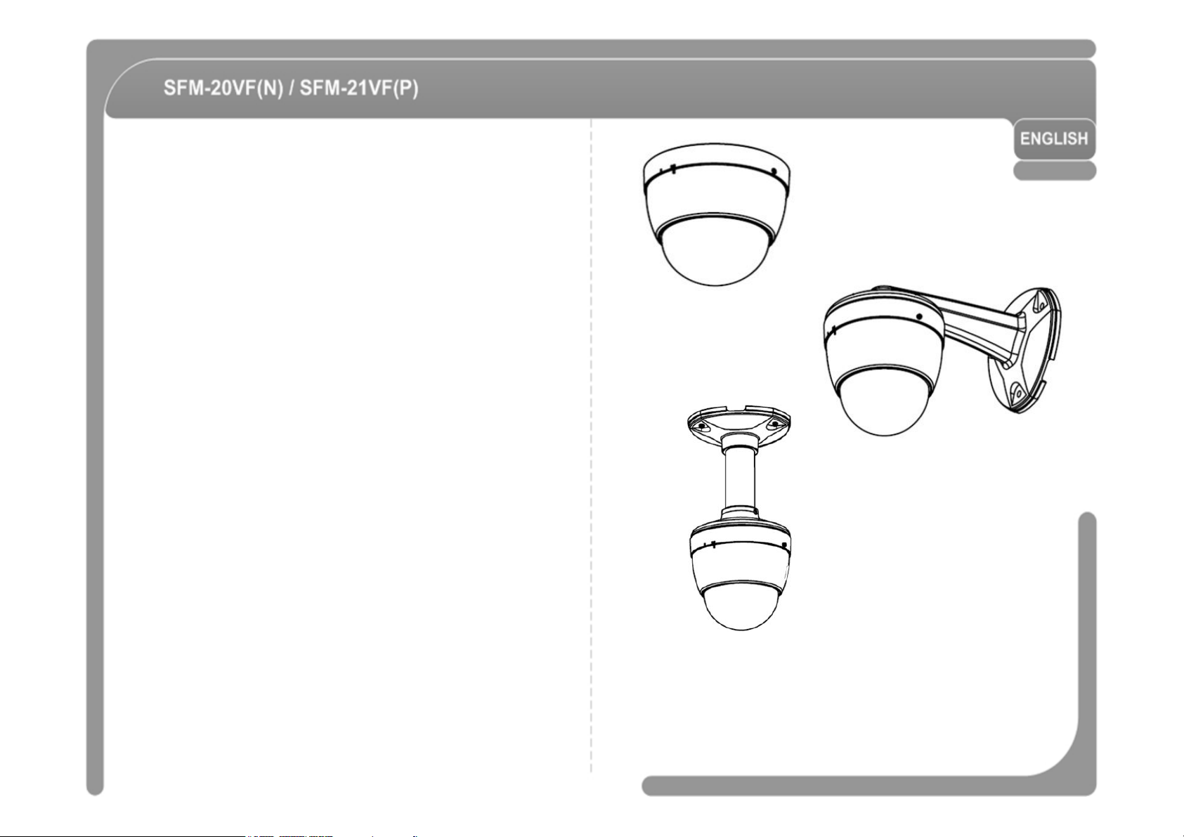
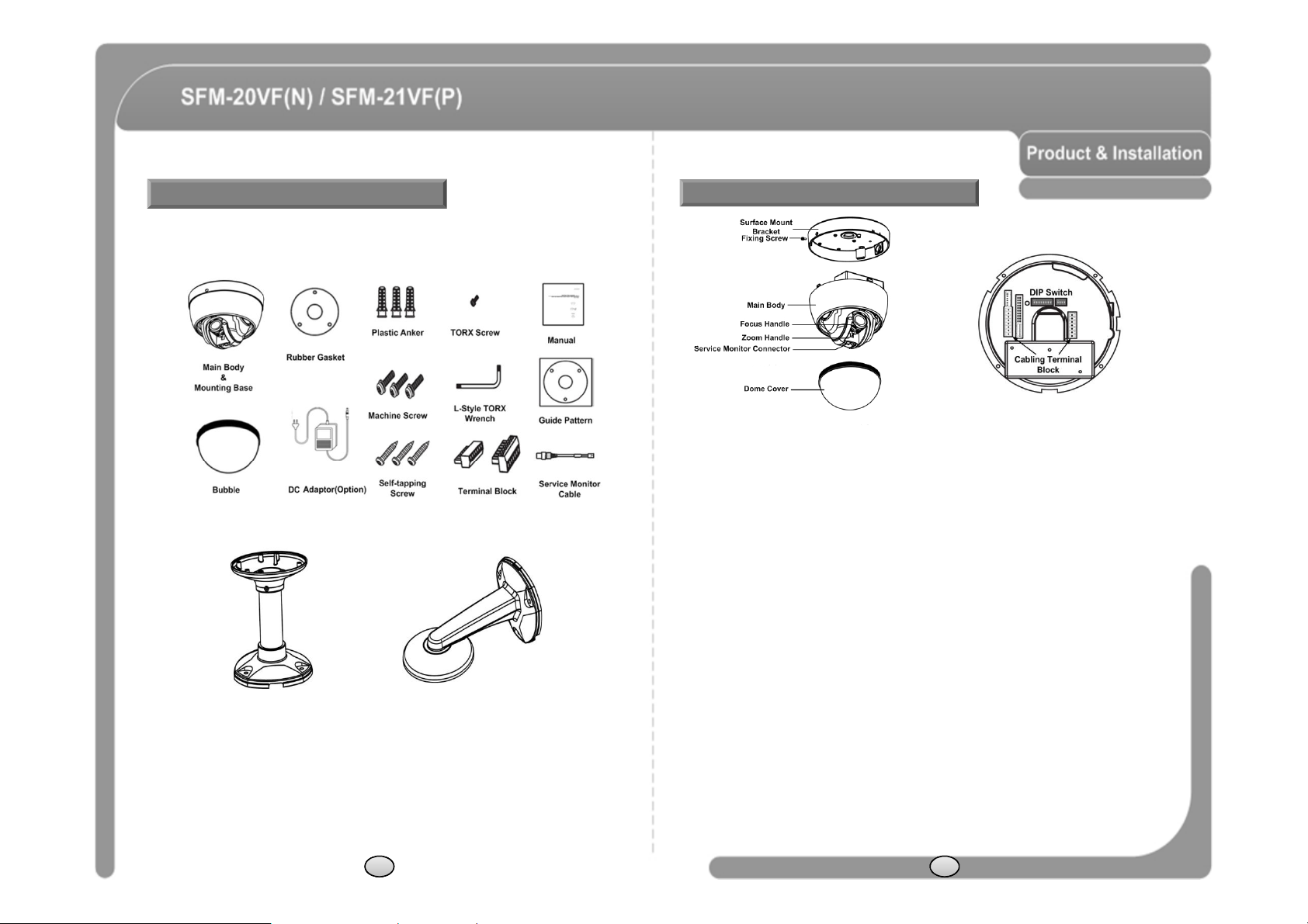
Product & Accessories (SFM-20VF(N), SFM21VF(P))
Options
● Pendant ● Wall
Parts Name & Function
Main Unit / Surface Mount Bracket Back of Main Unit
◎ Dome Cover (Bubble)
to protect the bubble from scratches or dust. Selectable clear or smoke types.
◎ Surface
- This is used to install the camera directly on the ceiling. After separating this cover first
and then attach this directly to ceiling. Camera must be assembled at the last stage.
◎ Fixing Screw
- Fixes main unit to surface mount bracket.
◎ Cabling Terminal Block
- During installation, Power, Video, Communication, Alarm Input cables are connected
on to this cabling terminal block.
◎ DIP Switch
- Adjusts camera ID and protocols.
◎ Focus Handle
- Adjusting the focus lens (FAR/NEAR).
◎ Zoom Handle
- Adjusting the zoom lens (TELE/WIDE).
◎ Service Monitor Connector
- User service monitor connector to set camera angle and focus when installing.
8 9
Page 7
DIP Switch Setup
ON
OFFONPANA.. , 9600 bps
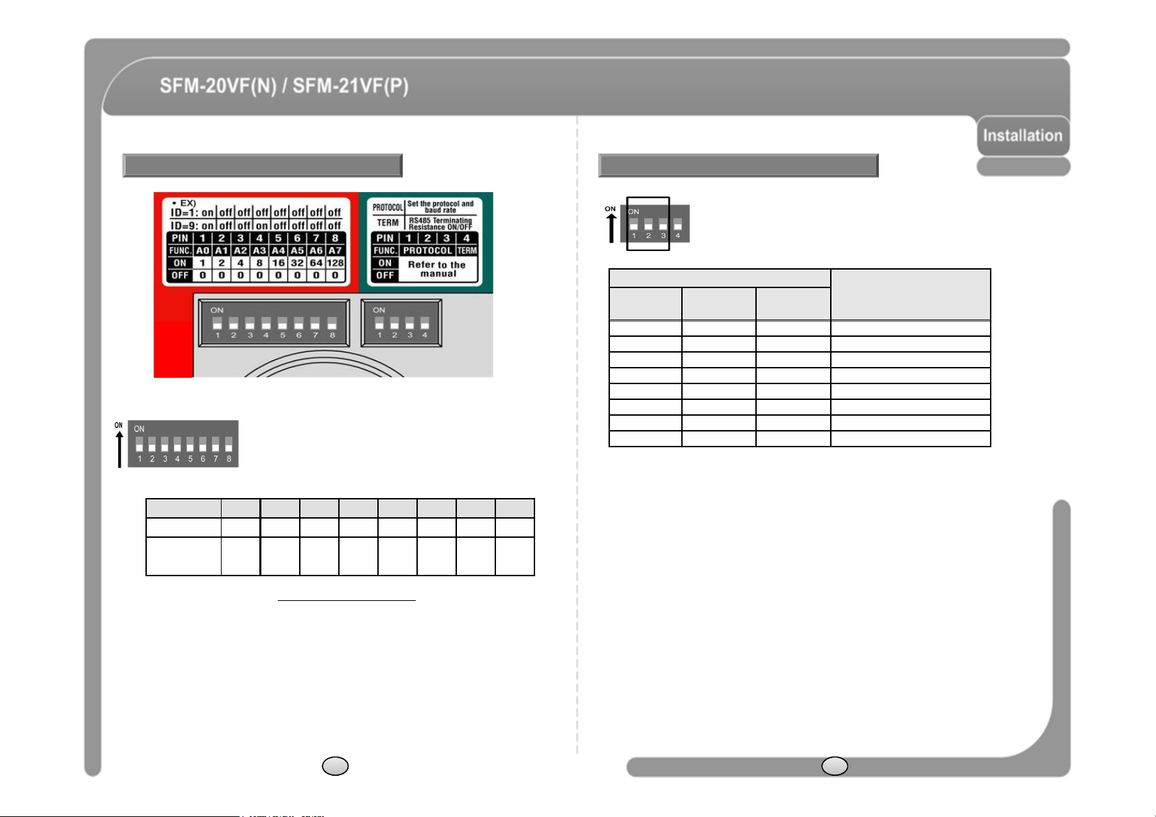
Camera ID Setup
◎ ID number of camera is set using dip switch. The example
is shown bellow.
Pin 1 2 3 4 5 6 7 8
ID Value 1 2 4 8 16 32 64 128
ex) ID=5 on off on off off off off off
ex) ID=10 off on off on off off off off
◎ The range of ID is 1~255. Do not use 0 as camera ID
Camera ID is 1.
◎ If you want to control a certain camera, you must match the camera ID with Cam
ID setting of DVR or Controller.
. Factory default of
Communication Protocol Setup
◎ Select the appropriate Protocol with DIP switch combination.
Switch State
P0
(Pin 1)
P1
(Pin 2)
P2
(Pin 3)
OFF OFF OFF PELCO-D, 2400 bps
ON OFF OFF PELCO-D, 9600 bps
OFF ON OFF PELCO-P, 4800 bps
ON ON OFF PELCO-P, 9600 bps
OFF OFF ON SAMS.. , 4800 bps
OFF ON ON Bosch , 9600 bps
ON ON ON SAMS.TW, 9600 bps
◎ If you want to control using DVR or P/T controller, their protocol must be identical to
camera. Otherwise, you can not control the camera.
◎ If you changed camera protocol by changing DIP S/W, the change will be effective
after you reboot the camera.
◎ Factory default of protocol is “Pelco-D, 2400 bps”.
◎ If you want to information using protocol setup, download is possible form CNB home
page.
- DOWNLOAD http://www.cnbtec.com/en/html/down/data_down.php
Protocol
10 11
Page 8
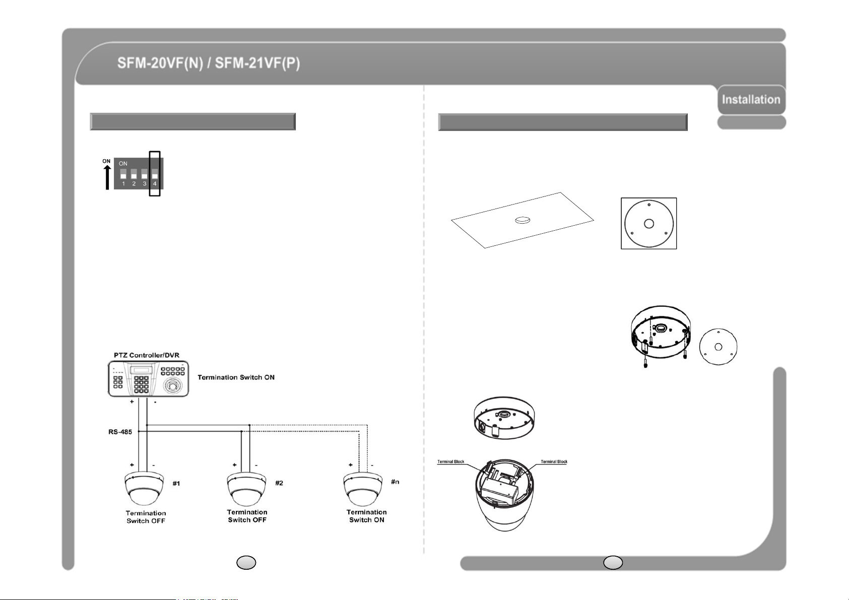
Termination Switch Setting
-
The camera may not operate correctly if multiple cameras are connected and
SFM-2XVF Installation
◎ Termination switch (Pin 4) is used in cases listed below.
◎ Long-distance communication between the controller and the camera
(1-to-1 connection)
- When the connecting distance between the two units is especially long,
communication errors may occur due to the impedance of transmission cable. In
this case, set the termination switch of both units to ON.
◎ Controlling multiple cameras (Multiple connection)
controlled. In this case, set the termination switch of the controller and the last
connected camera to ON and the switch of other cameras is OFF.
◎ This model should start to be installed under the condition which
peeling the dome cover.
① To pass cables to upside of ceiling, please, make about 50~60mm hole on the
ceiling panel.
You can use “Guide Pattern” for the making holes.
② Detach the marked part from the rubber gasket
and screw the surface mount bracket to the
ceiling with fixing screw.
③ Wire cables to terminal block and connect
the terminal blocks to main unit.
12 13
Page 9
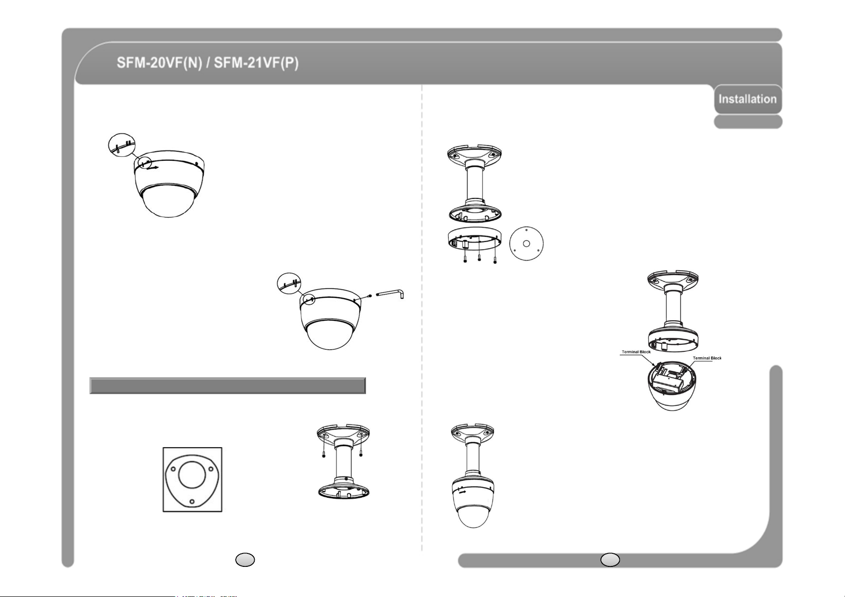
④ Insert the main body into the surface mount
terminal blocks to main unit.
bracket with the molding lines on each part being
aligned and turning clockwise.
② Detach the marked part from the rubber
gasket and screw the mounting base to
the pendant mount bracket with fixing
screws.
⑤ Insert the fixing screw tightly and detach
the protection vinyl from dome cover.
Installation using Pendant Mount Bracket
◎ This model should start to be installed under the condition which
peeling the dome cover.
① Screw pendant mount to ceiling with screws.
You can use “Guide Pattern” for the making holes.
14 15
③ Wire cables to terminal block and connect the
④ Insert the main body into the pendant mount bracket with
the molding lines on each part being aligned and turning
clockwise.
Page 10
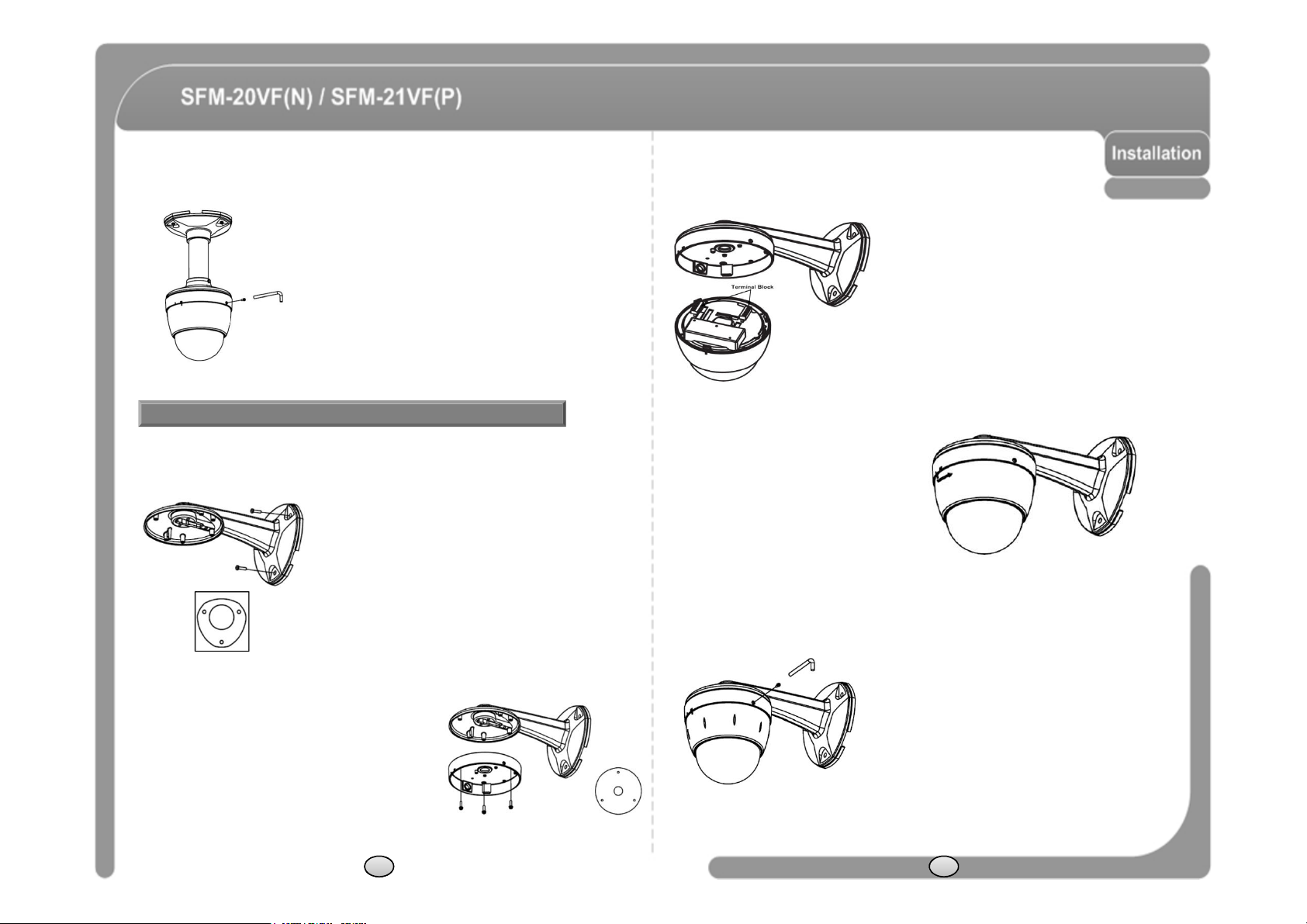
⑤ Insert the fixing screw tightly and detach the
④
Insert the main body into the wall
protection vinyl from dome cover.
Installation using Wall Mount Bracket
◎ The variable focus lens model should start to be installed under the
condition which peeling the dome cover.
① Screw all mount bracket to wall with 3 screws.
You can use “Guide Pattern" for the making holes.
③ Wire cables to terminal block and
connect the terminal blocks to main
unit.
mount bracket with the molding lines
on each part being aligned and
turning clockwise.
② Detach the marked part from the rubber gasket and
screw the mounting base to the wall mount bracket
with fixing screws.
⑤ Insert the fixing screw tightly and detach the
protection vinyl frome dome cover.
16 17
Page 11
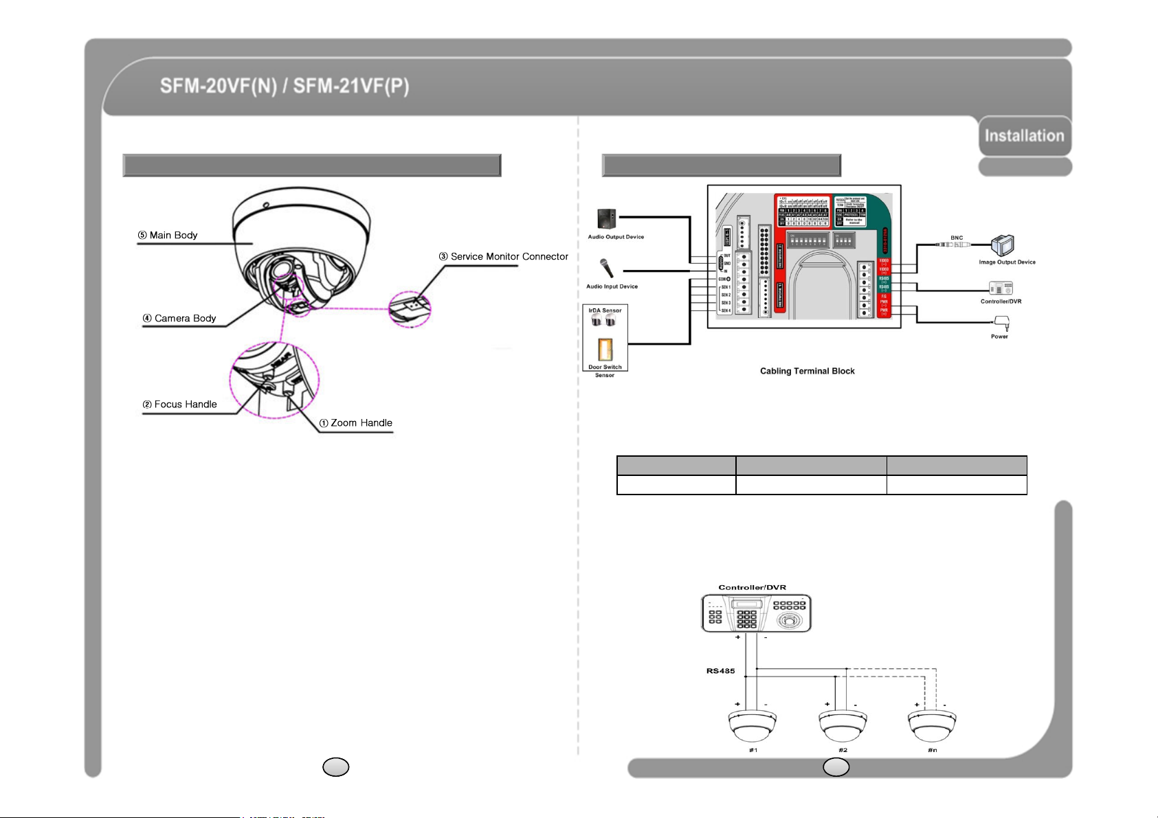
Installation of Variable Focus Lens Model Cabling
◎
Power
Connection
◎
Power
Connection
- Please, check the voltage and current capacity of rated power carefully. Rated power
① The extra video cable which is enclosed in the product connect to service monitor
connector(3).
② Confirms an image and move the camera body(4) on photographing position by
the hand. Because the camera tends not to be fixed when being installed, hold it
by the hand during the adjustment process.
③ Turn focus handle(2) and zoom handle(1) move to right and left. Adjust the image
size and focus position. After adjusting, focus handle(2) and zoom handle(1) are
tighten with driver. Not being tighten position of focus lens and zoom lens could be
shaken and move to wrong direction while control the camera.
④ After the adjustment process ends turns the dome cover to clockwise direction and
affixes. This time, the dome cover protection vinyl should be not detached. If it
does the dome cover could be damaged due to scratches and dust etc.
⑤ Turn main body(5) with a counterclockwise direction and separate it from the each
mount type. After separating terminal block which is connected to the power cable
from main body, then connect them to each other again and supply power. In
other method, After completing a whole installation process, process the SYSTEM
REBOOT in SYSTEM INITIALIZE of menu item. Otherwise camera position will
come to be mismatched while control the camera.
⑥ Turn main body(5) to clockwise direction and mount it.
⑦ Perform the next process of each mount type.
18 19
is indicated in the back of main unit.
Rated Power Input Voltage Range Current Consumption
DC 12V DC 11V ~ 18V 1 A
◎ RS-485 Communication
- For PTZ control, connect this line to keyboard and DVR. To control multiple
cameras at the same time, RS-485 communication lines of them is connected
in parallel as shown below.
Page 12
◎ Audio Input/Output Connection (Reserved for network model)
the sensor. Since output signal types of the sensors are divided into Open
- Connection with audio input/output device.
◎ Video Connection
- Connect with BNC coaxial cable.
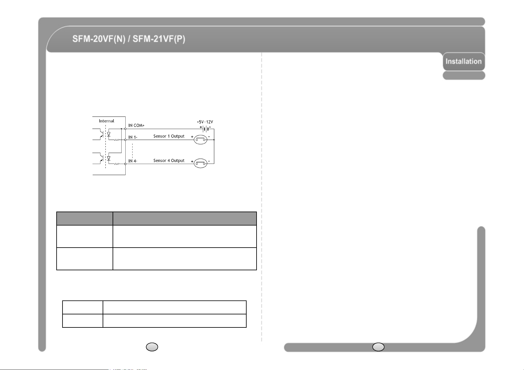
◎ Alarm Input Connection
- Sensor Input.
Before Connecting sensors, check driving voltage and output signal type of
Collector And Voltage Output type in general, the cabling must be done
properly after considering these typed.
Signal Description
IN COM+
IN1-, IN2-, IN3-, IN4-
If you want to use Alarm Input, the types of sensor must be selected in OSD
menu. The sensor types are Normal Open and Normal. If sensor type is not
selected properly, the alarm can be activated reversely.
Normal Open Output Voltage is high state when sensor is activated.
Normal Close Output Voltage is high state when sensor is not activated.
Connect (+) cable of electric power source for Sensors to
this port as shown in the circuit above.
Connect output of sensors for each port as shown in the
circuit above.
20 21
Page 13

Check Points before Operation
Alarm
Input
function
canbeconfigured
for
each
Preset and Pattern Function Pre
-
Check
◎ Before power is applied, please check the cables carefully.
◎ The camera ID of the controller must be identical to that of the target camera.
The camera ID can be checked by reading DIP switch of the camera.
◎ If your controller supports multi-protocols, the protocol must be changed to
match to that of the camera.
◎ If you changed camera protocol by changing DIP switch, the change will be
effective after you reboot the camera.
◎ Since the operation method can be different for each controller available, refer
to the manual for your controller if camera can not be controlled properly.
The operation of this manual is based on the standard Pelco®Controller.
◎ Function
Protocol
Function
Preset 127 127 127 64/127 98 127
Pattern 4 4 3 4 2 4
Swing 8 8 4 1 1 3
Group 8 8 4 1 1 6
☞ If you want to information using protocol setup, download is possible form CNB
home page.
- DOWNLOAD http://www.cnbtec.com/en/html/down/data_down.php
Pelco-D Pelco-P SAMS.. PANA.. BOSCH
SAMS.
TW
Starting OSD Menu
◎ Function Using the OSD menu, Preset, Pattern, Swing, Group and
◎ Check how to operate preset and pattern function with controller or DVR in
advance to operate camera function fully when using controller or DVR.
◎ Refer to the following table when using standard Pelco® protocol
controller.
<Go Preset> Input [Preset Number] and press [Preset] button shortly.
<Set Preset> Input [Preset Number] and press [Preset] button for more than 2
<Run Pattern> Input [Pattern Number] and press [Pattern] button shortly.
<Set Pattern> Input [Pattern Number] and press [Pattern] button for more than
◎ If controller or DVR has no pattern button or function, use shortcut keys
with preset numbers. For more information, refer to “Reserved Preset” in
this manual.
seconds.
2seconds.
22
application.
◎ Enter Menu <Go Preset> [95]
◎ Control Key OSD menu controls of all protocols use Near(Set/Select)/
Far(Cancel) key.
Reserved Preset
◎ Description Some Preset numbers are reserved to special functions.
◎ Function <Go Preset> [95] Enters into OSD menu.
(Only, support Pelco Protocols)
<Go Preset> [131~134] Runs Pattern Function 1 ~ 4.
<Go Preset> [141~148] Runs Swing Function 1 ~ 8.
<Go Preset> [151~158] Runs Group Function 1 ~ 8.
23
Page 14
PRESET
SWING
◎ Function Max. 127 positions can be stored as Preset position. The Preset
number can be assigned from 1 to 128, but 95 is reserved for starting
OSD menu.
Camera characteristics (i.e. White Balance, Auto Exposure) can be set
up independently for each preset. Label should be blank and "Camera
Adjust" should be set to "GLOBAL" as default. All characteristics can
be set up in OSD menu.
◎ Set Preset <Set Preset> [1~128]
◎ Run Preset <Go Preset> [1~128]
◎ Delete Preset To delete Preset, use OSD menu.
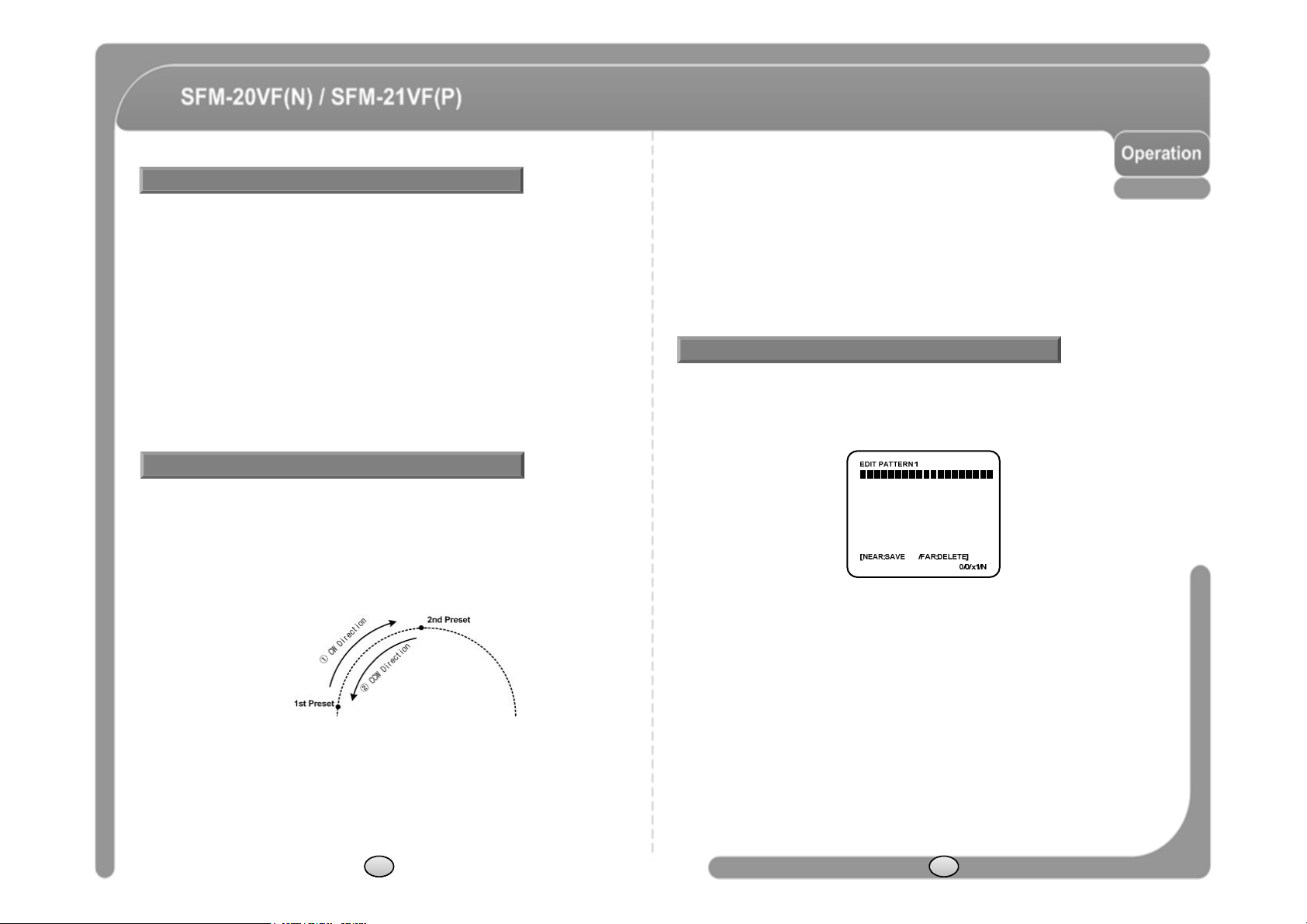
◎ Function By using Swing function, you can make camera to move between 2
Preset positions repeatedly. When swing function runs, camera moves
from the preset assigned as the 1st point to the preset assigned as the
2nd point in CW(Clockwise) direction. Then camera moves from the
preset assigned as the 2nd point to the preset assigned as the 1st point in
CCW(Counterclockwise) direction.
In case that the preset assigned as the 1st point is same as the preset
assigned as the 2nd point, camera turns on its axis by 360° in CW
(Clockwise) direction and then it turns on its axis by 360° in CCW
(Counterclockwise) direction. Speed can be set up from 1°/sec to
180°/sec.
◎ Set Swing To set Swing, use OSD menu.
◎ Run Swing Method 1) <Run Pattern> [Swing NO.+10]
Method 2) <Go Preset> [Swing NO + 140]
ex) Run Swing 3 : <Run Pattern> [13]
ex) Run Swing 3 : <Go Preset>[143]
◎ Delete Swing To delete Swing, use OSD menu.
PATTERN
◎ Function : Pattern Function is that a camera memorizes the path (mostly curve path)
by joystick of controller for assigned time and revives the path exactly as it
memorized. 4 Patterns are available and Maximum 1200 communication
commands can be stored in a pattern.
◎ Setting : Pattern can be created by one of following two methods.
Method 1) <Set Pattern> [Pattern NO.]
- Pattern editing screen is displayed as bellow.
- Movement by Joystick and preset movement
can be memorized in a pattern.
- The rest memory size is displayed in progress bar.
- To save the recording, press NEAR key and to
cancel, press FAR key.
Method 2) OSD using OSD menu: See the section “How to use OSD menu”.
◎ Run : Method 1) Run Pattern [Pattern NO.] ex) Run Pattern 2 : Run Pattern [2]
Method 2) Go Preset [Preset NO.+130] ex) Run Pattern 2 : Go Preset [132]
◎ Delete : To delete Pattern, use OSD menu.
24 25
Page 15
GROUP
◎
Alarm
Input
4
Alarm
Inputs
are
used.Ifanexternal
sensor
is
activated,
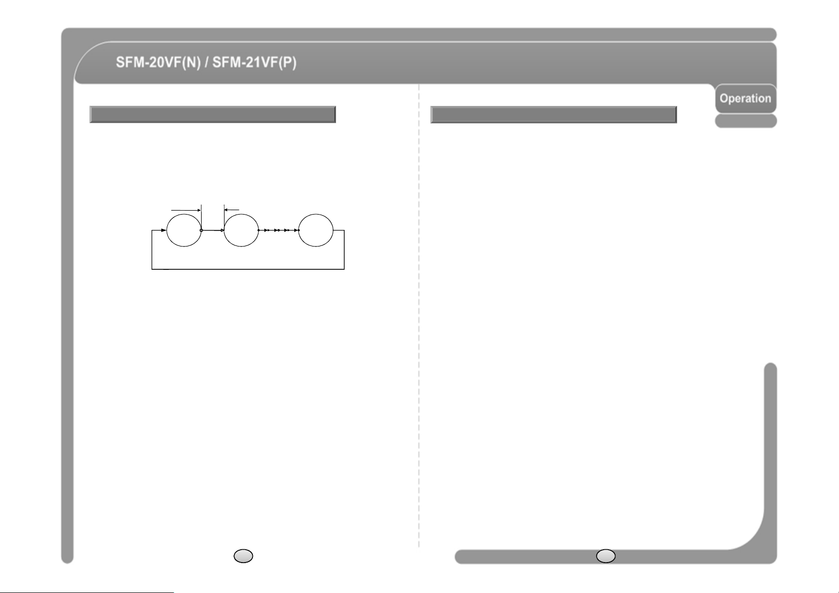
◎ Function : The group function allows running sequence of Presets, Pattern and/or
Swings. Max 8 group can be stored. Each group can have max 20 action
entities which can be preset, pattern or swing. Preset speed can be set up
and the repeat number of Pattern & Swing can be set up in Group setup.
Dwell time between actions can be set up also.
DWELL TIME
Preset 1 Pattern 1 Swing 1
Max. 20 Action
◎ Set : Use OSD menu to create a Group.
◎ Run : Method 1) Run Pattern [Group NO.+20] ex) Run Group 7 : Run Pattern [27]
Method 2) Go Preset [Group NO.+150] ex) Run Group 7 : Go Preset [157]
◎ Delete : To delete Group, use OSD menu.
Other Functions
◎ Power Up Action
◎ Auto Flip
◎ Parking Action
This function enables to resume the last action executed before
power down. Most of actions such as Preset, Pattern, Swing and
Group are available for this function but Jog actions are not
available to resume.
In case that tilt angle arrives at the top of tilt orbit(90°), the
camera pans 180°to keep tracing targets. If this function is
OFF, tilt movement range is 0 ~ 95°.
This function enables to locate the camera to specific position
automatically if operator doesn’t operate the controller for a
while. The Park Time can be defined as an interval from 1
minute to 4 hours.
camera can be set to move to corresponding preset position.
It is noted that the latest alarm input is effective if multiple
sensors are activated.
◎ GLOBAL/LOCAL
Image Setup
WB(White Balance) and AE(Auto Exposure) can be set up
independently for each preset. There are 2 modes, "Global"
mode & "Local" mode. The Global mode means that WB or AE
can be set up totally and simultaneously for all presets in "ZOOM
CAMERA SETUP" menu. The Local mode means that WB or AE
can be set up independently or separately for each preset in
each preset setup menu. Each Local WB/AE value should
activate correspondingly when camera arrives at each preset
location.
During jog operation, Global WB/AE value should be applied. All
Local WB/AE value do not change although Global WB/AE value
changes.
26 27
Page 16

OSD Display of Main Screen
◎
Camera
ID
Current
Camera
ID
(Address)
.
◎
Camera
ID
Current
Camera
ID
(Address)
.
General Rules of Key Operation for Menu
Iris Information
Camera ID
◎ P/T/Z Information
◎ Action Title
◎ IRIS Information
◎ Preset Label
◎ Alarm Input
LABEL12345
IRIS 12
CAM 1
CAM 1 15/4/x1/N
PRESET
I : 1 - - -
Action TitlePreset Label
Alarm Information
P/T/Z Information
Current Pan/Tilt angle in degree, zoom magnification and a
compass direction.
Followings are possible Action Titles and their meaning.
"SET PRESET ×××" When Preset ××× is stored.
"PRESET ×××" When camera reach to Preset ×××.
"PATTERN ×" When Pattern × is in action.
"SWG×/PRESET ×××" When Swing × is in action.
"UNDEFINED"
"IRIS 12"
When undefined function is called to run.
When IRIS Open/Close is in action.
The Label stored for specific Preset.
This information shows current state of Alarm Input. If an Input
point is ON state it will show a number corresponding to each
point. If an Input point is OFF state, '-' will be displayed.
Ex) Point 2 & 3 of inputs are ON, OSD will show as below.
I:-23-
◎ The menu items surrounded with ( ) always has its sub menu.
◎ For all menu level, to go into sub menu, press NEAR key.
◎ To go to up-one-level menu, press FAR key.
◎ To move from items to item in the menu, use joystick in the UP/DOWN or LEFT/RGHT.
◎ To change a value of an item, use UP/DOWN of the joystick in the controller.
◎ Press NEAR key to save values and Press FAR key to cancel values.
MAIN MENU
◎ SYSTEM INFORMATION
- Displays system information and configuration.
◎ DISPLAY SETUP
- Enable/Disable of OSD display on Main Screen.
◎ DOME CAMERA SETUP
- Configure various functions of this camera.
◎ SYSTEM INITIALIZE
- Initializes system configuration and sets all data to
factory default configuration.
DISPLAY SETUP
◎ This menu defines Enable/Disable of OSD display
on Main Screen. If an item is set to be AUTO, the item
is displayed only when the value of it is changed.
• CAMERA ID
• PTZ INFORMATION
• ACTION TITLE
• PRESET LABEL
• ALARM INPUT
[ON/OFF]
[ON/OFF/AUTO]
[ON/OFF/AUTO]
[ON/OFF/AUTO]
[ON/OFF/AUTO]
28 29
Page 17

Compass Direction Setup
AUTO EXPOSURE Setup
◎ Set North to assign compass direction as criteria.
Move camera and press NEAR button to save.
CAMERA SETUP
◎ GAMMA [CRT1/CRT2/LCD1/LCD2]
- Monitor Gamma Gain setup
◎ AUTO EXPOSURE SETUP
- Day/Night, AGC, Shutter, SBLC Setup… etc.
◎ WHITE BALANCE SETUP
- WB, Color Gain setup
WHITE BALANCE SETUP
◎ WB MODE [AUTO/MANUAL]
- In Manual mode, Red and Blue level can be set
up manually.
◎ RED ADJUST [1~160]
◎ BLUE ADJUST [1~160]
◎ COLOR GAIN
- Red and Blue level can be set up manually
- R-Y [1~20]
- B-Y [1~20]
◎ DAY/NIGHT [AUTO(0~20/LOW~HIGH)/COLOR/BW(Burst)]
- From BW with AUTO undergoes an
influence at the time of “Delay Time” set.
“D&N LEVEL” mode controls a Day/Night
level. COLOR mode is Day, BW mode is
Night will be able to control Burst On/Off.
◎ SHARPNESS [0~20]
- Adjust SHARPNESS of the image.
◎ SBLC [OFF/LOW/MIDDLE/HIGH]
- Sets Backlight Compensation to ON/OFF.
◎ DNR [OFF/LOW/MIDDLE/HIGH]
- Enhances images by deducting noises when gain level of images is too high.
◎ AGC [ON(0~20)/OFF]
- Enhances image brightness in case that luminance level of image signal is too low.
◎ LENS LEVEL [OFF/NORMAL/HIGH]
- Iris should be fixed and Iris has lower
priority in adjusting AE, in comparison with
others.
◎ FLICKERLESS [ON/OFF]
- Sets Flickerless function to ON/OFF.
- If Flickerless is set to ON, Shutter Speed
does not become regulation.
◎ SHUTTER [---/Manual(1/60sec~1/120000sec)]
- Shutter Speed should be set to 1/120 sec for NTSC and 1/100 for PAL.
NOTE1) Relationship of function setup
FLICKERLESS SHUTTER
ON
OFF
If FLICKERLESS mode is turned ON, SHUTTER mode is fixed default value.
Not Active
Active
30 31
Page 18

MOTION SETUP
command
during
assigned
"Wait
Time"
.
PARKING ACTION SETUP
◎ Setup the general functions of Pan/Tilt motions.
• MOTION LOCK [ON/OFF]
- If Motion Lock is set to ON, it is impossible to set up
and delete Preset, Swing, Pattern and Group. It is
possible only to run those functions. To set up and
delete those functions, enter into OSD menu.
• PWR UP ACTION [ON/OFF]
- Refer to “Other Functions" section.
• AUTO FLIP [ON/OFF]
- Refer to “Other Functions" section.
• JOG MAX SPEED [1°/sec ~360°/sec]
- Sets maximum jog speed. Jog speed is inversely
proportional to zoom magnification. As zoom
magnification goes up, pan/tilt speed goes down.
• JOG DIRECTION [INVERSE/NORMAL]
- If you set this to ‘Inverse’, the view in the screen is
moving same direction with jog tilting. If ‘Normal’ is
selected, the view in the screen is moving reversely.
• TILT ANGLE [ON/OFF]
- If “TILT ANGLE” function is “ON”, Tilt start position is
5 degree.
◎ If Park Enable is set to ON, camera runs assigned
function automatically if there is no PTZ command
during assigned "Wait Time".
• PARK ENABLE [ON/OFF]
• WAIT TIME [1 minute ~ 4 hour]
- The time is displayed with "hh:mm:ss" format and
you can change this by 1 min unit.
• PARK ACTION
[HOME/PRESET/PATTERN/SWING/GROUP]
- HOME
Camera moves to home position if there is no PTZ
ALARM INPUT SETUP
◎ Match the Alarm sensor input to one of Preset
positions. If an external sensor is activated,
camera will move to corresponding preset position
when this item is predefined.
• ALARMx TYPE
[Normal OPEN/Normal CLOSE]
- Sets sensor input type.
• ALARMx ACT
[NOT USED/PRESET 1~128]
- Assign counteraction Preset position to each
Alarm input.
32 33
Page 19

PRESET SETUP
◎
EDIT LABEL
①
Edits
labeltoshowonmonitor
when
camera
EDIT PRESET SCENE
◎ PRESET NO [1~128]
- If a selected preset is already defined, camera
moves to pre-defined position and preset
characteristics such as Label and Relay Outputs
show on monitor. If a selected preset is not defined,
“UNDEFINED” shows on monitor.
◎ CLR PRESET [CANCEL/OK]
- Delete current Preset data.
◎ EDIT SCENE
- Redefine current Preset scene position (i.e. PTZ).
- Edits Label to show on monitor when preset runs. MAX. 10 alphabets are allowed.
◎ CAM ADJUST [GLOBAL/LOCAL]
- WB(White Balance) and AE(Auto Exposure) can be set up independently for each
preset. There are 2 modes, "Global" mode & "Local" mode. The Global mode means
that WB or AE can be set up totally and simultaneously for all presets in "CAMERA
SETUP" menu.
The Local mode means that WB or AE can be set up independently or separately for
each preset in each preset setup menu. Each Local WB/AE value should activate
correspondingly when camera arrives at each preset location. During jog operation,
Global WB/AE value should be applied.
All Local WB/AE value should not change although Global WB/AE value changes. If
“Local’’ is selected, Menu to set WB/AE shows on monitor.
① Using Joystick, move camera to desired
position.
② By pressing NEAR key, save current PTZ
data.
③ Press FAR key to cancel.
EDIT PRESET LABEL
arrives at presets. In Edit Label menu, a reverse
rectangular is cursor. As soon as finishing
selecting alphabet, cursor moves to the next
digit.
② Using LEFT/RIGHT/UP/DOWN of joystick, move
to an appropriate character from the Character
set. To choose that character, press the NEAR
key. If you want to use blank, choose Space
character (" "). If you want to delete a character
before, use back space character (" ←").
③ If you complete the Label editing, move cursor to
"OK" and press NEAR key to save completed
label. To abort current change, move cursor to
"Cancel" and press NEAR key.
34 35
Page 20

SWING SETUP
SWING NO
.
1
PATTERN SETUP
◎ SWING NO
◎ 1ST POS.
◎ 2ND POS.
SWING SETUP
1ST POS .
☞
2ND POS .
When swing function runs, camera moves from the preset
assigned as the 1st point to the preset assigned as the 2nd point
in CW(Clockwise) direction. Then camera moves from the preset
assigned as the 2nd point to the preset assigned as the 1st point
in CCW(Counterclockwise) direction. In case that the preset
assigned as the 1st point is same as the preset assigned as the
2nd point, camera turns on its axis by 360° in CW direction and
then it turns on its axis by 360° in CCW direction.
◎ SWING SPEED [1°/sec ~180°/sec]
Sets Swing speed from 1°/sec to 180°/sec.
◎ CLEAR SWING [CANCEL/OK]
Deletes current Swing data.
[1~8]
Selects Swing number to edit.
If a selected Swing has not defined,
"NOT USED" is displayed in 1st
Position and 2nd Position
[PRESET 1~128]
Set up the 2 position for Swing function.
If a selected preset is not defined,
"UNDEFINED" will be displayed as
shown below.
PRESET 5
NOT USED
UNDEFINED
◎ PATTERN NO
[1~4 ]
Selects Pattern number to edit.
If a selected pattern number is
not defined, "UNDEFINED" will
be displayed under selected
pattern number.
◎ CLR PATTERN
[CANCEL/OK]
Deletes data in current pattern
◎ EDIT PATTERN
Starts editing pattern.
EDIT PATTERN
NEAR
◎ By using Joystick, move to start position with appropriate zoom. To start pattern
recording, press NEAR key. To exit this menu, press FAR key.
◎ Move camera with joystick of controller or run preset function to memorize the path
(mostly curve path) in a selected pattern. The total memory size and the rest memory
size is displayed in the form of bar. Maximum 1200 communication commands can be
stored in a pattern.
◎ To save data and exit, press NEAR key. To cancel recording and delete record data,
press FAR key.
36 37
Page 21

GROUP SETUP
◎
ACTION ###
[NONE/PRESET/SWING/PATTERN]
EDIT GROUP
◎ GROUP NO
◎ CLEAR GROUP
◎ EDIT GROUP
◎ DWELL [0 sec~4minutes]
- Sets Dwell Time between functions.
◎ OPT
- Option. It should be preset speed when preset is
set in Action. It should be the number of repeat
when Pattern or Swing is selected in Action.
[1~8]
Selects Group number to edit.
If a selected Group number is
not defined, "UNDEFINED" will be
displayed under selected Group
number.
[CANCEL/OK]
Deletes data in current Group
Starts editing Group.
NEAR
◎ Set up Action, Dwell time and Option. Note that selected item is displayed in reverse.
Move cursor LEFT/RIGHT to select items and move cursor UP/DOWN to change
each value.
◎ Set up items such as Action, ###, Dwell and OPT.
◎ After finishing setting up a Action, press NEAR key to one-upper-level menu.
Move cursor UP/DOWN to select Action number and repeat.
◎ After finishing setting up all Actions, press FAR key to exit. Then cursor should be
moved to “SAVE”. Press NEAR key to save data.
◎ Press NEAR key in “NO” list to start Group setup.
◎ Note that MAX. 20 Functions are allowed in a Group. Move cursor UP/DOWN and
press NEAR key to set up.
38 39
Page 22

SYSTEM INITIALIZE
-
Deletes
Preset
Data,
Swing
Data,
Pattern
Data
and
Group
Data
.
AUTO
FLIPONWHITE
BALANCE
AUTO
Initial Configuration Table
◎ CLR MOTION SET
- Initializes Motion Configuration.
◎ CLR EDIT SET
◎ REBOOT CAMERA
- Reboots Zoom Camera module.
◎ REBOOT SYSTEM
- Reboots Speed Dome Camera.
◎ CLEAR ALL DATA
- Deletes all configuration data such as display,
camera, motion setup and so on.
◎ CLR DISPLAY SET
- Initializes Display Configuration.
◎ CLR CAMERA SET
- Initializes Camera Configuration.
Display Configuration Camera Configuration
CAMERA ID ON SHARPNESS 10
PTZ INFORMATION AUTO SBLC OFF
ACTION TITLE AUTO DNR LOW
PRESET LABEL AUTO AGC ON
ALARM INPUT AUTO AGC LEVLEL 15
NORTH DIRECTION Pan 0° GAMMA CRT2
Motion Configuration LENS LEVEL 8
MOTION LOCK OFF FLICKERLESS OFF
PWR UP ACTION ON SHUTTER 1/60
JOG MAX SPEED 120°/sec WB- RED MANUAL – 63
JOG DIRECTION INVERSE WB- BLUE MANUAL – 96
FRZ IN PRESET OFF COLOR GAIN(R-Y) 15
PARK ACTION OFF COLOR GAIN(B-Y) 15
ALARM ACTION OFF User Edit Data
DAY/NIGHT AUTO PRESET 1~128 UNDEFINED
DELAY TIME 3 SWING 1~8 UNDEFINED
D/N LEVEL MIDDLE PATTERN 1~4 UNDEFINED
BURST ON GROUP 1~8 UNDEFINED
40 41
Page 23

Specifications
DNR
High / Middle / Low / Off
DNR
High / Middle / Low / Off
Model SFM-20VF(N)/SFM-21VF(P)
Video Signal System NTSC PAL
CCD 1/3'' Interline CCD
Effective Pixels 768(H)×494(V) 752(H)×582(V)
Video Output 1.0Vp-p / 75 ohm Video 0.714Vp-p Sync 0.286Vp-p
Horizontal Res. 600 TV Line(Color), 650 TV Line(B/W)
S/N Ratio 50 dB (AGC Off)
Lens Variable focus lens (f=3.8mm ~ 9.5mm)
Min. illumination 0.1 Lux (Color) / 0. 03 Lux (B/W)
Day & Night (Auto) / Color / (B/W)
Camera
Pan/Tilt
General
* Specifications of this product can be subjected to change without notice.
** Check the voltage and current capacity of rated power carefully.
Iris DC Lens Levels
Flickerless(FLK) On / Off
Shutter Speed FLK : On(1/60 ~ 1/120000 sec)/Off(x)
White Balance Auto / Manual(Red, Blue Gain Adjustable)
Color Gain R-Y(1~20) / B-Y(1~20)
Sharpness 0~20
SBLC High / Middle / Low / Off
AGC On(0~20) / Off
Range
Pan/Tilt Speed
Preset 127 Preset (Label, Camera Image Setting)
Pattern 4 Pattern, 1200 commands(about 5 minute)/Pattern
Swing 8 Swing
Group 8 Group (20 action entities per Group)
Other Functions Auto Flip, Auto Parking, Power Up Action etc.
Communication RS-485
Protocol
Alarm Input 4 Input
OSD Menu / PTZ information etc
Rated Power** DC 12V / 1.0A
Dimension
Weight about 1 Kg
Operating Temp. 0°C ~ 40°C (32°F ~ 104°F)
Pan : 360°(Endless)
Tilt : 180° (Auto-Flip), 90° (Normal)
Preset : 360°/sec
Manual : 0.05 ~ 360°/sec
Swing : 1~ 180°/sec
Pelco-D, Pelco-P, SAMS E/TW, BOSCH,
PANAS old/new selectable
Dome : ∅115
Housing : ∅147.5 × 141(H) mm
Dimension
Main Unit
Pendant Mount
Wall Mount
42 43
Page 24

Dimension
Unit (mm)
Main Unit & Surface Mount Bracket Ceiling Mount Bracket
Wall Mount Bracket
44 45
Page 25

Mini PTZ Dome Vari-focal Camera SFM-2xVF(N/P)
설치 및 사용 메뉴얼 Ver 1.1 (3810-0215B)
Page 26

경 고
않은높은전압으로부터의
위험성을
사용자에게
경고하는
표시
이 표시는 사람에게 전기적 충격으로 인한 위험성이 충분히 있는
높은 전압이 제품 내부에서 나타나게 됨으로써 이러한 절연되지
입니다.
이 표시는 제품을 동작시키거나 정비(보수)를 함에 있어서 중요한
내용임을 사용자에게 주지 시키는 표시입니다.
주의 사항
안전에 대한 사항
◎ 사용하시기 전에 안전에 대한 사항 및 본 제품의 조작 방법을 잘 읽어 주십시오.
◎ 제품의 올바른 사용을 위해서 사용설명서는 잘 보관하십시오.
◎ 기기의 제조사로부터 추천되지 않은 부착물은 위험을 초래할 수 있으므로 사용하지
마십시오.
◎ 물이나 습기가 많은 환경에서는 본 제품을 사용하지 마십시오.
◎ 불안정한 상태로 설치하거나 불안정한 곳에 제품을 올려두지 마십시오.
제품을 떨어뜨리면 사람에게 중대한 상패를 입히거나 제품에 큰 손상을 초래합니다.
제품과 함께 판매되거나 제조사로부터 추천된 고정장치를 사용하십시오. 제품 부착은
제조사의 설치 방법에 따라 하여 주시고 반드시 제조사로부터 추천된 부품을 사용하여
주십시오.
◎ 본 제품은 정격 전원의 형식에 대해서만 동작됩니다.
사용시 주의사항
◎ 사용하시기 전에 결선과 전원연결이 올바른지 확인하십시오
◎ 사용하는 동안 어떠한 비정상적인 상태 또는 이상 동작이 관측될 경우 사용을 중지하고
즉시 공급자에게 문의하십시오.
◎ 제품을 분해하지 마시고 제품 내부의 부품을 만지지 않도록 주의하십시오.
◎ 제품의 손상을 피하기 위하여 카메라를 떨어뜨리거나 진동 및 충격을 가하지 마십시오.
◎ 커버를 청소할 때에는 커버에 이물질이 묻거나 흠집이 나지 않도록 주의하십시오.
◎ 허용되는 온도 범위를 초과하는 곳에 카메라를 설치하지 마십시오.
◎ 습기 또는 먼지가 많은 곳에서의 설치는 피해주십시오.
◎ 방사능이 있는 곳에서의 설치는 피해 주십시오. 부품에 고장을 일으킬 수 있습니다.
◎ 강한 자기장이나 전기 신호가 있는 곳에서의 설치는 피해 주십시오.
◎ 강한 진동이 가해지는 곳에서의 설치는 피해 주십시오.
◎ 카메라를 비 또는 물에 절대로 노출 시키지 마십시오.
Page 27

제품 특징
스윙
-------------------------------------------------------------------------------------------------------
70
시스템
초기화
--------------------------------------------------------------------------------------
86
제품 구성품
설치
운전
설치 확인 ------------------------------------------------------------------------------------------------
Preset 및 Pattern 기능 확인 ------------------------------------------------------------------------
OSD 메뉴 선택 ----------------------------------------------------------------------------------------
특수기능의 프리셋 ------------------------------------------------------------------------------------
프리셋 ----------------------------------------------------------------------------------------------------
--------------------------------------------------- 52
--------------------------------------------------- 54
--------------------------------------------------- 55
--------------------------------------------------- 68
68
68
69
69
70
OSD 메뉴 기능
메뉴 사용법 -----------------------------------------------------------------------------------------
메인 메뉴 --------------------------------------------------------------------------------------------
주 화면 OSD 표시 설정 --------------------------------------------------------------------------
방위 위치 설정 -------------------------------------------------------------------------------------
카메라 모듈 설정 -----------------------------------------------------------------------------------
모션 설정 --------------------------------------------------------------------------------------------
프리셋 설정 -----------------------------------------------------------------------------------------
스윙 설정 ---------------------------------------------------------------------------------------------
패턴 설정 --------------------------------------------------------------------------------------------
그룹 설정 --------------------------------------------------------------------------------------------
------------------------------------------------ 75
75
75
75
76
76
77
80
82
83
84
패턴 -------------------------------------------------------------------------------------------------------
그룹 -------------------------------------------------------------------------------------------------------
기타 주요 기능 -----------------------------------------------------------------------------------------
주 화면 OSD 구성 -------------------------------------------------------------------------------------
71
72
73
74
제품사양
------------------------------------------------ 88
Page 28

카메라 영상부 사양
◎ 1/3” Interline Transfer CCD.
◎ 렌즈 : 가변초점렌즈(3.8mm~9.5mm) 사이즈 : 42x42mm.
◎ Day & Night 기능.
◎ WHITE BALANCE, SHUTTER, AGC, SBLC 등, OSD 메뉴를 이용하여 영상부의 미세한
설정을 수행할 수 있습니다.
강력한 팬/틸트 기능
◎ 프리셋 운전시 최대 360°/초의 고속 운전이 가능합니다.
◎ 프리셋 운전시 팬과 틸트가 동시에 보간 운전되므로 빠르고 자연스러운 화면 확인
이 가능합니다.
◎ 조그 운전시 0.05°/초의 저속 운전이 가능하여 원하는 위치로 보다 정밀하게 이동
할 수 있습니다. 또한, 원하는 위치로 쉽게 이동할 수 있습니다.
프리셋, 패턴, 스윙, 그룹 기능
◎ 127개의 프리셋 위치를 지정할 수 있으며, 프리셋 마다 카메라 영상 설정을 독립적
으로 지정할 수 있습니다. 이외에도 프리셋 위치에 따른 레이블, 디지털 출력을 설정
할 수 있습니다.
◎ 2개의 프리셋 위치를 반복적으로 이동하는 스윙 기능이 지원합니다.(8 스윙)
◎ 일정 시간 동안 조그 운전을 그대로 저장하여 다시 실행하는 패턴기능이 지원됩니
다. (4 패턴)
◎ 프리셋/패턴/스윙을 조합한 20개의 동작을 순차적으로 수행하는 그룹기능이 지원
됩니다.(8그룹)
PTZ 제어
◎ 최대 255개까지 카메라를 동시에 연결하여 사용할 수 있습니다.
◎ 최대 전면부 10m 범위내에서 리모컨을 이용해 카메라 제어가 가능 합니다.
◎ Pelco-D, Pelco-P 프로토콜 선택이 가능합니다.
OSD(On Screen Display) 메뉴 지원
◎ OSD 메뉴를 통해 제품의 다양한 기능을 사용할 수 있습니다.
◎ 카메라 ID, 팬/틸트 위치, 방위 정보, 알람 입/출력, 프리셋 정보 등이 화면상에
표시 됩니다.
알람 입/출력 기능
◎ 4개의 센서 입력, 1개의 센서 출력을 사용할 수 있습니다.
◎ 외부의 전기적인 노이즈를 제거하기 위해 센서 입력은 포토 커플러 방식을
사용하고 있습니다.
◎ Normal Open 또는 Normal Close 방식의 센서를 모두 사용할 수 있습니다.
◎ 센서 입력은 DC 5~12V의 출력의 센서를 연결할 수 있습니다.
◎ 외부 센서의 동작에 따라 원하는 프리셋 위치로 이동할 수 있습니다.
52 53
Page 29

구성품
돔
커버가
긁히거나
이물질이
묻는경우카메라
영상에
나타날
수
있으므로
,
◎ 기본 구성품
◎ 별매품
● 천장 취부형 브라켓 ● 벽부 취부형 브라켓
각 부 명칭 및 기능
본체 및 고정 브라켓 본체 후면
◎ 돔 커버
설치가 모두 끝나기 전까지는 돔 커버 보호용 비닐을 제거하지 마십시오.
돔 커버는 클리어와 스모크 타입중 하나를 선택할 수 있습니다.
◎ 고정 브라켓
카메라를 천장에 직접 설치할 때 사용합니다. 본체에서 고정 브라켓 분리하고
이를 먼저 설치한 후, 본체를 장착하십시오. 벽부 취부형 브라켓이나 천장 취
부형 브라켓을 사용할 때에는 사용하지 마십시오.
◎ 고정 나사
본체를 고정 브라켓에 고정합니다.
◎ 결선용 터미널
카메라에 전원, 영상 신호, 통신 신호, 센서신호를 결선합니다.
◎ 딥 스위치
카메라 ID와 통신 프로토콜등을 설정합니다.
◎ 포커스 조절 레버
촬상 대상의 초점을 맞춥니다.
◎ 줌 조절 레버
촬상 대상의 크기를 조절합니다.
◎ 비디오 출력 단자
카메라 설치 시 영상출력을 확인합니다.
54 55
Page 30

DIP 스위치
카메라
ID
설정
ON
OFFONPANA.. , 9600 bps
통신 프로토콜 설정
◎ 다음과 같이 프로토콜을 설정하십시오.
스위치 상태
P0
(Pin 1)
OFF OFF OFF PELCO-D, 2400 bps
ON OFF OFF PELCO-D, 9600 bps
OFF ON OFF PELCO-P, 4800 bps
ON ON OFF PELCO-P, 9600 bps
OFF OFF ON SAMS.. , 4800 bps
P1
(Pin 2)
P2
(Pin 3)
프로토콜
◎ 카메라의 ID를 딥 스위치의 조합으로 설정하며 각 핀의
설정값은 다음과 같습니다.
핀 1 2 3 4 5 6 7 8
설정값 1 2 4 8 16 32 64 128
ex) ID=5 on off on off off off off off
ex) ID=10 off on off on off off off off
◎ 1~255 까지 최대 255개의 ID를 설정할 수 있습니다. 0번 ID는 절대 사용하지
마십시오.
◎ 출하 시 설정 ID는 1번입니다.
◎ 키보드 제어기를 연결하여 운전할때는 DIP 스위치에서 설정한 ID와 제어기의
ID를 일치시키십시오.
56 57
OFF ON ON Bosch , 9600 bps
ON ON ON SAMS.TW, 9600 bps
◎ 키보드 제어기나 DVR 에서 사용하는 프로토콜과 일치시키십시오.
◎ 반드시 전원이 꺼진 상태에서 프로토콜을 변경하십시오.
◎ 출하 시 설정된 프로토콜은 Pelco-D, 2400 bps 입니다.
◎ 각 프로토콜에 대한 자세한 정보는 홈페이지에서 다운로드 가능합니다.
- 다운로드 http://www.cnbtec.co.kr/ko/html/down/data_down.php
Page 31

종단저항 설정
가장
마지막에
위치한
카메라
1대의종단
저항만을
ON으로설정하십시오
.
종단 저항은 다음과 같은 경우에 사용합니다.
◎ 제어기와 카메라의 통신 결선이 아주 긴 경우 (1:1 연결)
- 제어기와 카메라 사이의 거리가 아주 먼 경우 통신 선로의 임피던스 문제로 인해
통신 장애가 발생할 수 있습니다. 이 경우에 제어기와 카메라 모두 종단 저항을
ON으로 설정하여 사용하십시오.
◎ 여러 대의 카메라를 동시에 연결하여 사용할 경우
- 여러 대의 카메라를 동시에 하나의 제어기에 연결한 경우에도 통신 장애가 발생할
수 있습니다. 이 경우에는 제어기의 종단 저항을 ON으로 설정하고, 카메라 중에서
천장에 직접 설치
◎ 돔 커버를 벗긴 상태에서 설치를 시작하시기 바랍니다.
① 배선을 위해 천장에 50~60mm정도의 구멍을 뚫습니다.
천장에 구멍을 뚫으실 때, 시공지본을 사용하시면 보다 편리하게 작업할 수 있습니다
절대 모든 카메라의 종단 저항을 ON으로 설정하지 마십시오.
예제) 여러 대 카메라를 연결하여 사용할 경우
58 59
② 결선을 위해 고무 개스킷의 중앙 부근에 동그랗게
파인 부분을 뜯어내고 나사를 이용하여 고정 브라
켓을 천장에 장착하십시오.
③ 터미널 단자대를 이용하여 배선을 연결하시고
고정브라켓에 본체를 장착합니다.
Page 32

④ 본체를 화살표 방향으로 돌려 고정합니다.
커버의
보호용
비닐을
제거합니다
.
고정
브라켓에
본체를
장착합니다
.
② 결선을 위해 고무 개스킷의 중앙 부근의
동그랗게 파인부분을 뜯어내고 천장 취부
형 브라켓과 고정 브라켓을 나사를 이용하
여 장착합니다.
⑤ 고정나사를 이용하여 설치를 완료하고 돔
천장 취부형 브라켓을 이용한 설치
◎ 돔커버를 벗긴 상태에서 설치를 시작하시기 바랍니다.
① 천장에 천장 취부형 브라켓을 조립합니다.
천장에 구멍을 뚫으실 때, 시공지본을 사용하시면 보다 편리하게 작업할 수 있습니다.
60 61
③ 터미널 단자대를 이용하여 배선을 연결하시고,
④ 본체를 화살표 방향으로 돌려 고정합니다.
Page 33

⑤ 고정나사를 이용하여 설치를 완료하고 돔커버의
◎
돔커버를
벗긴
상태에서
설치를
시작하시기
바랍니다
.
◎
돔커버를
벗긴
상태에서
설치를
시작하시기
바랍니다
.
④
본체를
화살표
방향으로
돌려
고정합니다
.
보호용 비닐을 제거 합니다.
벽면 취부형 브라켓을 이용한 설치
① 벽면 취부형 브라켓을 벽면에 고정하십시요.
천장에 구멍을 뚫으실 때, 시공지본을 사용하시면 보다 편리하게 작업할 수 있습니다.
② 결선을 위해 고무 개스킷의 중앙 부근의 동그랗게
파인부분을 뜯어내고 천장 취부형 브라켓과 고정
브라켓을 나사를 이용하여 장착합니다.
③ 터미널 단자대를 이용하여 배선을
연결하시고, 고정 브라켓에 본체를
장착합니다.
⑤ 고정나사를 이용하여 설치를 완료하고 돔커버
보호용 비닐을 제거 합니다.
62 63
Page 34

가변초점렌즈모델 설치과정 결선
◎
전원
◎
전원
- 제품의 모델명을 확인하여 올바른 전원을 사용하십시오. 제품의 전원 사양은 제품
① 비디오출력단자(3)에 제품과 동봉된 여분의 비디오 케이블을 연결하십시요.
② 영상을 확인하면서 카메라 본체(4)를 손으로 촬상하고자 하는 위치로 이동합니다.
이때, 카메라가 고정되지 않으므로 다음과정을 진행할 때 카메라가 고정되도록
손으로 잡고 조정과정을 진행해야 합니다.
③ 포커스 렌즈 조정레버(2)와 줌렌즈 조정 레버(1)를 좌우로 움직여 촬상 대상의
초점 및 크기를 조정하신 후 드라이버를 이용하여 레버를 조여 렌즈의 유동이 없게
하십시요, 그렇지 않으면 카메라의 구동 중 포커스가 틀어질 수 있습니다.
④ 조정과정이 모두 끝났으므로 돔커버를 시계방향으로 돌려 장착하여 주십시요.
이때, 돔커버의 보호용 비닐이 있는 상태로 작업하시기 바랍니다. 그렇지 않으면
돔커버가 기스나 이물질에 의해 손상될 수 있습니다.
⑤ 본체(5)을 시계반대방향으로 돌려 마운트와 분리 하십시요. 전원이 연결된 터미널
단자를 본체에서 분리한 후 재결합하여 카메라에 전원을 재인가 하십시요. 혹은
전체 설치를 완료한 후에 매뉴얼의 메뉴기능 중 SYSTEM INITIALIZE 항목을 참고하
여 SYSTEM REBOOT을 1회 실행하여 주시기 바랍니다. 그렇지 않으면, 카메라 제어
시 위치 값이 틀어질 수 있습니다.
⑥ 본체(5)을 시계방향으로 돌려 마운트와 결합 하십시요.
⑦ 각 설치법의 다음과정을 진행 하십시요.
뒷면이나 매뉴얼에 표시되어 있습니다. 본 제품의 정격 전원은 다음과 같습니다.
◎ RS-485 통신
- PTZ 제어 명령을 지령하는 키보드 제어기나, DVR 등을 연결하십시오. 여러
대의 카메라를 동시에 제어 할 경우 RS-485 통신 선을 병렬로 연결하여 사용
하십시오.
정격 전원 입력 전압 허용 범위 소모 전류
DC 12V DC 11V ~ 18V 1 A
64 65
Page 35

◎ 오디오 입출력 (네트워크 모델에 한하여 적용됩니다)
- 오디오 입출력 장치를 결선하십시오.
◎ 영상 출력
- 반드시 BNC 케이블을 사용하여 결선하십시오.
◎ 센서 입력
- 센서를 결선하기 전에 센서의 구동 전압과, 센서의 신호 출력 방식을 체크하
십시오. 센서의 신호 출력방식은 크게 Open Collector 방식과 Voltage Output
방식이 있으므로, 각각의 경우에 맞게 결선하여야 합니다.
Signal Description
COM+ 입력 회로를 구동하는 전원입니다. 센서를 구동하는 전원의 (+)
극성을 연결하십시오.
SEN 1,2,3,4 센서의 출력신호를 연결하십시오.
- 센서를 사용하기 위해서는 OSD 메뉴에서 센서 타입을 설정하십시오. 센서
타입은 크게 Normal Open 과 Normal Close로 구분할 수 있습니다. 센서
입력 타입을 잘못 설정할 경우, 센서 입력에 대해 반대로 동작합니다.
Normal Open 센서가 동작할 때 전압이 출력되는 방식.
Normal Close 센서가 동작하지 않을 때 전압이 출력되는 방식.
66 67
Page 36

설치 확인
◎
기능
카메라의
OSD메뉴기능을
사용하여
영상을
설정하거나
,
Preset,
◎ 전원을 인가하기 전에 결선에 이상이 없는지 확인하여 주십시오.
◎ 운전하고자 하는 카메라의 ID를 확인하신 후 제어기에서 올바른 카메라 번호를 선택
하십시요.
◎ 카메라 ID는 화면 또는 DIP 스위치에서 확인할 수 있습니다.
◎ 제어기가 여러 가지 프로토콜을 지원하는 경우 카메라에 설정된 프로토콜과 일치시키
십시오.
◎ 카메라 프로토콜을 변경하는 경우 전원을 끈 상태에서 수행하십시오.
◎ 제어기와 관련된 기능은 제어기에 따라 사용 방법이 일부 다를 수 있으므로 정상 동작이
되지 않을 경우 제어기의 사용 방법을 참조하십시오. 본 매뉴얼상의 사용방법은 Pelco
표준 프로토콜 제어기에 기준한 것입니다.
◎ 기능
기능
프로토콜
Pelco-D Pelco-P SAMS.. PANA.. BOSCH
SAMS.
TW
Preset 127 127 127 64/127 98 127
Pattern 4 4 3 4 2 4
Swing 8 8 4 1 1 3
Group 8 8 4 1 1 6
☞ 프로토콜 별 자세한 내용은 본 매뉴얼 및 프로토콜 시트를 다운받아 참조하십시오.
다운로드 http://www.cnbtec.co.kr/ko/html/down/data_down.php
OSD 메뉴 선택
Preset 및 Pattern 기능 확인
◎ 본 카메라의 주요 기능을 사용하기 위해서는 먼저 컨트롤러나 DVR에서 Preset과
Pattern 기능을 수행하는 방법을 확인하십시오.
◎ 참고로 Pelco 표준 프로토콜 컨트롤러에서는 다음 방법을 사용합니다.
<Go Preset> [Preset No] 를 입력한 후 [Preset] 버튼을 짧게 누릅니다
<Set Preset> [Preset No] 를 입력한 후 [Preset] 버튼을 2초 이상 길게 누릅니다.
<Run Pattern>
<Set Pattern>
◎ Pattern 기능이 없는 컨트롤러나 DVR을 사용하는 경우에도 제품의 모든 기능을 사
용할 수 있습니다. 매뉴얼에서 해당 기능 부분을 참조하십시오.
[Pattern No] 를 입력한 후 [Pattern] 버튼을 짧게 누릅니다.
[Pattern No] 를 입력한 후 [Pattern] 버튼을 2초 이상 길게 누릅니다.
68 69
Pattern, Swing, Group등과 같은 PTZ동작들을 설정할 수 있습니다.
◎ 설정방법 Go Preset [95]
◎ 제어 키 모든 프로토콜에서 OSD 메뉴 제어 키는 선택(Near) / 취소(Far)로
구동합니다.
특수기능의 Preset
◎ 설명 일부 프리셋 번호는 다음과 같은 특수 기능을 수행합니다.
◎ 기능 Go Preset [95] OSD 메뉴를 선택. (Pelco 프로토콜 외 미동작)
Go Preset [131~134] 패턴 1~4 를 실행.
Go Preset [141~148] 스윙 1~8을 실행.
Go Preset [151~158] 그룹 1~8을 실행.
Page 37

프리셋 (Preset)
방법
1) Set Pattern [
패턴번호]
◎ 기능 최대 127개의 프리셋 위치를 지정할 수 있습니다. 프리셋 95번을
제외한 1~128번의 번호로 지정할 수 있습니다. 각각의 프리셋 마다
카메라 영상 설정, 레이블을 별도로 설정할 수 있습니다. 제어기를
이용하여 프리셋 위치를 직접 지정할 때는 레이블은 Blank로, 영상
설정은 Global 모드로 자동 설정되므로 각 설정 값들을 변경하고자 할
때는 OSD 메뉴를 이용하십시오. OSD 메뉴 안에서도 프리셋 위치를
지정할 수 있습니다.
◎ 프리셋 설정 Set Preset [1~128]
◎ 프리셋 실행 Go Preset [1~128]
◎ 프리셋 삭제 OSD 메뉴를 이용하여 삭제하십시오.
◎ 스윙 실행 방법 1) Run Pattern [스윙번호+10]
방법 2) Go Preset[스윙번호+140]
ex) 스윙 3번 실행 : Run Pattern [13]
ex) 스윙 3번 실행 : Go Preset [143]
◎ 스윙 삭제 OSD 메뉴를 이용하여 삭제하십시오.
패턴 (Pattern)
◎ 기능
- 패턴 동작은 일정 기간 동안 수행한 조그 운전 및 프리셋 운전 형태를 그대로 저장하여
다시 실행하는 기능입니다. 최대 4개의 패턴을 기록할 수 있으며 패턴당 최대 1200
여개의 통신 명령을 저장할 수 있습니다.
◎ Setting : 패턴 설정은 다음 두 가지 방법 모두 가능합니다.
스윙 (Swing)
◎ 기능 스윙 동작은 2개의 프리셋 위치를 왕복 운전하는 기능입니다. 스윙 운전을
실행하면 먼저 첫번 째 프리셋에서 두번째 프리셋 위치로 CW(Clock-
Wise)방향으로 운전하고, 이후에 반대로 두번째 프리셋 위치에서 첫번째
프리셋 위치로 CCW(Count-Clock-Wise)방향으로 운전합니다.
만약 첫번째 프리셋과 두번째 프리셋을 같은 프리셋으로 설정하면 360°
회전을 반복합니다. 운전 속도는 1°/초~180°/초 범위에서 설정할 수 있습
니다.
◎ 스윙 설정 OSD 메뉴를 이용하여 설정하십시오.
70 71
- 다음과 같은 설정 화면이 표시 됩니다.
- Joystick을 이용해 조그 운전 및 프리셋 운전을 수행하면 패턴에 저장됩니다.
- 남은 저장 공간이 Bar 형태로 표시됩니다.
- 도중에 저장을 종료하려면 NEAR 키를, 취소하려면 FAR 키를 누르십시오.
방법 2) OSD 메뉴 안에서 동일하게 설정할 수 있습니다.
메뉴 기능을 참조하십시오.
◎ 패턴 실행
방법 1) Run Pattern [패턴번호]
방법 2) Go Preset [패턴번호+130]
◎ 패턴 삭제
OSD 메뉴를 이용하여 삭제하십시오.
Page 38

그룹 (Group) 기타 주요 기능
미리
지정된
프리셋
위치로
이동할
수
있습니다
.여러개의
알람
◎ 기능 : 그룹 기능은 프리셋, 패턴, 스윙 기능을 조합하여 반복적으로 실행하는 기능입니다.
최대 8개의 그룹을 지정할 수 있으며 각 그룹은 최대 20개의 Action(프리셋, 패턴
또는 스윙)을 설정할 수 있습니다. 그룹에서 설정한 프리셋은 운전 속도를 지정할 수
있으며 패턴 및 스윙은 반복횟수를 지정할 수 있습니다. 또한 각 Action을 수행한 후
운전을 정지하는 휴지시간을 설정할 수 있습니다.
휴지시간
Preset 1 Pattern 1 Swing 1
최대 20 Action
◎ 그룹 설정 : OSD 메뉴를 이용하여 설정하십시오.
◎ 그룹 실행 : 방법 1) Run Pattern [그룹번호+20]
방법 2) Go Preset[그룹번호+150]
ex) 그룹 7번 실행 : Run Pattern [27]
ex) 그룹 7번 실행 : Go Preset [157]
◎ 그룹 삭제 : OSD 메뉴를 이용하여 삭제하십시오.
◎ Power Up Action 카메라에 전원을 인가하면 전원이 꺼지기 이전에 수행하던 동작
을 다시 수행하는 기능입니다. 프리셋, 패턴, 스윙, 그룹 동작만
재 수행되고 조그 운전 동작은 이 기능에서 제외됩니다.
◎ Auto Flip Tilt 운전이 90°를 넘어서는 경우 자동으로 Pan위치가 180°회전
하는 기능입니다. 이 기능이 OFF된 경우에는 Tilt운전범위는 0~9
5°로 적용됩니다.
◎ Parking Action 일정시간 동안 카메라를 운전하지 않을 경우 지정한 프리셋 위치
로 자동으로 이동하는 기능입니다. "Wait Time"은 1분 ~ 4시간의
값으로 설정할 수 있습니다.
◎ Alarm Input 4개의 알람 입력을 이용할 수 있습니다. 알람 입력이 동작하면
입력이 동작하면 가장 마지막에 입력된 신호에만 반응합니다.
◎ GLOBAL/LOCAL
Image Setup
프리셋마다 WB(White Balance) 및 AE(Auto Exposure) 설정을 독
립적으로 지정할 수 있도록 "Global" 모드와 "Local" 모드가 지원
됩니다.
"CAMERA SETUP" 메뉴에서 지정한 WB/AE 설정값이 "Global"
모드의 설정값이며, 각 프리셋 설정메뉴에서 지정한 WB/AE 설정
값이 "Local" 모드의 설정값입니다.
Local 모드에서 지정한 WB/AE 설정값은 해당 프리셋 운전시 자
동으로 적용되며, 조그 운전등으로 프리셋 운전이 해제하면 자동
으로 Global 설정으로 변경됩니다.
프리셋 설정에서 지정한 Local 모드의 설정 값은 Global 모드의
설정 값이 바뀌더라도 그대로 유지됩니다.
72 73
Page 39

주 화면 OSD 구성
◎
Action
Title
다음은
Action
Title에서표시되는
정보입니다
.
메뉴 사용법
PRESET
I : 1 - - -
Action TitlePreset Label
Alarm Information
P/T/Z Information
Iris Information
Camera ID
LABEL12345
IRIS 12
CAM 1
CAM 1 15/4/x1/N
◎ P/T/Z Information 현재의 Pan/Tilt/Zoom/방위 위치를 표시합니다.
◎ Camera ID 카메라의 ID를 표시합니다.
"SET PRESET ×××" 프리셋 위치를 설정하는 경우.
"PRESET ×××" 프리셋 위치로 이동하는 경우.
"PATTERN ×" 패턴 운전을 실행한 경우.
"SWG×/PRESET ×××"
스윙이 동작중인 경우, 스윙 번호와
프리셋 번호를 표시.
"UNDEFINED" 프리셋 위치를 설정하는 경우.
◎ IRIS Information "IRIS 12" IRIS Open/Close를 실행한 경우
◎ Preset Label 프리셋 운전시 프리셋에 설정된 Label을 표시합니다.
◎ Alarm Information 센서 입력 상태를 표시합니다. 해당 입력이 ON된 경우에는
해당 숫자가 표시되고 OFF인 경우에는 '-'가 표시됩니다.
예제) 입력 2,3이 ON 된 경우
I:-23-
◎ ( ) 안에 표기된 메뉴에는 하위 메뉴가 있습니다.
◎ 하위 메뉴로의 이동은 NEAR 키를 누르십시오.
◎ 메뉴 항목에서 FAR 키를 누르면 이전 메뉴로 이동합니다.
◎ 메뉴 내에서 항목간에 커서를 이동하기 위해서는 조이스틱의 Up/Down 또는
Left/Right를 이용하십시오.
◎ 설정 값을 변경하기 위해서는 조이스틱의 Up/Down을 이용하십시오.
◎ 변경한 설정 값을 저장하기 위해서는 NEAR 키를, 취소할 때는 FAR 키를 이용하십시오.
메인 메뉴
◎ SYSTEM INFORMATION
- 제품 관련 정보 및 설정 상태를 표시합니다.
◎ DISPLAY SETUP
- 주 화면 OSD 표시 여부를 각 항목별로 설정합니다.
◎ DOME CAMERA SETUP
- 제품의 여러 기능을 설정합니다.
◎ SYSTEM INITIALIZE
- 제품의 설정 값을 출하 상태로 초기화하거나 시스템
을 재 부팅합니다.
화면 표시 설정
◎ 주 화면의 표시여부를 각 항목별로 설정합니다.
AUTO로 설정한 경우에는 각 정보가 변경될 때에만
표시합니다.
• CAMERA ID
• PTZ INFORMATION
• ACTION TITLE
• PRESET LABEL
• ALARM INPUT
[ON/OFF]
[ON/OFF/AUTO]
[ON/OFF/AUTO]
[ON/OFF/AUTO]
[ON/OFF/AUTO]
74 75
Page 40

방위 위치 초기화
Monitor
Gamma
Gain조절가능
.
선명하게
조절합니다
.
카메라 모듈 설정
◎ 방위 표시를 위해 북쪽 방향을 지정합니다. 원하는
PAN 위치로 이동한 후 NEAR를 눌러 저장합니다.
◎ GAMMA [CRT1/CRT2/LCD1/LCD2]
AUTO EXPOSURE 설정
◎ DAY/NIGHT [AUTO(0~20/LOW~HIGH)/COLOR/BW(Burst)]
- AUTO는 Delay Time 시간을 조절하여
Day/Night 자동 전환합니다. D&N LEVEL을
이용하여 LEVEL 조정도 가능합니다. COLOR은
낮(Day), B/W는 밤(Night) 기능이며, B/W는
Burst를 On/Off 할 수 있습니다.
◎ SHARPNESS [0~20]
- 이미지의 선예도를 조절할 수 있습니다.
◎ SBLC [OFF/LOW/MIDDLE/HIGH]
- 역광 보정 기능을 설정 합니다.
◎ DNR [OFF/LOW/MIDDLE/HIGH]
- 영상의 게인 레벨이 지나치게 높을 경우 이미지의 노이즈를 줄여 영상을 좀 더
WHITE BALANCE 설정
◎ AUTO EXPOSURE SETUP
Day/Night, AGC, Shutter, SBLC 등 조절 가능.
◎ WHITE BALANCE SETUP
WB, Color Gain 등 조절 가능.
◎ WB MODE [AUTO/MANUAL]
- Manual 모드에서는 Red, Blue 레벨을 직접 지정할
수 있습니다 .
◎ RED ADJUST [1~160]
◎ BLUE ADJUST [1~160]
◎ COLOR GAIN
- Red, Blue 색상의 밀도 조절할 수 있습니다.
- R-Y [1~20]
- B-Y [1~20]
◎ AGC [ON(0~20)/OFF]
- 영상 신호의 휘도 레벨이 너무 어두울 경우 이미지를 밝게 조절합니다.
◎ SHUTTER [---/Manual(1/60sec~1/120000sec)]
-
플리커 현상을 없애기 위해 NTSC 1/120초, PAL 1/100초로 설정 합니다.
NOTE1) 기능 설정 시 주의사항
FLICKERLESS SHUTTER
ON 동작불능
OFF 동작가능
- FLICKERLESS 모드가 ON이면 SHUTTER 모드는 변경이 되지 않습니다.
76 77
◎ LENS LEVEL [OFF/NORMAL/HIGH]
- Iris Open/Close, Shutter Speed를 조절합니다.
◎ FLICKERLESS [ON/OFF]
- FLICKERLESS가 ON일 경우 SHUTTER Speed
조절불가능 하며, OFF일 경우 Manual 상태가
됩니다.
Page 41

모션 설정
알람
운전
설정
PARKING ACTION 설정
◎ 모션과 관련된 일반 기능을 설정합니다.
• MOTION LOCK [ON/OFF]
- Motion Lock을 ON으로 설정하면, 일반 운전 상황
에서 프리셋, 스윙, 패턴, 그룹과 같은 기능을 지우거
나 신규로 설정할 수 없으며 단지 실행만 할 수 있습
니다. OSD 메뉴내에서는 해당되지 않습니다.
• PWR UP ACTION [ON/OFF]
- "기타 주요 기능" 부분을 참조하십시오.
• AUTO FLIP [ON/OFF]
- "기타 주요 기능" 부분을 참조하십시오.
• JOG MAX SPEED [1°/sec ~360°/sec]
- 조그 최대 운전 속도를 지정합니다. 조그 운전
속도는 줌 배율에 연동되므로 줌 배율이 커질수록
속도가 줄어듭니다.
• JOG DIRECTION [INVERSE/NORMAL]
- Inverse로 설정한 경우 조그의 방향과 화면 이동
방향이 같아지고, Normal로 설정한 경우 조그의
방향과 화면 이동방향이 반대로 됩니다.
• TILT ANGLE [ON/OFF]
- TILT의 시작점을 ON시 5도, OFF시 0도로 변경
됩니다.
◎ 설정된 "Wait Time" 동안 카메라를 운전하지 않을
경우 지정한 운전을 자동으로 실행하는 기능입니다.
• PARK ENABLE [ON/OFF]
• WAIT TIME [1분 ~ 4시간]
- "시 : 분 : 초" 로 표시되며 분 단위로만 설정 가능
합니다.
• PARK ACTION
[HOME/PRESET/PATTERN/SWING/GROUP]
- "HOME" 설정시 초기 원점으로 이동하는 기능
입니다.
◎ 알람이 입력될 경우 이동할 프리셋을 설정합니다.
알람 센서가 작동할 경우, 미리 프리셋으로 지정된
위치로 이동합니다.
• ALARMx TYPE
[Normal OPEN/Normal CLOSE]
- 해당 입력 센서의 동작 방식을 설정합니다.
• ALARMx ACT
[NOT USED/PRESET 1~128]
- 해당 입력의 사용여부 또는 프리셋 위치를
설정합니다.
78 79
Page 42

프리셋 설정
◎
EDIT SCENE
◎
EDIT SCENE
①
LABEL
에서
반전되어
표시되는
부분이
현재
커서
.
프리셋 위치 설정
◎ PRESET NO [1~128]
- 설정하고자 하는 프리셋 번호를 선택합니다. 이미
정의되어 있는 프리셋 번호를 선택하면 프리셋 이동
을 실행하고 Label, CAM Adjust과 같은 프리셋
설정값들을 표시합니다.
선택한 프리셋이 정의되어 있지 않은 경우에는
Preset 번호 아래에 "UNDEFINED"가 표시됩니다.
◎ CLR PRESET [CANCEL/OK]
- 현재 프리셋의 모든 설정을 삭제합니다.
- 하위 메뉴에서 프리셋 위치를 지정합니다.
◎ EDIT LABEL
- 프리셋 이동시 화면에 표시할 Lable을 지정합니다. Label은 최대 10자까지 입력할 수
있습니다.
◎ CAM ADJUST [GLOBAL/LOCAL]
- 프리셋마다 White Balance 설정 및 AE 설정을 독립적으로 할 수 있습니다.
"Global"은 "ZOOM CAMERA SETUP" 메뉴에 설정된 값을 그대로 사용한다는 의미
이며, "Local"은 해당 프리셋에서만 적용되는 WB/AE 설정을 별도로 지정한다는 의미
입니다.
"Local"을 선택하면 WB/AE 설정을 위한 메뉴가 표시됩니다.
① 조이스틱을 이용하여 원하는 위치로 카메라
를 이동합니다.
② Near 키를 눌러 프리셋 위치를 저장합니다.
③ 프리셋 위치를 취소할때는 Far 키를 누르십
시오.
프리셋 레이블 설정
의 위치이며 글자를 선택하면 우측으로 위치가 이동
합니다.
② LABEL 하단의 Character Map부분에서 지정할 글
자를 선택하십시오. 조이스틱의 LEFT/RIGHT/
UP/DOWN을 이용하여 원하는 글자 위치로 이동
한 후 Near 키를 누르면 해당 글자가 선택됩니다
빈칸으로 설정 할 때는 Space 문자(" ")를, 현재
글자를 지우고 위치를 좌측으로 이동할 때는
BackSpace 문자(" ←")를 선택하십시오.
③ Label 설정이 완료되면 "OK" 위치로 커서를 이동
한 후 Near 키를 눌러 저장하십시오. "Cancel"을
선택하면 저장을 취소합니다.
80 81
Page 43

스윙 설정
SWING NO
.
1
패턴 설정
◎ SWING NO [1~8]
설정할 스윙 번호를 선택합니다. 선택
한 스윙 번호가 설정되어 있지 않은
경우에는 1st Position과 2nd Position
이 "NOT USED"로 표시됩니다
◎ 1ST POS.
◎ 2ND POS.
[PRESET 1~128]
스윙 운전의 두 위치를 설정합니다.
설정되어 있지 않은 프리셋 번호를 선
택한 경우에 아래 그림과 같이
SWING SETUP
1ST POS .
☞
2ND POS .
PRESET 5
NOT USED
UNDEFINED
"UNDEFINED"가 표시됩니다.
스윙 운전은 먼저 1st Position → 2nd Position 으로 시계방향(ClockWise)으로 이동
한 후, 2nd Position → 1st Position 으로 반시계방향(Count-ClockWise)으로 이동합
니다.
두 위치를 같은 프리셋 값으로 설정하거나, 한 개의 위치 값만 설정한 경우에는 팬
방향으로 360° 회전 합니다.
◎ SWING SPEED [1°/sec ~180°/sec]
스윙 운전시 이동 속도를 설정합니다..
◎ CLEAR SWING [CANCEL/OK]
현재의 Swing 설정 값을 삭제합니다.
◎ PATTERN NO
[1~4 ]
설정할 패턴 번호를 선택합니다.
선택한 패턴이 정의되어 있지 않
은 경우에 패턴 번호 아래에
"UNDEFINED"가 표시됩니다.
◎ CLR PATTERN
[CANCEL/OK]
현재의 패턴 내용을 삭제합니다
◎ EDIT PATTERN
패턴 편집을 시작합니다.
패턴 편집
NEAR
◎ 패턴 편집을 원하는 초기 위치로 이동한 후 Near 키를 눌러 패턴 설정을 시작합니다.
Far 키를 누르면 패턴 설정을 취소합니다.
◎ 조그 운전 및 프리셋 운전을 수행하면 패턴에 저장됩니다. 남은 공간이 Bar 형태로
표시됩니다. 패턴 당 최대 1200여개의 명령을 저장할 수 있습니다.
◎ 저장 도중에 NEAR 키를 누르면 그 때까지의 데이터를 저장하고 종료합니다. FAR 키를
누르면 패턴 저장을 취소하고, 이전의 데이터도 삭제합니다.
82 83
Page 44

그룹 설정
◎
DWELL
[0 sec~4minutes]
◎ GROUP NO
[1~8]
설정할 그룹 번호를 선택합니다.
선택한 그룹이 정의되어 있지 않
은 경우에 그룹 번호 아래에
"UNDEFINED"가 표시됩니다.
NEAR
그룹 편집
◎ CLEAR GROUP
◎ EDIT GROUP 그룹 편집을 시작합니다.
◎ ACTION ### [NONE/PRESET/SWING/PATTERN]
- Action 종료 후 휴지시간을 설정합니다.
◎ OPT
- 옵션값이며 프리셋에서는 프리셋 이동속도를 의미하며
패턴/스윙에서는 반복횟수를 의미합니다.
[CANCEL/OK]
현재의 그룹 내용을 삭제합니다
◎ Action 종류와 휴지시간, Option값을 설정합니다. 선택된 항목은 반전 표시됩니다.
항목간의 커서 이동은 LEFT/RIGHT를 이용하고. 각 항목에서 설정값을 변경하고자
할 때는 UP/DOWN을 이용합니다.
◎ 각 항목을 이동하면서 설정값을 입력합니다.
◎ 원하는 하나의 Action에 대해 설정이 끝나고 NEAR키를 누르면 이전단계로 돌아
갑니다. UP/DOWN을 이용해 다른 Action 번호로 이동한 후 설정하십시오.
◎ 모든 Action에 대해 설정이 완료된 후 FAR 키를 누르면 "SAVE"항목으로 커서가 이동
합니다. NEAR 키를 누르면 설정 내용이 저장됩니다.
◎ "NO" 항목에서 NEAR 키를 누르면 그룹 설정을 시작합니다.
◎ 1개의 그룹에 20개의 Action을 설정할 수 있습니다. UP/DOWN을 이용해 원하는
Action 번호로 이동한 후 NEAR 키를 누르면 Action을 편집할 수 있습니다.
84 85
Page 45

시스템 초기화
◎
CLR
EDIT
SET
◎
CLR
EDIT
SET
AUTO
FLIPONWHITE
BALANCE
AUTO
초기 설정 값
◎ CLEAR ALL DATA
- 아래에서 설명하는 Display 설정값, 카메라 설정값,
모션 설정값, 사용자 편집 데이터 전체가 초기화 됩니
다.
◎ CLR DISPLAY SET
- Display 설정 값을 초기화 합니다.
◎ CLR CAMERA SET
- 카메라 설정 값을 초기화 합니다.
◎ CLR MOTION SET
- 모션 설정 값을 초기화 합니다.
- 프리셋, 스윙, 패턴, 그룹 데이터를 삭제합니다.
◎ REBOOT CAMERA
- 줌 카메라 부를 재 부팅합니다.
◎ REBOOT SYSTEM
- 본 제품을 재 부팅합니다.
Display Configuration Camera Configuration
CAMERA ID ON SHARPNESS 10
PTZ INFORMATION AUTO SBLC OFF
ACTION TITLE AUTO DNR LOW
PRESET LABEL AUTO AGC ON
ALARM INPUT AUTO AGC LEVLEL 15
NORTH DIRECTION Pan 0° GAMMA CRT2
Motion Configuration LENS LEVEL 8
MOTION LOCK OFF FLICKERLESS OFF
PWR UP ACTION ON SHUTTER 1/60
JOG MAX SPEED 120°/sec WB- RED MANUAL – 63
JOG DIRECTION INVERSE WB- BLUE MANUAL – 96
FRZ IN PRESET OFF COLOR GAIN(R-Y) 15
PARK ACTION OFF COLOR GAIN(B-Y) 15
ALARM ACTION OFF User Edit Data
DAY/NIGHT AUTO PRESET 1~128 UNDEFINED
DELAY TIME 3 SWING 1~8 UNDEFINED
D/N LEVEL MIDDLE PATTERN 1~4 UNDEFINED
BURST ON GROUP 1~8 UNDEFINED
86 87
Page 46

스펙 사항
DNR
High / Middle / Low / Off
DNR
High / Middle / Low / Off
AGC
On(0~20) / Off
모델 SFM-20VF(N)/SFM-21VF(P)
비디오 신호방식 NTSC PAL
카메라
팬/틸트
일반
* 일부 기능은 사전 예고 없이 변경될 수 있습니다.
* * 전원과 관련된 문구를 주의 깊게 확인하시기 바랍니다.
소자 1/3'' Interline CCD
유효 화소수
비디오 출력 1.0VP-P / 75 ohm Video 0.714V p-p Sync 0.286Vp-p
수직 해상도 600(BW 650) TV 라인
S/N 비 50 dB Min (AGC Off)
렌즈 가변초점 (f=3.8mm ~ 9.5mm)
최저조도 0.1 Lux(color) / 0.03 Lux(B/W)
Day & Night Auto / Color / (B/W)
Iris DC Lens Levels
Flickerless(FLK) On / Off
Shutter Speed FLK : On(1/60 ~ 1/120000 sec)/Off(x)
White Balance Auto / Manual(Red, Blue Gain Adjustable)
Color Gain R-Y(1~20) / B-Y(1~20)
Sharpness 0~20
SBLC High / Middle / Low / Off
운전 각도
운전 속도
프리셋 설정 127 프리셋 (레이블 설정, 개별 영상 설정)
패턴 설정 4 패턴 (패턴당 1200명령, 약 5분)
스윙 설정 8 스윙
그룹 설정 8 그룹 (20동작/그룹)
기타 기능 Auto Flip, Auto Parking, Power Up Action 등
통신 RS-485
프로토콜
알람입력 4 입력
OSD 메뉴/위치표시 등
정격 전원* * DC12V/1A
외관크기
무게 약 1 Kg
동작온도
768(H)×494(V) 752(H)×582(V)
Pan :
360°(Endless)
Tilt :
Preset :
Manual :
Swing :
Pelco-D, Pelco-P, Panas Old/New, Sams Ele/Tec,,
180° (Auto-Flip), 90° (Normal)
360°/sec
0.05 ~ 360°/sec
1~ 180°/sec
Bosch 선택
DOME :
Housing :
0°C ~ 40°C (32°F ~ 104°F)
∅115
∅147.5 × 141(H) mm
외관
본체
천장 취부형
벽면 취부형
88 89
Page 47

치수 도면
단위
(mm)
본체 및 고정 브라켓 천장 취부형 브라켓
벽면 취부형 브라켓
90 91
 Loading...