

Page 1

4 Channel DVR User Guide
USER GUIDE
4 Channels Digital Video Recorder
v1.1
This document contains preliminary information and subject to change without notice.
Page 2
This symbol is intended to alert the user to the presence of
important operation and maintenance (servicing) instructions in
This symbol is intended to alert the user to the presence of
unprotected “dangerous voltage” within the product’s enclosure
that may be strong enough to cause a risk of electric shock
E
N
G
L
4 Channel DVR User Guide
SAFETY PRECAUTIONS
I
S
H
EXPLANATION OF SYMBOLS
the literature accompanying the appliance.
CAUTION
THIS PRODUCT HAS MULTIPLE-RATED VOLTAGES (100V AND 240V).
SEE INSTALLATION INSTRUCTIONS BEFORE CONNECTING TO THE POWER SUPPLY
THIS PRODUCT USES A LITHIUM BATTERY.
RISK OF EXPLOSION IF THE BATTERY ON THE MAIN BOARD IS REPLACED BY AN INCORRECT TYPE. DISPOSE OF
USED BATTERIES ACCORDING TO INSTRUCTIONS.
THIS EQUIPMENT AND ALL COMMUNICATION WIRINGS ARE INTENDED FOR INDOOR USE.
TO REDUCE THE RISK OF FIRE ELECTRIC SHOCK, DO NOT EXPOSE THE UNIT TO RAIN OR MOISTURE.
2
Page 3

4 Channel DVR User Guide
L I S
WARNING
The product should be installed by a trained professional. The DVR should be powered off when
connecting camera, audio, or sensor cables.
The manufacturer is not responsible for any damages caused by improper use of the product or
failure to follow instructions for the product.
The manufacturer is not responsible for any problems caused by or resulting from the user
physically opening the DVR for examination or attempting to fix the unit. The manufacturer
may not be held liable for any issues with the unit if the warranty seal is removed.
E
N
G
H
3
Page 4
E
N
G
L
4 Channel DVR User Guide
THE LIST OF CONTENTS
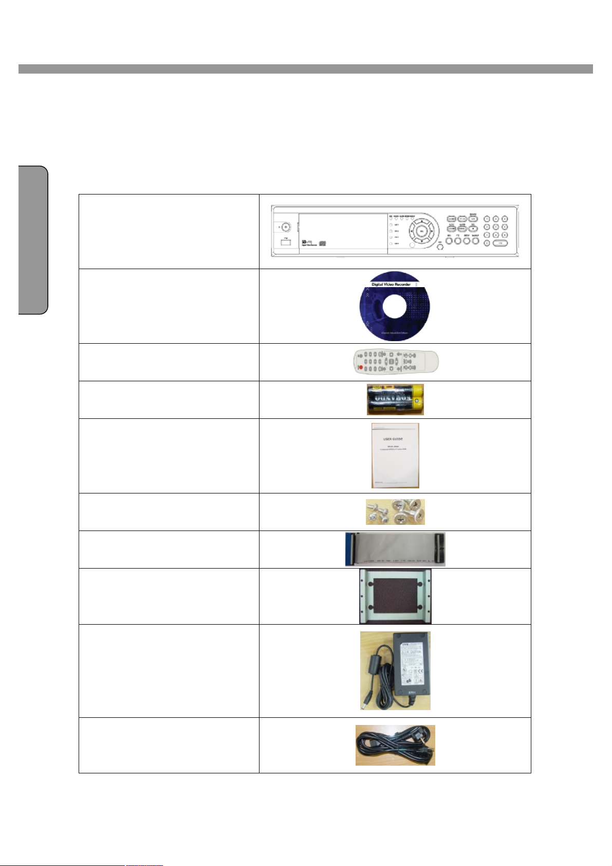
The package contains the DVR set and components as bellows. Please make sure that
the bellow components are included in the package. If there is any missing, please
contact your local vendor.
DVR SET
I
S
H
NETWORK CLIENT S/W CD
REMOTE CONTROLLER
BATTERY
MANUAL
SCREWS FOR HDD
INSTALLATION
IDE HDD CABLE
HDD BRACKET
ADAPTOR
POWER CABLE
4
Page 5
4 Channel DVR User Guide
NGL I SH
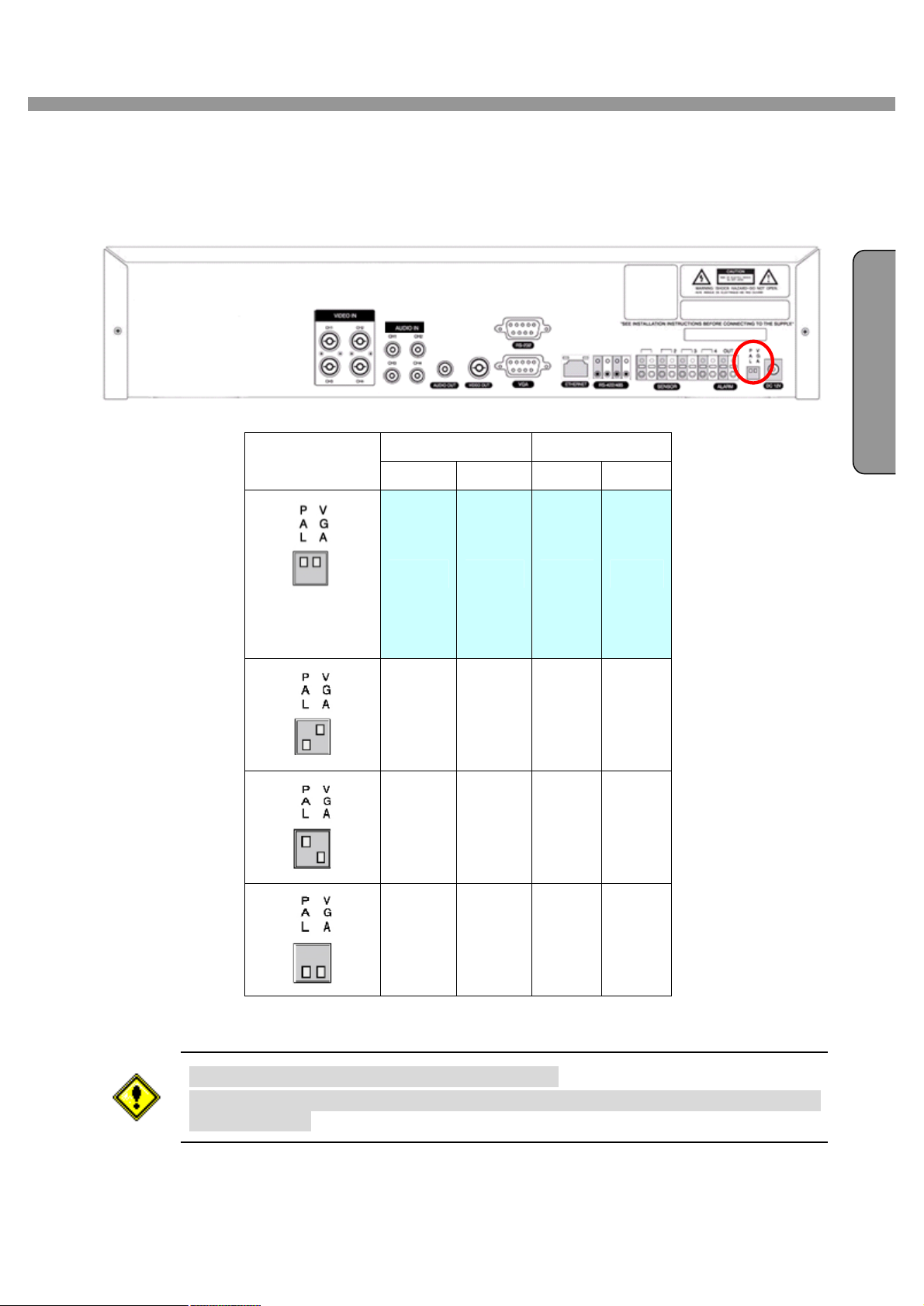
VIDEO SIGNAL SELECT / SETTING
E
SETTING
Factory
Default
Video mode Video output
NTSC PAL BNC VGA
O X O X
X O O X
O X X O
X O X O
Do not change the setting when the power is on.
When the position of the switch is changed, the DVR should be rebooted to apply
the new setting.
5
Page 6
E
N
G
L
I
S
H
4 Channel DVR User Guide
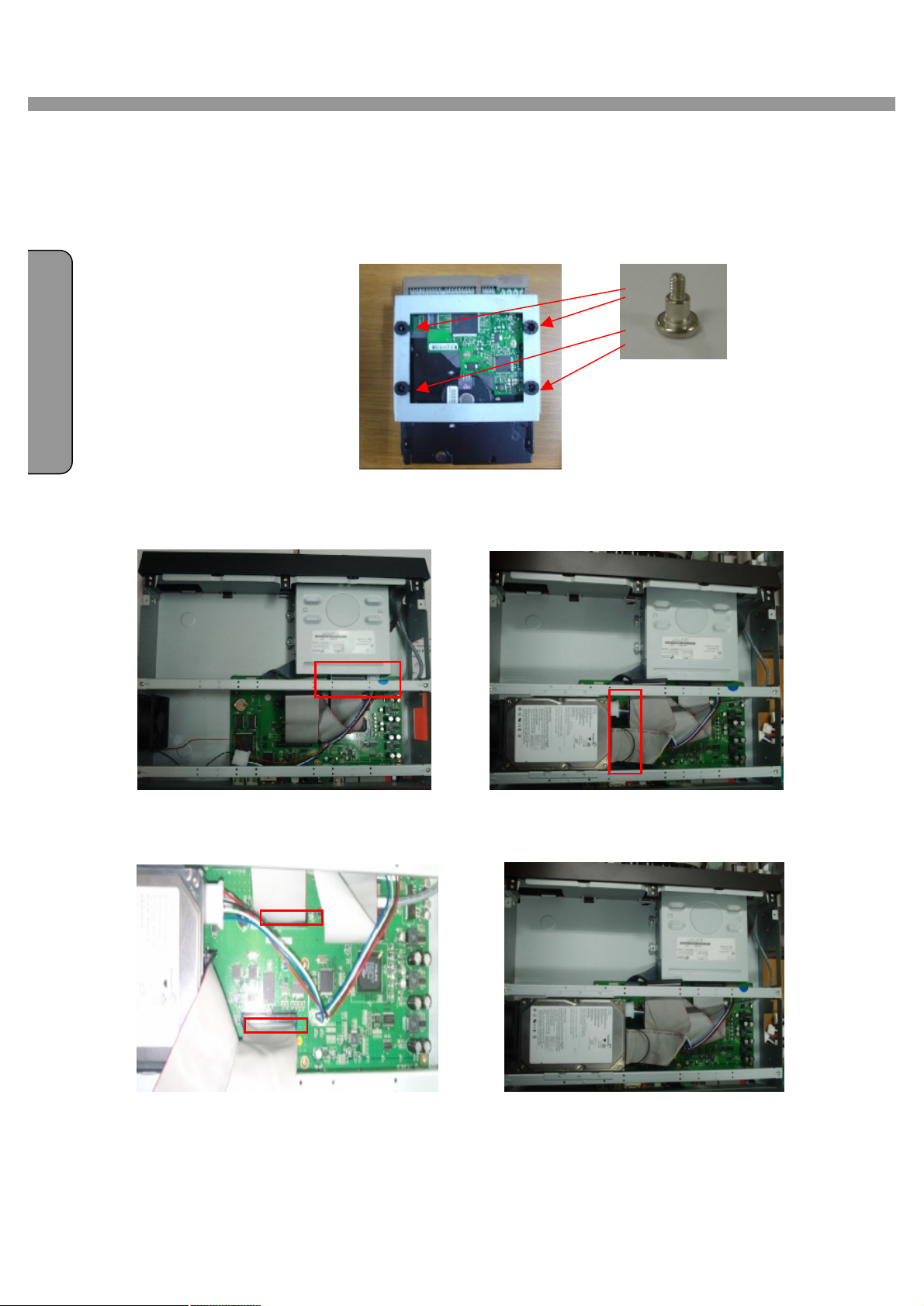
HDD INSTALLATION
Screw the HDD brackets to the HDD.
Firmly insert IDE cable and power cable to the CD-RW Drive and HDD.
Fix the HDD to the chassis.
CD-RW Cable
HDD Cable
6
Page 7
4 Channel DVR User Guide
N
I S
H
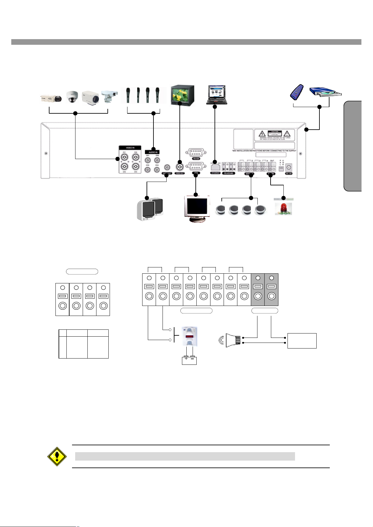
SYSTEM SCHEMETIC
E
G
L
Wiring Camera Control port and Sensor / Alarm Port
RS-422/485
TX+
TX- RX+
1 2 3 4
RS422 R485
1 TX+ DATA+
2 TX- DATA3 RX+
4 RX-
RX-
SENSOR INPUT :Connect two signal lines of sensor (infrared rays sensor, heat perception
sensor, magnetic sensor) to the desired sensor number.(You can set the type-NC or NO- of
sensor at “Setup” mode).
ALARM OUTPUT : Use this at 30V/300mA or less operating voltage and current. When
controlling lamp and AC operated equipment, control it using separate outside relay. During
1 2 3 4 OUT
Sensor
Dried Contact
Adapter
(-)
(+)
ALARMSENSOR
(-)
+12VDC
(+)
normal operation the control output contact is maintained at “Open” status, and during control
output the output contact is changed to “Close(short)” status.
SENSOR inputs need dried contact only. Do not input any electric signal.
7
Page 8

4 Channel DVR User Guide
N
TABLE OF CONTENTS
1. FRONT PANEL...................................................................................................................10
2. REAR PANEL.....................................................................................................................12
E
G
L
I
S
H
3. SETUP..............................................................................................................................13
3-1. Entering SETUP...........................................................................................................................13
3-2. LIVE.............................................................................................................................................15
3-3. RECORD.....................................................................................................................................16
3-3-1. Motion Zones.....................................................................................................................17
3-3-2. Recording Schedule..........................................................................................................18
3-4. SYSTEM......................................................................................................................................19
3-5. NETWORK...................................................................................................................................22
3-5-1. Port...................................................................................................................................22
3-5-2. Network types....................................................................................................................23
3-5-3. DDNS................................................................................................................................25
3-6. Storage........................................................................................................................................25
3-7. Save Setup..................................................................................................................................25
4. LIVE & SEARCH.................................................................................................................26
4-1. Live Screen..................................................................................................................................26
4-2. SEARCH......................................................................................................................................27
4-2-1. EVENT Search..................................................................................................................27
4-2-2. TIME LINE Search.............................................................................................................29
4-2-3. GO TO...............................................................................................................................30
4-2-4. GO FIRST.........................................................................................................................30
4-2-5. GO LAST...........................................................................................................................30
4-2-6. SYSTEM LOG...................................................................................................................30
4-2-7. ARCHIVE LIST..................................................................................................................31
4-3. PTZF operation............................................................................................................................32
4-4. Playback mode.............................................................................................................................33
5. Archiving Video into CD-RW or USB storage device................................................................34
5-1. Capturing images or video............................................................................................................34
5-2. Transferring still images or videos into CD-RW or USB memory stick............................................34
6. Network Client Software......................................................................................................36
6-1. Overview......................................................................................................................................36
6-2. Minimum PC requirements...........................................................................................................36
6-3. Installing the software...................................................................................................................37
8
Page 9

4 Channel DVR User Guide
N
I S
H
6-4. Live viewer...................................................................................................................................37
6-4-1. Main user interface............................................................................................................37
6-4-2. Main control panel.............................................................................................................38
6-5. Search and Playback Viewer........................................................................................................39
6-5-1. Main user interface............................................................................................................39
6-5-2. Main control panel.............................................................................................................40
6-5-3. Back up.............................................................................................................................41
6-6. System configuration....................................................................................................................42
6-6-1. General.............................................................................................................................42
6-6-2. Site....................................................................................................................................43
6-6-3. Event.................................................................................................................................44
6-6-4. Record..............................................................................................................................45
6-6-5. Disk...................................................................................................................................46
6-6-6. About.................................................................................................................................46
7. Firmware Upgrade..............................................................................................................47
A-1. DDNS (Dynamic Domain Name Server).......................................................................................48
A-1-1. Creating an ID and password on our free DDNS Service...................................................48
A-1-2. Domain Name Registration................................................................................................49
A-1-3. Access to DVR by Domain Name......................................................................................51
A-1-4. Domain Name Management..............................................................................................52
A-2. Compatible HDD models..............................................................................................................53
E
G
L
A-3. Specifications...............................................................................................................................54
9
Page 10
E
N
G
L
I
S
H
4 Channel DVR User Guide
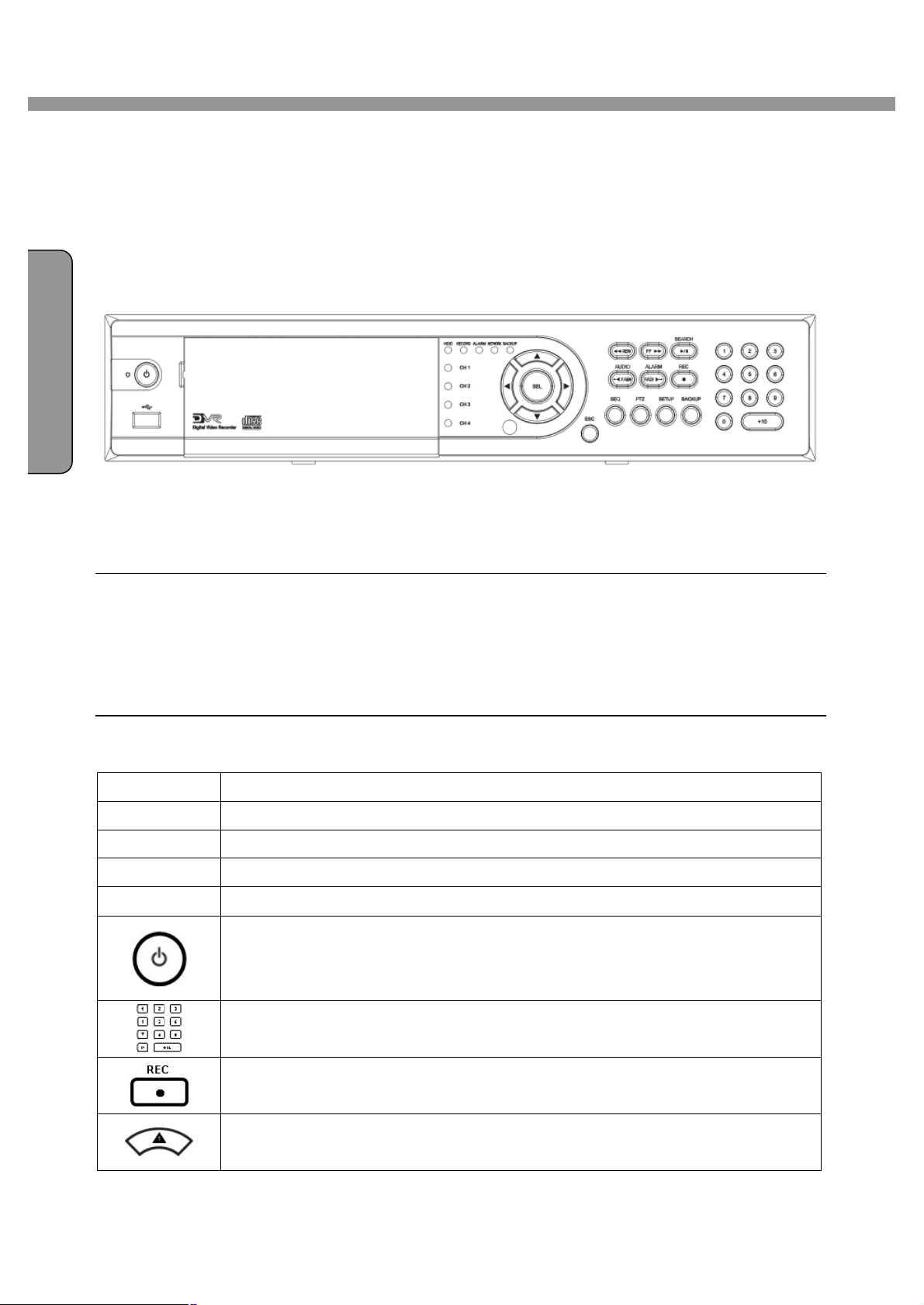
1. FRONT PANEL
The following information will help you operate the front panel controls.
Figure 1.1 Front panel
LED Indication
HDD: LED light is on when the system is accessing video data.
REC: LED light is on when the system is recording video data.
ALARM: LED light is on when alarm sensor(s) is/are triggered or motion is detected.
NETWORK: LED light is on when client(s) is/are connected to the system through the network.
BACKUP: LED light is on when the system save a image to a USB stick or a CD.
Front panel buttons
SEQ Press to start auto sequencing of the screen in full screen mode. (Toggle)
BACKUP Press to start operations involving archiving in live or playback mode.
PTZ Press to control PTZ operation
SETUP Press to launch SETUP menu.
ESC Press to return to previous menu screen.
Power ON/OFF button. Press to start the DVR system or to do shutdown.
When you turn off the DVR system, it will ask for a password. The default
password is 1111.
Press to select a channel number or password. 1, 2, 3 and 4 buttons are
10
usable for 4CH DVR.
Press to start and stop manual recording.
Press to move up the menu items in setup mode and to select camera 1 in
live mode. It is also used as the number 1 when entering password.
Page 11
4 Channel DVR User Guide
NGL I SH
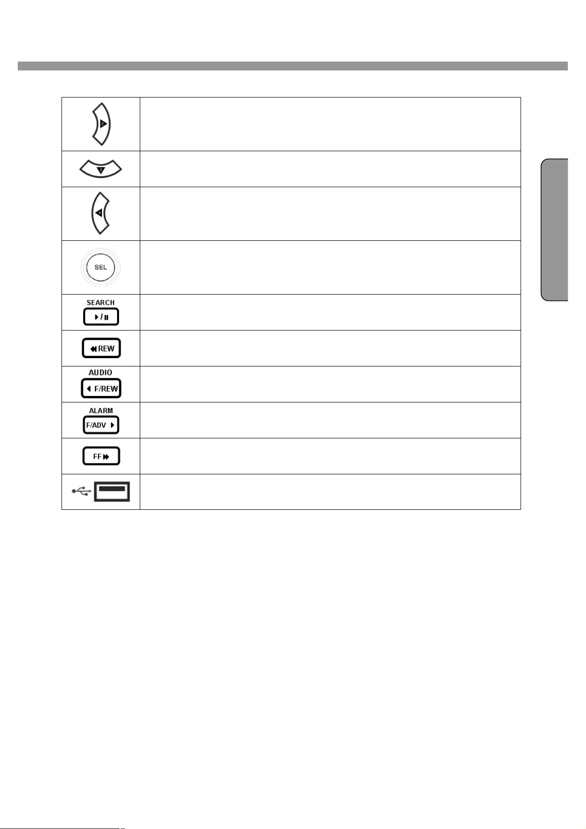
Press to move right in the menu or to change the values in setup mode and
to select camera 2 in live mode. It is also used as the number 2 when
entering password.
Press to move down the menu items in setup mode and to select camera 3 in
live mode. It is also used as the number 3 when entering password.
Press to move left in the menu or to change the values in setup mode and to
select camera 4 in live mode. It is also used as the number 4 when entering
password.
Press to select full screen or quad view in live display mode. It is also used to
select desired menu item or to store the setup value in the menu.
Press to go to the search menu. Event search /Time line search /Log
/Archive search Press to play or to pause the footage in playback mode.
Press to rewind the footage at 1x, 2x, and 4x speed in playback mode.
Jump/Step backward. – In playback mode, the playback position moves 60
seconds backward.
Jump/Step forward – In playback mode, the playback position moves 60
E
seconds forward.
Press to fast forward the footage at 1x, 2x, and 4x speeds in playback mode.
There is a USB port located on the left side of the front panel. This USB port
is used to archive footage into a USB memory stick and USB CD-RW.
11
Page 12
E
N
G
4 Channel DVR User Guide
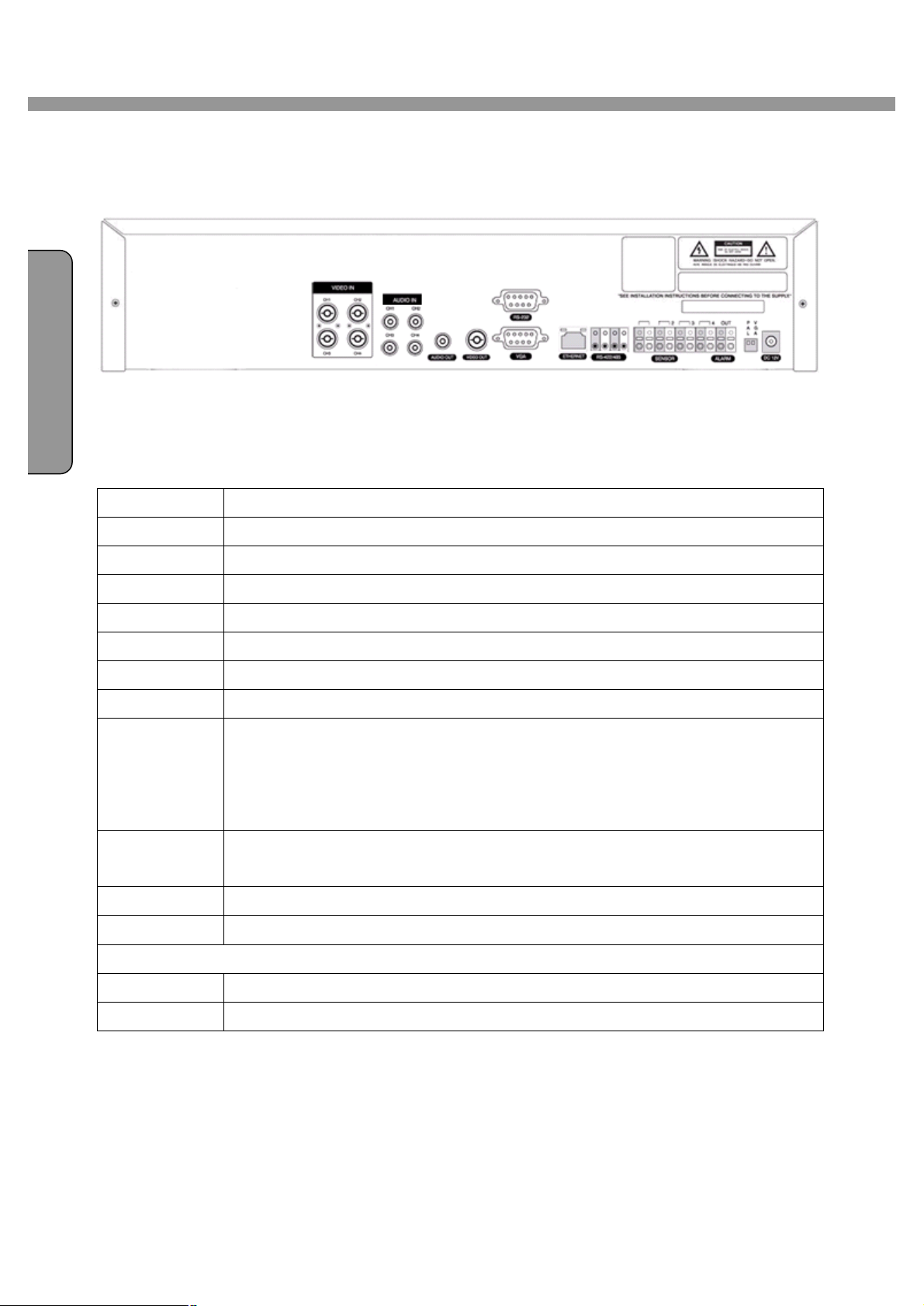
2. REAR PANEL
L
I
S
H
Figure 2.1. Rear Panel
Rear panel connections
TITLE Description
VIDEO IN Four connectors for video input(NTSC/PAL).
VIDEO OUT Composite video output in NTSC/PAL format
AUDIO IN Four connectors for audio input(line level).
AUDIO OUT One connector for audio output(connect a headphone or a speaker).
VGA Connector for VGA monitor
RS-232 For engineering use only
RS-485/422 For camera control use
SENSOR Connector for sensor device connection. 4 sensors can be connected to the
equipment sensor 1, 2, 3, 4 are dedicated to Video channel 1, 2, 3, 4,
respectively. Either normal open (NO) or normal close (NC) sensor can be
selected for each sensor. Simple On/Off switching.
ALARM Connector for alarm device connection. Provides simple On/Off switching
using relay. 0.5A/125V, 300mA/30V
LAN RJ45 connector for LAN connection
DC12V Apply 12V DC using the DC adaptor supplied with the equipment.
SWITCHES : NTSC/PAL, BNC/VGA Select switch
VGA Selection of VGA monitor or Composite monitor
PAL Video type selection of NTSC or PAL
12
Page 13
4 Channel DVR User Guide
N
I S
H
3. SETUP
The following sections detail the initial setup of the DVR
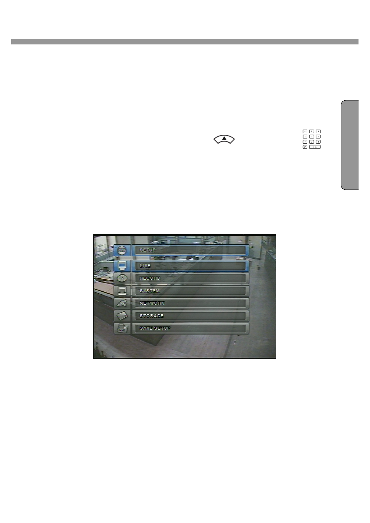
3-1. Entering SETUP
When you press the SETUP button, the DVR will ask for a password. The default password is
1111, which can be entered by pressing the up button ( ) or number 1 button( ) 4
times and then pressing the SEL button. We recommend you protect the system by assigning a
new password immediately. The procedure for assigning a password is found in section 3.4.
After a password has been assigned, enter the password by using the 4 direction keys
(representing 1, 2, 3, & 4), and then press the SEL button for password validation. Once the
password is entered, you will see the screen as shown in Figure 3.1.1. Navigate through the
E
G
L
menu items and press the SEL button to enter the sub-category menu.
Figure 3.1.1. Setup menu screen
13
Page 14

4 Channel DVR User Guide
N
SETUP LIVE OSD
SEQUENCE
SEQ-DWEL TIME
EVENT BEEP
E
G
L
I
S
H
OSD CONTRAST
CHANNEL DISPLAY, SEQ LIST,
BRIGHTNESS, CONTRAST,
HUE, SATURATION
RECORD RESOLUTION
CHANNEL FRAME RATE, QUALITY,
RECORDING, MOTION ZONE,
MOTION SENSITIVITY,
SENSOR TYPE, PRE RECORD,
POST EVENT RECORD, ALARM,
ALARM DURATION, AUDIO
SCHEDULE
SYSTEM DVR ID
DESCRIPTION
LOAD FACTORY DEFAULT
ADMIN PASSWORD
NETWORK PASSWORD
DATE FORMAT
SET DATE & TIME
PTZ CONTROL
LANGUAGE
REMOTE CONTROLLER ID
NETWORK PORT
CLIENT ACCESS
BANDWIDTH SAVING
NETWORK TYPE
DDNS
STORAGE OVERWRITE
FORMAT
SAVE
Table 3.1.1. Setup menu configuration
14
Page 15
4 Channel DVR User Guide
N
I S
H
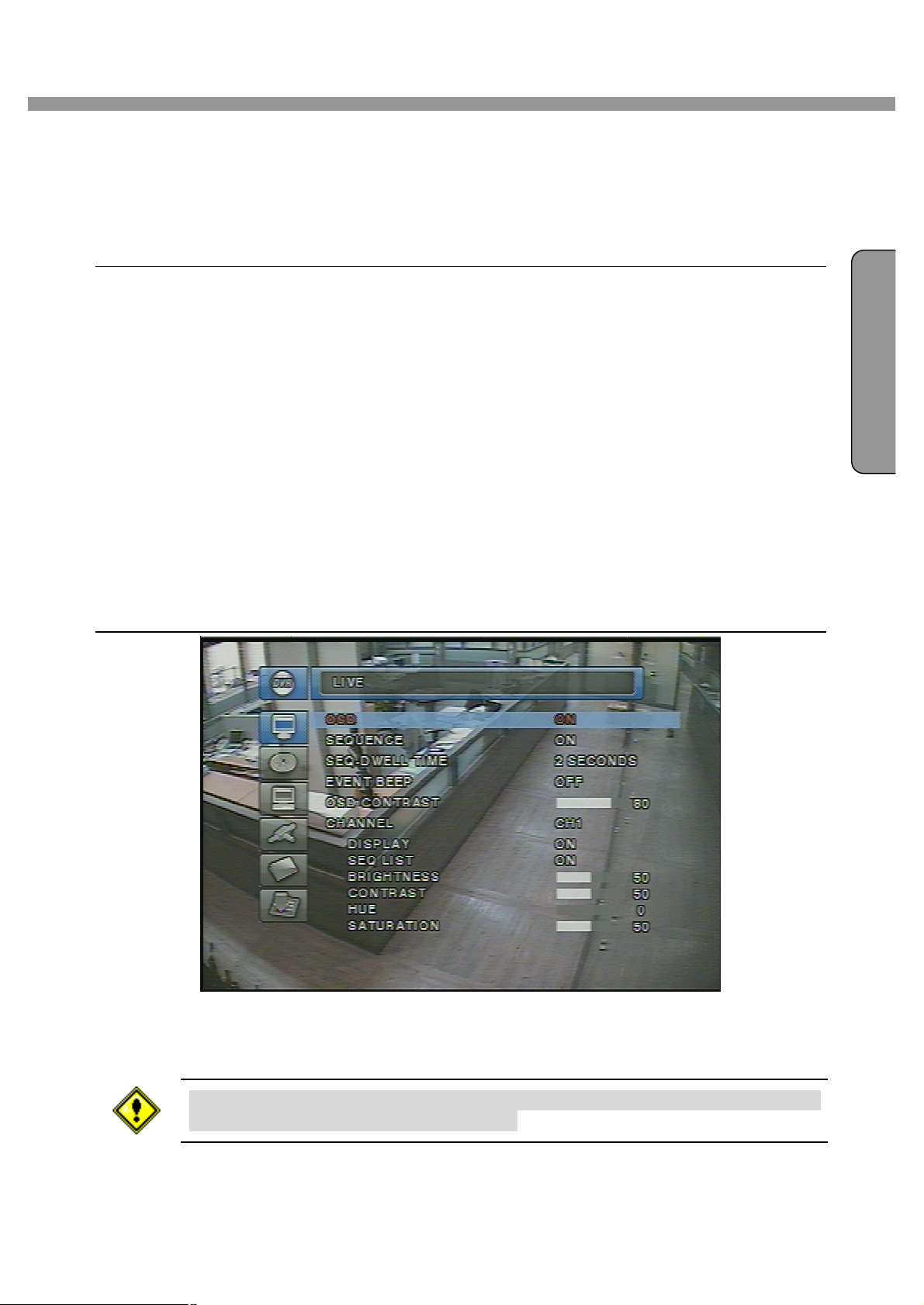
3-2. LIVE
Set values for live display. Navigate through the menu items by pressing the UP/DOWN buttons.
The value of the menu item may be changed by pressing the LEFT/RIGHT buttons.
Menu items in LIVE mode setup
OSD Enable/disable on-screen-display.
SEQUENCE Enable/disable sequential display of video channels in full screen mode
SEQ-DWELL TIME Dwell time for each channel display in sequential display mode
EVENT BEEP Enable/Disable beep alert sound.
OSD CONTRAST Set the visibility level of the On Screen Display (OSD)
CHANNEL Select the channel for applying the following settings by pressing the LEFT/RIGHT
buttons. Change the channel name by pressing the SEL button.
DISPLAY Enable/disable display of the video channel in live display mode
SEQ LIST Enable/disable the specified channel to be included in sequential display mode.
E
G
L
BRIGHTNESS Change the brightness value for the specified channel
CONTRAST Change the contrast value for the specified channel
HUE Change the hue value for the specified channel
SATURATION Change the saturation value for the specified channel
Figure 3.2.1. LIVE mode setup screen
If the values of BRIGHTNESS, CONTRAST, HUE, & SATURATION is changed, the
video will be recorded as same as changed.
15
Page 16

E
N
G
L
I
S
H
4 Channel DVR User Guide
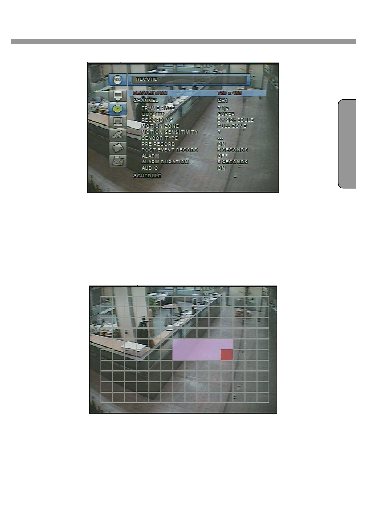
3-3. RECORD
Set the values for recording video. Navigate through menu items by pressing the UP/DOWN
buttons. User can change the value of the menu item by pressing the LEFT/RIGHT buttons.
Menu items in RECORD mode setup
RESOLUTION Set resolution.
CHANNEL Select the channel for applying the following settings. This channel name can be
changed on LIVE menu.
FRAME RATE Set the frame rate for the specified channel. The sum of the frame rate values from
each channel cannot exceed maximum frame rates for a particular recording resolution.
Typical values of the maximum frame rate for NTSC video are 120/100 fps for
360*240(NTSC)/360*288(PAL) and 30/25 fps for 720*480(NTSC)/720*576(PAL).
QUALITY Select the recording quality for the specified channel from normal, high,
and super.
RECORDING Assign the recording mode for each channel. Recording modes: Continuous,
Motion, Sensor, Schedule, and Disable.
MOTION ZONE Select Full Zone or Partial Zone for motion sensing. If the Partial Zone is
selected, screen will be change as shown in figure 3.3.2.
MOTION SENSITIVITY Set the motion sensitivity for the specified channel. Control the
motion sensitivity from 1 to 9.
SENSOR TYPE Set the type of sensor for the specified channel from none,
N/O (normal open), and N/C (normal closed).
PRE RECORD Enable/disable pre-event recording. Pre-event recording time is 5 sec and
only intra-frames are recorded for pre-event recording.
POST EVENT RECORD Set post event recording time duration for the specified channel.
ALARM Enable/disable alarm generation for the specified channel.
ALARM DURATION Set alarm time duration for the specified channel.
AUDIO Enable/disable audio for the specified channel
SCHEDULE Set recording schedule. If this menu item is selected, screen will change as shown
in figure 3.3.3.
16
Page 17
4 Channel DVR User Guide
N
I S
H
E
G
L
Figure 3.3.1. RECORD mode setup screen
3-3-1. Motion Zones
By selecting Partial Zone in the Motion Zone menu, users can set-up the motion sensing zones
in the screen shown in figure 3.3.2. Move around each rectangular zone using 4 direction key
buttons and press SEL button to include the rectangular region as part of the motion sensing
zone. The rectangular blocks included as part of the motion zone are indicated by changing the
color of the blocks.
Figure 3.3.2. Motion Zone selection screen
17
Page 18
E
N
G
L
I
S
H
4 Channel DVR User Guide
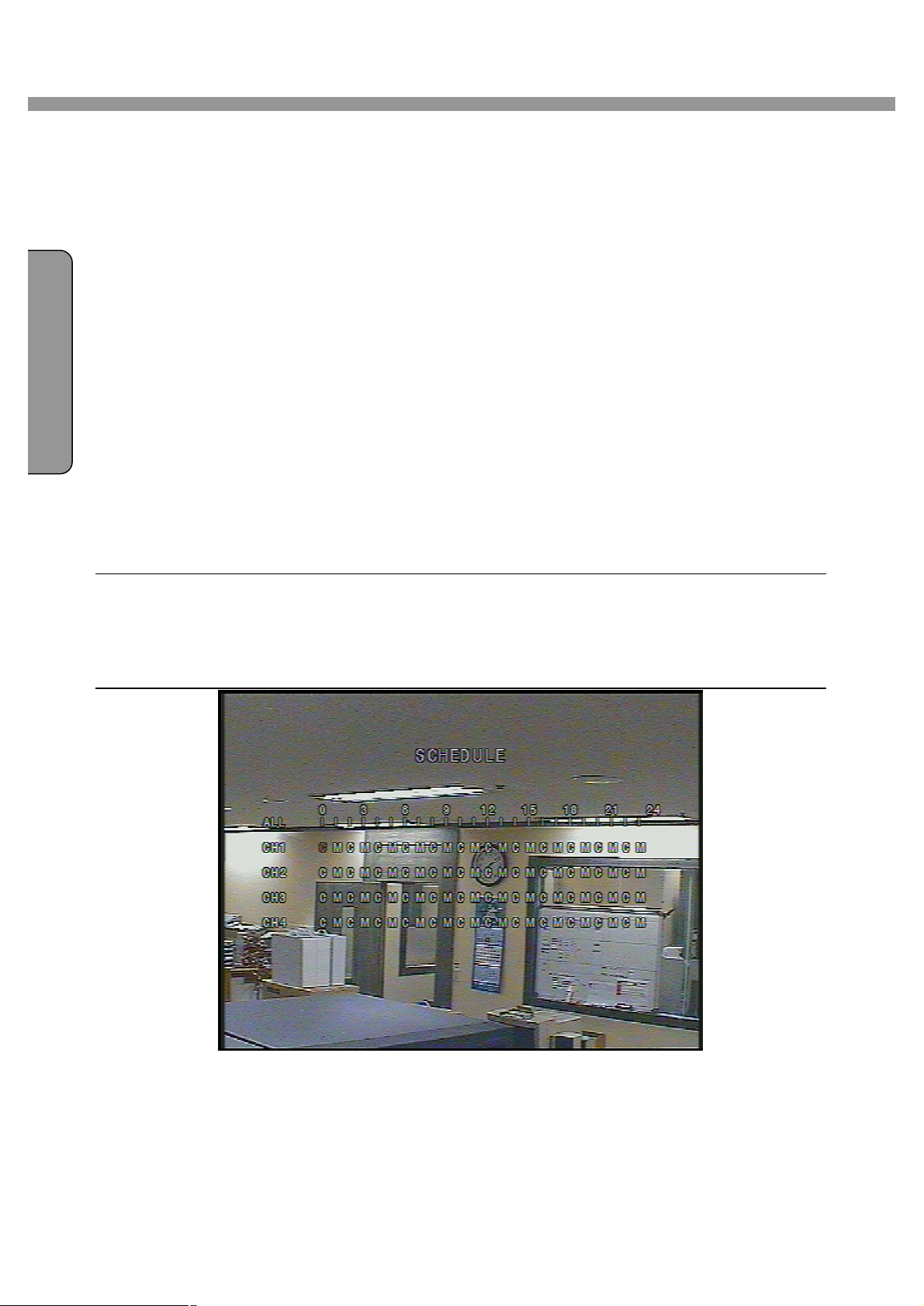
3-3-2. Recording Schedule
Select SCHEDULE in the RECORD menu to set up the recording schedule. Navigate through
the items to highlight using the 4 direction key buttons and set recording schedule using the SEL
button.
[ALL] : When ALL is highlighted, selected recording mode by pressing SEL button is applied to
entire time zone and channels.
[CH_] : When a particular channel is highlighted, selected recording mode by pressing SEL
button is applied to entire time zone for the specified channel.
[ | ] : When one of vertical bars “ | “ is highlighted, selected recording mode by pressing SEL
button is applied to 1, 2, 3, & 4 channels for the selected time zone. (Each vertical bar “ |
“ corresponds with one hour.)
[CH_] and [ | ] Cross : When a particular intersection point is highlighted, selected recording
mode by pressing SEL button is applied to that channel and time zone.
Recording mode in schedule
[ C ] : Continuous recording mode
[ . ] : No recording mode(Display only).
[ M ] : Motion detection triggered recording.
[ S ] : Sensor triggered recording.
Figure 3.3.3. Schedule recording setup screen
18
Page 19

4 Channel DVR User Guide
N
I S
H
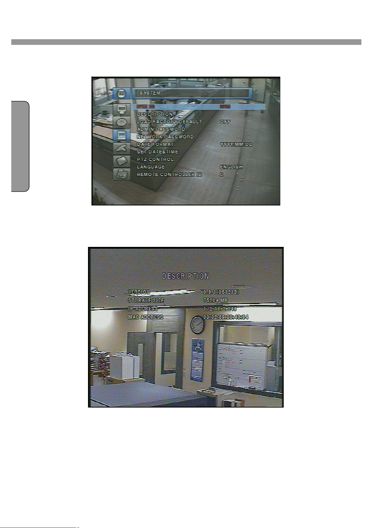
3-4. SYSTEM
In this menu, system parameters can be input. Navigate through the menu items by pressing
the UP/DOWN buttons. User can change the value of the menu items by pressing the
LEFT/RIGHT buttons.
Menu items in SYSTEM
DVR ID The name of the system. Press the SEL button and move through the position for each
alphanumeric character by pressing the LEFT and RIGHT buttons. UP/DOWN buttons
are used to change character for each location.
DESCRIPTION Press SEL button to see the system information.(IP Address, Storage size,
Firmware version)
LOAD FACTORY DEFAULT Choose OFF or ON. If selecting ON, press the SEL button to load
defaults. When Load factory default is selected, DVR will automatically reboot.
ADMIN PASSWORD Set the password for the administrator. Once this menu is selected, the
E
G
L
DVR will ask you current password and new password. Follow the procedure provided by
the DVR. The password numbers (1,2,3,4) can be input by using direction keys
( 1, 2, 3, 4) or number keys( ). The default password is 1111.
NETWORK PASSWORD Set the password of network client. Once this menu is selected, the
DVR will ask you current password and new password. The DVR will guide you through
the entire process of setting up the user password. The password numbers (1,2,3,4) can
be input by using direction keys( 1, 2, 3, 4) or number keys( ).
The default password is 1111.
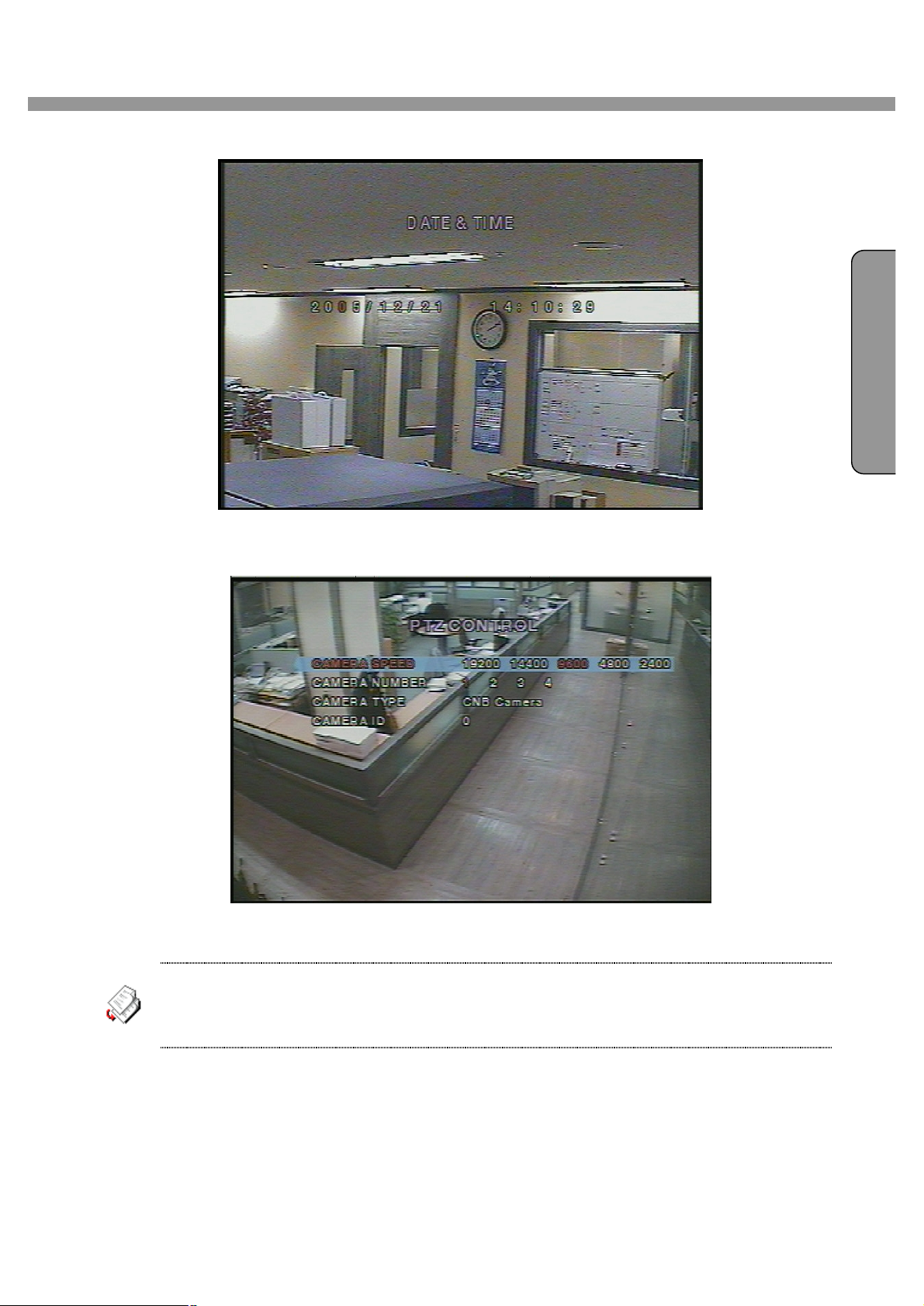
DATE FORMAT Select the preferred date and time display.
SET DATE & TIME Set the present date and time. When data or time is changed, DVR will
automatically reboot.
PTZ CONTROL Set the camera control data speed, number, type and ID.
LANGUAGE Select a language.
REMOTE CONTROLLER ID Select a ID of remote controller. Please take steps as followings.
STEP 1. Select ID from 1 to 9.
STEP 2. Press the same number as ID set in DVR on a remote controller.
STEP 3. Then icon will be displayed on Live screen of DVR that respond to the
remote controller.
19
Page 20
E
N
G
L
I
S
H
4 Channel DVR User Guide
Figure 3.4.1. System setup screen
Figure 3.4.2. DVR information display screen
20
Page 21
4 Channel DVR User Guide
N
I S
H
E
G
L
Figure 3.4.3. Date & Time setup screen.
Figure 3.4.4. PTZ Control setup screen.
To control the PTZ functions of the camera, connect the controller to the RS-485 port.
For speed dome cameras that supports RS-485, connect them directly to the RS-485 port. But if
the camera is controlled with RS-232C, it is needed to use Signal Converter (RS-485 to RS-
232C).
In the PTZ control setting in the setup menu, user can select or set the protocol type of the
camera which is the same as the one that is installed on the site. If the camera has a specific
camera ID, select the camera ID using Left/Right buttons.
21
Page 22
E
N
G
L
I
S
H
4 Channel DVR User Guide
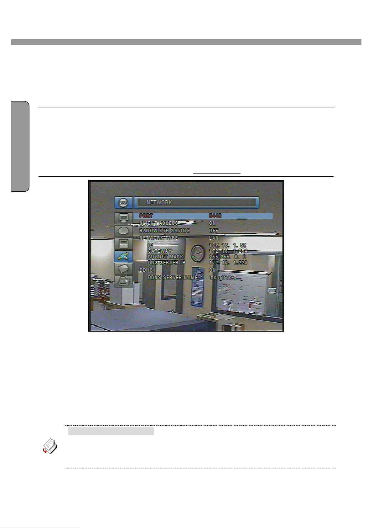
3-5. NETWORK
Network parameters can be input in this screen. These parameters are used for remote clients
who are connected to the DVR over the network.
Menu items in Network Setup screen
PORT Port number of DVR(default : 5445)
CLIENT ACCESS Enable/Disable network client access
BANDWIDTH SAVING Enable/Disable only-key frame transmission. This feature is useful when
network bandwidth is not enough for live video streaming.
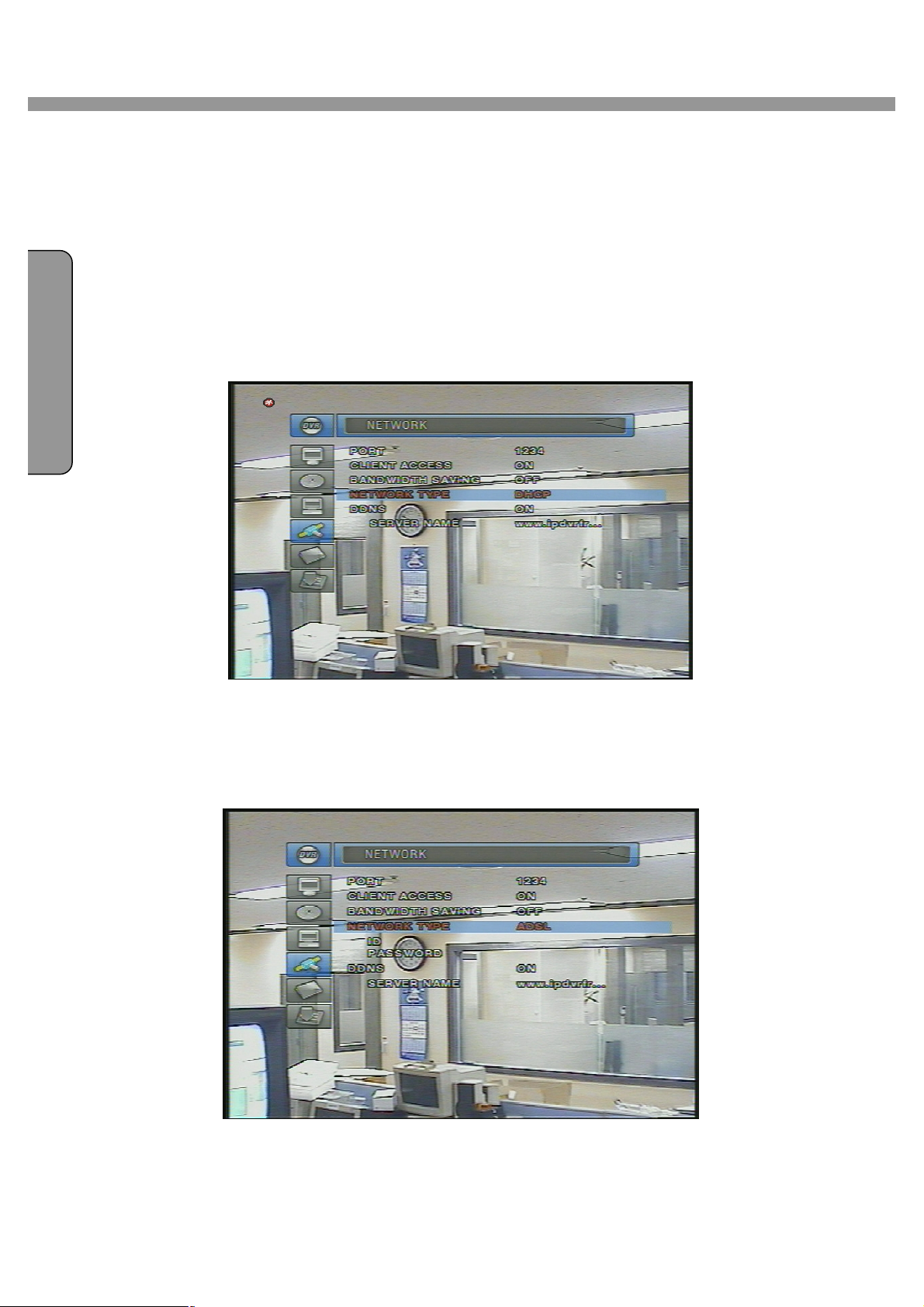
NETWORK TYPE Select a type of network connection from LAN, DHCP, or ADSL.
DDNS SERVER NAME The DDNS sever name is ipdvrfree.com.(Do not change the name)
Figure 3.5.1. Network setup screen
3-5-1. Port
When connecting 1 or more DVRs to a network through an IP sharing device, each device must
have a unique RTSP port number for access to each unit from outside the LAN. Also, the IP
sharing device must be configured for port forwarding, so that each port, when accessed on the
IP sharing device, will forward to the appropriate DVR. This port number is listed next to the Port
menu option in the NETWORK menu. If the user plans to only access the units from within the
same local area network, the RTSP port does not have to be changed.
Network access beyond Router
In order to access beyond Router (Firewall), user must open 1 TCP port. If this port is
not open properly, user can not access DVR beyond a router.
If DVR sets port number with 5445, user has to open 5445 TCP port of your Router.
22
Page 23
4 Channel DVR User Guide
N
I S
H
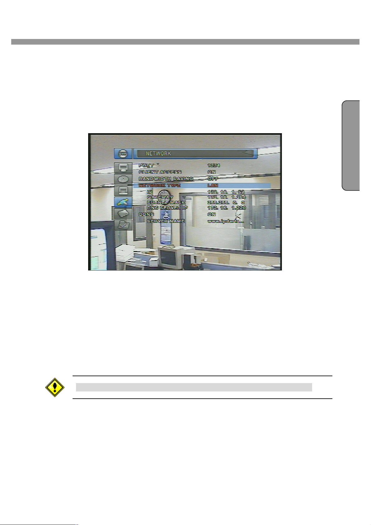
3-5-2. Network types
There are three network types. Each type requires different settings.
LAN
To use the LAN option when connecting the DVR to a network, the following information is
required. If you do not have this information, see your network administrator.
E
G
L
LAN network setting
1. When using private static IP in LAN: Please ask the fixed IP address, Gateway,
Subnet Mask, & DNS server name to your network manager or administrator.
2. When using private static IP that is set in a router:
l IP address: IP address that is assigned in a router.
l Gateway: Gateway of a router
l Subnet Mask: Subnet Mask of a router.
You should open 1 port, if you are using a router. Please refer to “3-5-1. Port”.
Figure 3.5.2. Network setup screen - LAN
23
Page 24
E
N
G
L
I
S
H
4 Channel DVR User Guide
DHCP
Select DHCP to use the DHCP option when connecting the DVR to a network. An IP address is
automatically assigned by the DHCP server, which assigns IP address and other parameters to
new devices automatically. To see the DVR’s IP address, select DESCRIPTION from the
SYSTEM menu. If the network connection does not allow additional IP addresses, then an IP
sharing device will be needed. In this case, forwarding may be needed to allow for a network
connection. For more information on port forwarding, see the documentation for your IP
sharing device or your network administrator.
Figure 3.5.3. Network setup screen - DHCP
ADSL
To use the ADSL option when connecting the DVR to a network, the following information is
required. If you do not have this information, see your network administrator.
Figure 3.5.4. Network setup screen - ADSL
24
Page 25

4 Channel DVR User Guide
N
I S
H
ADSL
ID The user ID for ADSL connection
PASSWORD The password for ADSL connection
User’s ADSL connection must have an RJ45 output to connect to the DVR.
When sharing the connection with other devices, an IP sharing device should be used. In this
case, select LAN as the NETWORK type. User will also need to configure the IP sharing device
for port forwarding to allow for a network connection. For more information on port forwarding,
see the documentation for your IP sharing device, or contact your network administrator.
3-5-3. DDNS
DDNS
Select DDNS ON when you want to connect network with domain name instead of IP address.
E
G
L
DDNS SERVER NAME
ipdvrfree.com is factory default.
Domain name is to be registered on ipdvrfree.com . Please refer to APPENDIX A-1
DDNS (Dynamic Domain Name Server) for the detailed registration procedure.
3-6. Storage
User can set recording mode in the hard disk drive or initiate format of the hard disk drive.
Storage setup
OVERWRITE Overwrite existing material when hard disk drive is full
FORMAT Format hard disk drive
3-7. Save Setup
To preserve the changed setup values, save the values by selecting the SAVE SETUP menu
and select CONFIRM.
25
Page 26
E
N
G
L
I
S
H
4 Channel DVR User Guide
4. LIVE & SEARCH
4-1. Live Screen
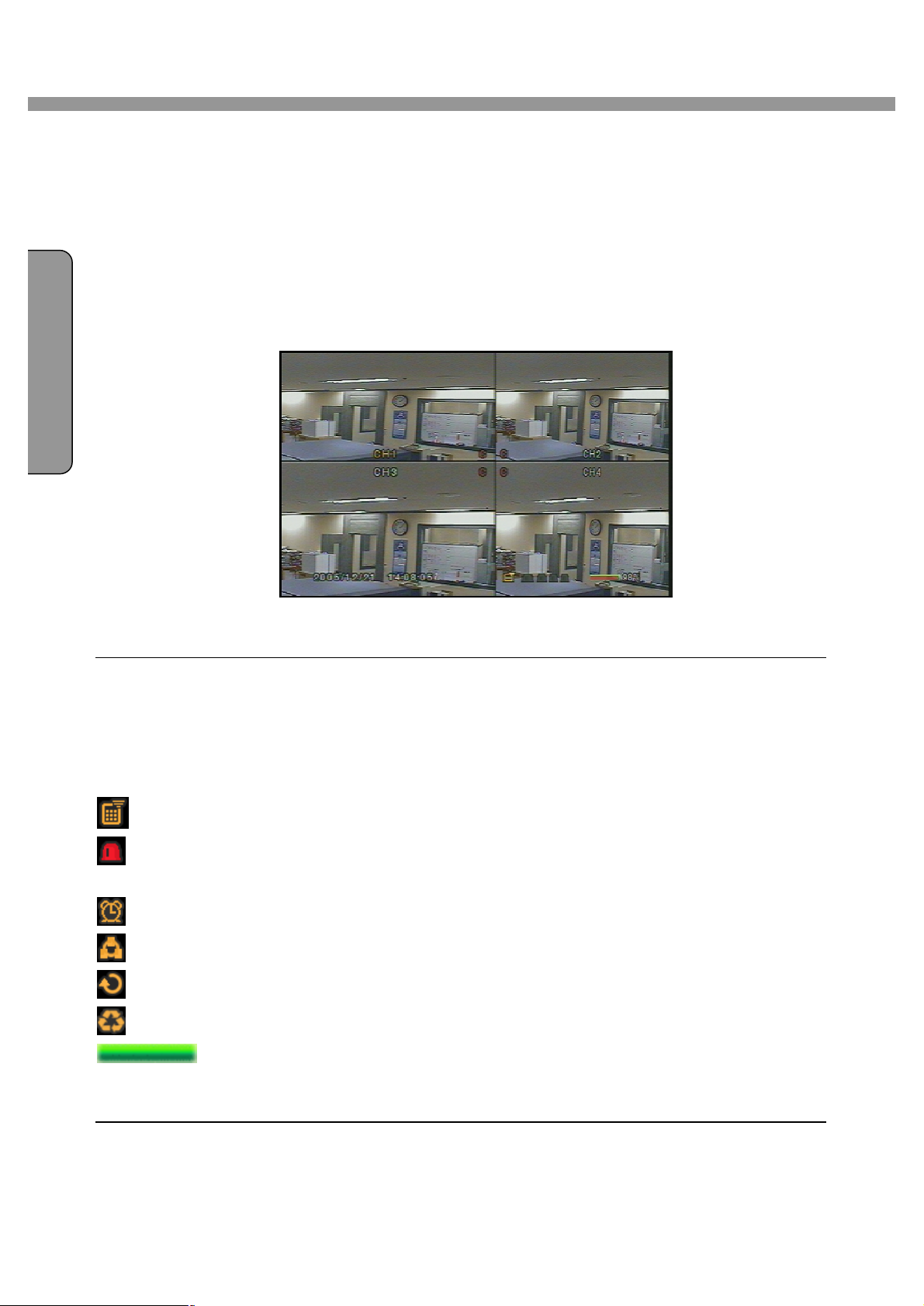
In the Live window, video inputs from the cameras are displayed on the configuration of the
live setup. Figure 4.1.1 shows the layout of the live screen. Various indicators showing the
status of the DVR are shown as OSD symbols. Refer to Table 4.1.1 for the meanings of the
indicators.
Figure 4.1.1. Live Screen
Indicator Icons in Live Screen
C Continuous recording in progress
R Manual recording in progress
S Sensor alarm recording in progress
M Motion alarm recording in progress
Indicates that Remote controller ID function is activated.
Alarm indicator. When there is an alarm (sensor alarm or motion alarm) in the video
channel, this icon will be highlighted in bright red.
Indicates that alarm output is activated.
Indicates that a network client is connected to the DVR.
Indicates that sequencing mode is enabled.
Indicates the HDD is being recycled
Indicates the percentage of recorded data into HDD. 100% will be indicated once
recorded data is full in HDD. This is occurred only in OVERWRITE OFF mode which is
set from storage setup.
26
Page 27

N
I S
H
4-2. SEARCH
Press the SEARCH button in live mode to enter SEARCH.
The screen will appear as in figure 4.2.1.
4 Channel DVR User Guide
E
G
L
Figure 4.2.1. Search window
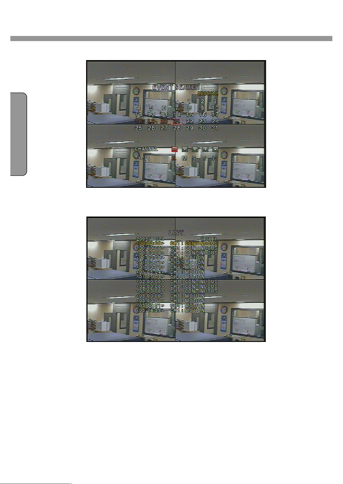
4-2-1. EVENT Search
The EVENT SEARCH window is used to find the stored video. 3 categories of search filters
can be applied: DATE, CHANNEL, and TYPE. Use the SEL button to move down the
categories and use the UP button to move up the categories. The ESC button will return
user to the live screen.
Searching for an event:
1. Select the date of the video to begin searching, Use the LEFT or RIGHT button to
navigate through the day. Use the UP or DOWN button to change the values.
2. Once you have selected the date, press the SEL button to move to the CHANNEL
selector.
3. Use the LEFT or RIGHT button to change the channel selection from ALL to any of the
four available channels.
4. Once you have selected the channel, press the SEL button to move to the TYPE selector.
5. Use the LEFT or RIGHT button to change the type of recording to ALL (A), MOTION (M),
SENSOR (S), MANUAL (R), & CONTINUOUS (C).
6. Once you have selected the type of recording to search for, press the SEL button to
produce a list of instances that fit the search criteria.
27
Page 28
E
N
G
L
I
S
H
4 Channel DVR User Guide
Figure 4.2.2. Event search screen
Figure 4.2.3. Event search list screen
7. Use the UP and DOWN button to scroll through the onscreen listings.
8. Use the LEFT and RIGHT buttons to display events that happened previous to or after
the current selection.
9. Once the desired event has been selected, press the SEL button to playback the
selected video.
10. Press the BACKUP button to archive the video into HDD.
28
Page 29
4 Channel DVR User Guide
N
I S
H
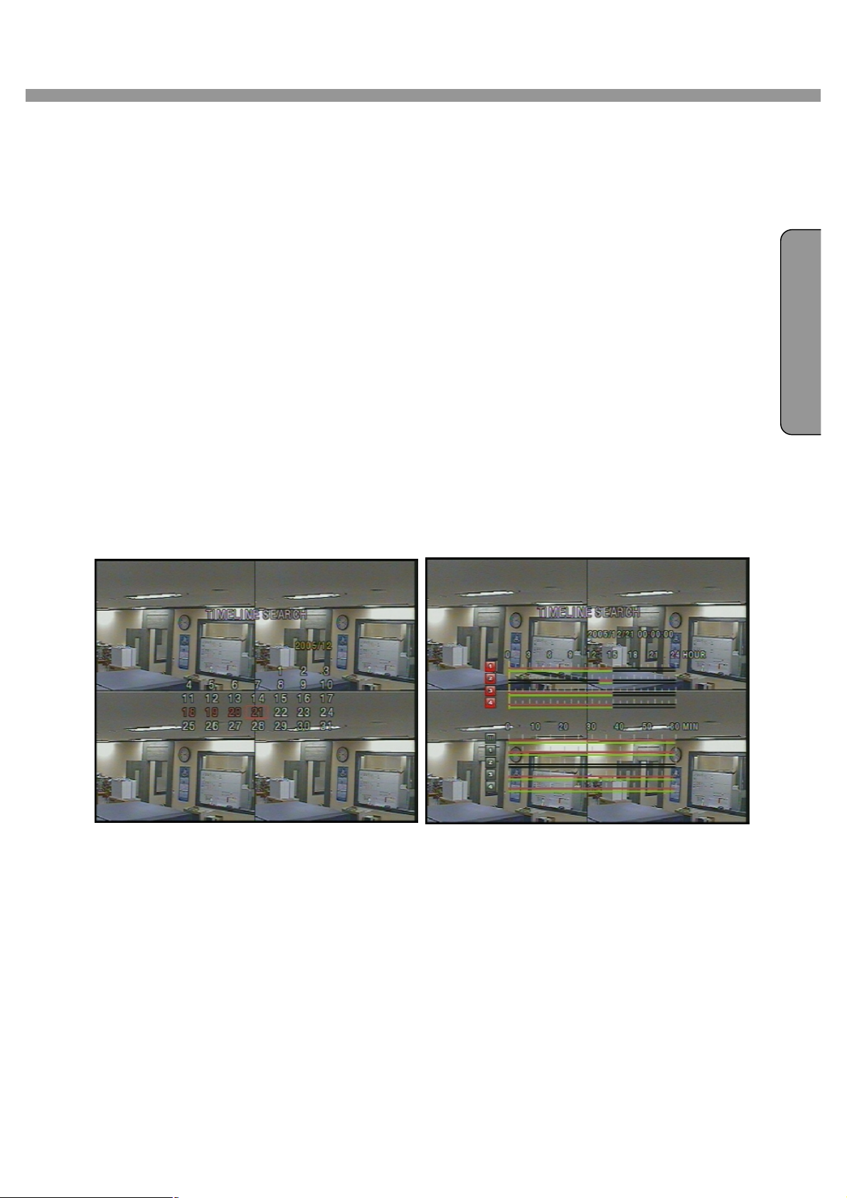
4-2-2. TIME LINE Search
The TIME-LINE SEARCH window is used to find the stored video by using the time line bar.
1. Select the date of the video to begin searching by using the LEFT or RIGHT button to
navigate through the day.
2. Once you have selected the date, press the SEL button to move to the time line search
window.
3. Use the LEFT or RIGHT button to select a time zone on the 24hours time table. Once
you have selected the time zone, press the DOWN button to move to the 60 minutes
time table and select all or each channel for playing back the recorded video.
4. Once you select the time zone, then move the time line select Bar(yellow) to the point
you wish to start playing video (recorded video is indicated by a Red underline) by using
the LEFT or RIGHT button.
E
G
L
5. Press the SEL button to playback the recorded video.
6. Press the BACKUP button to archive the video into HDD.
Figure 4.2.4. Calendar search screen Figure 4.2.5. Time line search screen
29
Page 30
E
N
G
L
I
S
H
4 Channel DVR User Guide
4-2-3. GO TO
You can search for specified data by setting the time and date in this menu. Use the LEFT or
RIGHT button to move from left to right in this menu. Use the UP or DOWN button to set the
date and time.
Figure 4.2.6. GO TO search screen
4-2-4. GO FIRST
You can access to the first data which has been recorded into the HDD disk by pressing this
menu.
4-2-5. GO LAST
You can access to the last data which has been recorded into the HDD disk by pressing this
menu.
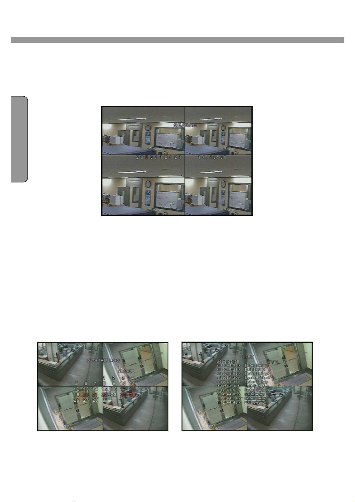
4-2-6. SYSTEM LOG
User can see the system log list by selecting this item.
Figure 4.2.7. SYSTEM Log list screen
30
Page 31

4 Channel DVR User Guide
N
I S
H
4-2-7. ARCHIVE LIST
The ARCHIVE LIST window is used to find booked file list for archiving to the backup device.
1. Select the date on the calendar to begin searching by using the LEFT or RIGHT button.
2. Once you have selected the date, press the SEL button to move to the list of recording
data.
3. Use the UP or DOWN button to scroll through the onscreen listings.
4. Once the desired event has been selected, press the SEL button to see the video in
paused mode.
5. Press the BACKUP button to archive the video into USB memory stick or USB CD-RW.
E
G
L
Figure 4.2.8. Archive list screen
31
Page 32

E
N
G
L
I
S
H
4 Channel DVR User Guide
4-3. PTZF operation
To operate the PTZF functions, connect the controller to the RS-485/422 port on the rear
panel. In the PTZ control setting in the setup menu, user can select or set the protocol type
of the camera which is the same as the one that is installed on the site. If the camera has a
specific camera ID, select the camera ID using Left or Right button.
The PTZ function button is found on the front panel. Once you press the PTZ button, the
screen will appear as in figure 4.3.1. Highlight the item to select and control the cameras by
using the UP and DOWN or LEFT and RIGHT buttons. Please refer to the table 4.3.1. for
description.
Figure 4.3.1. PTZF control screen
Button functions in PTZF control
PAN / TILT Use the UP or DOWN button for TILT and LEFT or RIGHT button for PAN of the
selected camera.
ZOOM / FOCUS Use the UP or DOWN button for ZOOM in or out and LEFT or RIGHT button
for FOCUS near or far of the selected camera.
INITIALIZE Initialize the PTZ settings of the selected camera.
32
Page 33

N
I S
H
4-4. Playback mode
4 Channel DVR User Guide
E
G
L
Figure 4.4.1. Playback mode screen
Button functions in Playback mode
ESC Return to the previous menu screen, search list, or exit menu.
Press to rewind the footage at 1x, 2x, and 4x speeds. Reverse playback
speed is shown as -1x (normal), -2x (2 times normal), and -4x (4 times
normal) at the bottom right of the screen.
Jump/Step backward. – The playback position moves 60 seconds backward.
Press to play or pause recorded video.
Jump/Step forward –Playback position moves 60 seconds forward.
Press to fast forward the footage at 1x, 2x, and 4x speeds. Playback speed is
indicated as +1X, +2X, and +4X for normal, twice, and 4 times of the regular
speed at the bottom right of the screen.
BACKUP Press the BACKUP button to archive the video into HDD.
33
Page 34

E
N
G
L
I
S
H
4 Channel DVR User Guide
5. Archiving Video into CD-RW or USB storage device
To archive a still image or video to a CD-RW or USB storage device, user must make book
marking a still image or video to the hard disk drive.
5-1. Capturing images or video
Still images can be captured and stored into the hard disk drive in live mode or while playing
back recorded video.
Archive in live mode : press BACKUP button to capture and store the still image into the hard
disk drive. Once you press the BACKUP button, the screen will be displayed as shown in
Figure 5.1.1.
Figure 5.1.1. Archive in live screen mode
Archive in playback mode : the DVR will ask whether to store still image or video. If the user
selects still image or video, it will store captured image or video into the hard disk drive. User
can find the list of archived data in SEARCH - ARCHIVE LIST menu.
5-2. Transferring still images or videos into CD-RW or USB memory stick
To begin transferring stored image or video into a CD-RW or USB memory stick,
1. Insert a CD or Connect a USB memory stick. In live mode.
2. Press the SEARCH button and select ARCHIVE LIST from menu to bring up the
ARCHIVE LIST screen which will allow you to specify a date to search stored
images or videos.
3. Press the SEL button to retrieve lists of archived image or video.
34
Page 35

4 Channel DVR User Guide
N
I S
H
E
G
L
Figure 5.2.1. Archive search list screen
4. Select and display one of the files on the screen in the archived list by using the
UP, DOWN and SEL button.
Figure 5.2.2. USB Storage device selection screen
5. Select one of storage devices.
6. Press the BACKUP button to transfer the data to the storage devices. If there is no
enough space in the storage device, the DVR will popup the message that there is
no space in the storage device.
The DVR system is compatible with USB2.0 support. Connect a USB2.0 memory stick
only. When you make a backup file into a CD, use CD-RW device on system. During
the backup, the DVR will operate in Simplex.
If there is proper COCDEC installed in PC, it is possible that the backup data can not
be playbecked. In case of that the backup data in USB device is not properly play
backed in multi-media S/W on PC, user need to install ‘ffdshow’ CODEC that supplied
on Network Client S/W CD.
35
Page 36

E
N
G
L
I
S
H
4 Channel DVR User Guide
6. Network Client Software
The DVR provides a live remote monitoring feature. Remote monitoring requires installation of a
software client program on your PC. A LAN connection using the RJ45 connector on the rear
panel is mandatory for remote connection. For detailed features of the client program, please
refer to the client program user guide.
For local operation purposes, the frame rate is limited to 1 frame/sec when there is no recording
operation in the DVR. When recording is under progress, video frame rate for the live monitoring
will follow the recording frame rate.
6-1. Overview
The remote software supports recording, remote live viewing, search, playback and system
configurations.
By installing the Network Client Software on a Window PC, you can monitor real-time and
recorded images via optional Ethernet network. This includes the ability to monitor video, playback
recorded video and change operating parameters.
DVR allows maximum 4 users to access by network. In high bandwidth network,
maximum 4 user can access on one DVR. In low bandwidth network, one user
network access is highly recommended.
6-2. Minimum PC requirements
Minimum Recommended
CPU Intel Pentium Ⅲ Intel Pentium Ⅳ
500Mhz 2Ghz
Memory 128MB 256MB
VGA Super VGA - 16MB Super VGA - 64MB
Resolution 1024x768 1024x768
Disk space 10MB 10MB
OS Windows 2000 Windows 2000,
Professional, XP
Network 10/100Base T 10/100Base T
Others Direct X 8.1 Direct X 8.1 or Higher
Before installing the client software, check the PC specifications. The Network Client Software
may not perform correctly if the PC does not meet the minimum requirements.
36
Page 37

4 Channel DVR User Guide
N
I S
H
6-3. Installing the software
1. Insert the provided CD into the CD-ROM drive of your PC.
2. Run client.exe to start the installation process.
3. Double click Network Client icon to start the client software.
6-4. Live viewer
When installation is complete, double click the CLIENT icon on your desktop to start the
E
G
L
software.
6-4-1. Main user interface
37
Page 38

PAN/TILT & ZOON FOCUS of the remote
When network is connected, user can playback remote
data.When network is disconnected, user can playback
which
E
N
G
L
I
S
H
4 Channel DVR User Guide
6-4-2. Main control panel
Display the current date and time.
Click this icon to connect to the DVR
IP Address: Enter IP Address or Domain Name of DVR.
Port No.: Enter port number of DVR.
Protocol: Select TCP or UDP.
Click this icon to search for recorded videos.
local data.
Click this icon to lock all operations of client software
Control of
camera.
PAN left /right TILT up/down
ZOOM in/out FOCUS in/out
Click icons to enlarge the channel and to rotate the
channels.
Click this icon to capture a still image
Click this icon to play/pause live video.
Enable or disable recording of live video to local disk
has been set in setup menu.
38
Click this icon to setup configuration of client software.
Click this icon to exit from the operations of client software.
Page 39

alarm output indicator lights up for 5 seconds if
ou
N
I S
H
Use the volume control bar to set the audio level. Y
can select the audio on or off by clicking the audio icon.
HDD storage usage indicator of DVR.
The
alarm output is activated on the DVR.
6-5. Search and Playback Viewer
4 Channel DVR User Guide
E
G
L
6-5-1. Main user interface
You can access to search window by clicking the search icon on the upper left of main user
interface.
39
Page 40

Displays the recording time of the selected data by
adjusting of scale in the middle of the bottom of the main
The calendar shows dates with recorded video in a light
Path: User can select or make a folder that
of the
of the
AVI
E
N
G
L
I
S
H
4 Channel DVR User Guide
6-5-2. Main control panel
user interface.
Click this icon to see live videos.
Blue and the selected date in Red color.
Click this icon to capture a still image of recorded video.
Save
captured image is saved.
File: Enter file name of captured image.
File Format: Select file format from BMP or JPG.
Click this icon to set the beginning time for backup
recorded video in AVI format
Click this icon to set the ending time for backup
recorded video in AVI format
Click this icon to backup the recorded video in
format.
40
Page 41

4 Channel DVR User Guide
d
video.
and 4x
speeds in playback mode.
an
adjust the time line scale and move it to the time you wish to
playback. Then click the play icon to display the recorded
N
I S
H
E
Click to play/pause the recorde
G
L
6-5-3. Back up
You can backup the recorded videos in AVI format on search viewer.
1. First you have to set the beginning time by using the scale. Please click MARK IN icon
, when the scale of the Green timeline is located on the target time as the beginning
time of backup.
The timeline shows recorded data in Green on the bar. You c
video.
Click to shows timeline of recorded data in a hour.
Click to shows timeline of the selected channel.
Click to reverse 1 frame.
Click to rewind the video at 2x
2. Set the ending time on the blue timeline by dragging the scale on the target time as the
ending time of backup and clicking MARK OUT icon . Then, color of the timeline
between the beginning time and ending time will be changed into dark Green.
3. Next, click the backup icon and the pop up window appears as below.
41
Page 42

E
N
G
4 Channel DVR User Guide
L
I
S
H
You can also set the beginning time and ending time on this pop up window.
6-6. System configuration
Click the setup icon to setup the configuration of Network Client Software.
6-6-1. General
Once you click the setup icon, this pop up window appears. Select security options and set a
password.
Then when you access any of the selected functions, you need to enter the password.
You can also set the save path for capturing, backup.
42
Page 43

4 Channel DVR User Guide
.
Confirm
Old
N
I S
H
l Security Option: Set a password for security options.
Initial PW setting: Do not enter any PW on ‘Old Password’
Enter the same PW on ‘New Password’ and ‘
Password’, then press ‘OK’ button.
From 2nd PW setting: User need to enter PW on ‘
Password’ tochange PW.
E
G
l Save Path: Specify the location to record the receiving video for Backup
and still image for Capture.
l Automatic reconnection: If a user selects this function, client S/W will
automatically try to connect the finally connected IP address, after the
network is disconnected.
l Display network statistics: If a user selects this function, client S/W
will display network status, Bit rate and Frame rate.
l Time Format: Change the way the Client software displays the time.
6-6-2. Site
This option shows the channel information of the DVR and allows you to change the channel
title.
L
You may use alpha and numerical characters for channel name. (i.e. [A~Z], [a~z]
or [0~9])
43
Page 44

E
N
G
L
I
S
H
4 Channel DVR User Guide
6-6-3. Event
You can set event items, the amount of local disk space you want to allow, and the save path for
the log.
l LOG – Select to save event log into ‘log file’.
l ICON – Select to display event on live video.
l EVENT LIST – Select to show event on ‘Event List” window of live mode.
You can search and check the recorded log data.
44
Page 45

4 Channel DVR User Guide
N
I S
H
6-6-4. Record
You can set the recording conditions for Always, Event, or Auto recording. You can also select
individual channels or all channels to record.
E
G
L
When you set the recording condition to event, you can set event for motion or alarm with
duration. And you also can set each or all channels to record.
45
Page 46

E
N
G
L
I
S
H
4 Channel DVR User Guide
6-6-5. Disk
You can select the local disk to use and the amount of disk space you want to allow the program
to use for recording. You can also select the option to overwrite data or stop recording when the
maximum amount of disk space is full.
C:\storage will be created and the data will be recorded in this folder.
6-6-6. About
“About” provides network client version information.
46
Page 47

4 Channel DVR User Guide
N
I S
H
7. Firmware Upgrade
The DVR is designed to be upgraded through firmware updates. Firmware upgrades can be
initiated in engineering mode. To start engineering mode, do the following:
In order to upgrade, the upgrade firmware file must be copied into the USB memory stick.
Create a new folder name as ‘UPGRADE’ into the USB memory drive and copy the new
firmware file “app.bin” into the folder.
The folder name should be “upgrade”.
The upgrade firmware must be downloaded from the USB memory stick only.
Do the firmware upgrade as follows:
1. Press the SETUP button and enter the admin password.
2. Go to the SYSTEM and select the ADMIN PASSWORD.
E
G
L
3. Enter the password as “12341234”, and press the SEL button.
4. The engineering mode screen “DVR DIAGNOSTICS” will appear.
5. Select USB UPGRADE, and then the upgrading will start automatically.
6. After the upgrade is completed, DVR will reboot and “DVR DIAGNOSTICS” will appear
again. Select BOOT APPLICATION to reboot DVR.
Figure 6.1. Engineering mode screen
It is highly recommended that user should not enter “MAC Configuration”, “RTC
Configuration”, and “License Key”. These fields are only for production purpose. If
user enters these fields and change setting or value, it will cause system failure
and malfunction.
47
Page 48

E
N
G
L
I
S
H
4 Channel DVR User Guide
APPENDIX
A-1. DDNS (Dynamic Domain Name Server)
If you are using DYNAMIC addressing from your ISP (Internet Service Provider), you will need
to register with our DDNS service. We recommend that you first determine if you are using
dynamic addressing and, if so, register your DVR on our DDNS website.
You do not need to register with our DDNS service if you were supplied a STATIC IP address
from your ISP. Please check with your ISP if you are unsure of how your IP address is
configured. To join our DDNS service, you will have to provide an ID and Password.
A-1-1. Creating an ID and password on our free DDNS Service
1. Access our DDNS Website by going to: http://www.IpdvrFree.com
2. Click on the “Member Join” button, on the lower right hand side of the webpage.
48
Page 49

4 Channel DVR User Guide
N
I S
H
3. Enter an ID (which must be more than 4 and less than 12 characters, alpha and or numerical).
E
G
L
Please check your ID with the “[check]” button to make sure the ID you choose is available.
Choose your Password (which also must be more than 4 and less than 12 characters, alpha
and or numerical). Confirm your (Password). Enter your Name and E-Mail address.
4. The registration will be complete once you click the “OK” button.
The DDNS Service Administer will send a confirmation e-mail to the
Subscriber’s e-mail address, so please enter your e-mail address correctly.
A-1-2. Domain Name Registration
49
Page 50

E
N
G
L
I
S
H
4 Channel DVR User Guide
1. Once your registration is complete, enter your User ID and Password on the main page.
Once you are logged on, you should see the following message:
“Welcome to DVR management server : guest”
2. After login, click the “Registration” button to go to the Server Registration page.
3. At the Server Registration page, enter the “Serial Number” and “Registration No.” which is
attached to the rear of the unit.
4. Choose a “Domain name”. Remember: the ID and password you used to register with
our DDNS service is separate and not the same as your “Domain name”.
You may use alpha and numerical characters as well as hyphens for your Domain name. (i.e.
[A~Z], [a~z], [0~9] or [-] for your domain name and it is case sensitive). Please check your
Domain name with the “[check]” button to make sure the Domain name you choose is available.
Registration will be complete once you click the “OK” button.
50
Page 51

4 Channel DVR User Guide
N
I S
H
5. After your Domain name registration is complete, click the “List” button at the top of the page,
your Domain name should be appear on the list if your registration was successful.
E
G
L
A-1-3. Access to DVR by Domain Name
If your DDNS service registration is successful, you can access your DVR through the provided
Network Client S/W.
Access via the Network Client S/W
Open your Client S/W program and click the on the “connect” button. A DVR Server
Management window will appear.
Enter your domain name in the “IP Address” field at the Server Connect window.
(Refer to your Network Client S/W manual for more detailed instructions.)
51
Page 52

E
N
G
L
I
S
H
4 Channel DVR User Guide
A-1-4. Domain Name Management
You can register multiple domain names at the DDNS Service website. You can also edit or
delete your domain name here at anytime.
When you click your URL from the Host Name LIST, you can access a specific DVR by your
web browser. The “Status” column shows the elapsed time since your last update.
Status Specification
Elapsed time since last update is Less than 5 minutes
Elapsed time since last update is more than 5 minutes and less then 20 minutes
Elapsed time since last update is more than 20 minutes
No update history
Modifying or Deleting your Domain name:
Check ① and click “[Info change]” to modify your Domain name information.
Check ① and click “[Delete]” to delete your Domain name.
52
Page 53

N
I S
H
A-2. Compatible HDD models
4 Channel DVR User Guide
BRAND CAPACITY
HITACHI
MAXTER
WESTERN
DIGITAL
SEAGATE
80GB 7200RPM 2M E-IDE
160GB 7200RPM 8M E-IDE
250GB 7200RPM 8M E-IDE
80GB 7200RPM 2M E-IDE
160GB 7200RPM 8M E-IDE
250GB 7200RPM 8M E-IDE
80GB 7200RPM 2M E-IDE SAMSUNG
160GB 7200RPM 2M E-IDE
80GB 7200RPM 2M E-IDE
160GB 7200RPM 8M E-IDE
250GB 7200RPM 8M E-IDE
40GB 7200RPM 2M E-IDE
80GB 7200RPM 2M E-IDE
160GB 7200RPM 2M E-IDE
250GB 7200RPM 2M E-IDE
RPM BUFFER INTERFACE
E
G
L
53
Page 54

4 Channel DVR User Guide
N
A-3. Specifications
E
G
L
I
S
H
VIDEO
AUDIO INPUT & OUTPUT 4 Line In (RCA)
ALARM INPUT & OUTPUT 4
OS RTOS
RECORD
RECORDING SPEED MAX. 120fps/4CH(352x240/CH)
MULTI TASK TRIPLEX Record, playback and transfer
INPUT 4 composite BNC (NTSC/PAL) – 1.0Vp-p
OUTPUT(Selectable)
COMPRESSION MPEG-4
VIDEO FORMAT NTSC PAL
RESOLUTION 360x240, 720x480 360x288, 720x576
MAX. 30fps/4CH(704X480/CH)
MODE Manual, Motion, Sensor, and Schedule
METHOD By Resolution, Frame rate, & Quality
1 composite BNC (NTSC/PAL) – 1.0Vp-p
1 VGA
1 Line Out (RCA)
1
MAX. 100fps/4CH(352x288/CH)
MAX. 25fps/4CH(704X576/CH)
CONTROL UNIT IR Type Remote Control and Front keys
CONSOLE 1 RS-232C SERIAL PORT
CAMERA CONTROL 1 RS-485
NETWORK
HDD CAPACITY 1EA Max. 500GB
ELECTRONICAL ADAPTOR Input: AC100-240V, 50/60Hz, 1.5A
SPECIFICATION CONSUMPTION About 25W
ENVIRONMENTAL Operation Temperature
SPECIFICATION HUMIDITY 30% ~ 90%
SIZE DIMENSION 432(W) X 350(D) X 88(H)mm
WEIGHT 3.2 Kg (HDD included weight)
INTERFACE ADSL, LAN
DYNAMIC IP DDNS
LAN PORT 1 10/100-base T Ethernet
FUNCTIONS Live, Search, P/T/Z/F, Backup
NETWORK Still Image & Video data BACKUP
CD-RW / USB STICK Still Image & Video data
5°C ~ 40°C
54
Page 55

4 Channel DVR User Guide
사용자 매뉴얼
4Channels Digital Video Recorder
V1.1
55
Page 56

K
O
N
4 Channel DVR User Guide
안전 주의 사항
R
E
A
. 설치 전
– 설치하기 전에 반드시 전원을 끈 상태에서 설치하시기 바랍니다.
– 감전 및 화재의 위험이 있으므로 습기가 많은 곳에 설치하지 마십시오.
– 감전의 위험을 막기 위해 반드시 접지선을 연결해야 합니다.
. 사용시
– 제품의 덮개를 열 경우, 전기적 충격의 위험이 있으므로, 전문 설치자 이외는 제품의
덮개를 열지 마십시오.
– 규격 온도와 습도 범위 이내의 조건에서 사용하십시오.
– 화재의 원인이 되므로 하나의 콘센트에 여러 개의 전원 플러그를 동시에 꽂아 사용하지
마십시오.
– 고장의 원인이 되므로 제품 위에 물이 담긴 그릇이나 무거운 물건을 올려 놓지 마십시오.
– 폭발 및 화재의 위험이 있으므로 프로판 가스, 가솔린 등 인화성 가스나 분진이 발생하는
장소에서는 사용하지 마십시오.
– 감전의 위험이 있으므로 젖은 손으로 전원 플러그를 만지지 마십시오.
– 냉각 환풍구 안으로 전기가 통하는 물질이 들어가지 않도록 주의해 주십시오.
– 코드가 파손되면 감전 및 화재의 위험이 있으므로 전원 코드 부분을 무리하게 당기지
마십시오.
– 내장되는 리튬 건전지를 임의의 다른 제품으로 교체할 경우 폭발의 위험이 있으므로
56
Page 57

4 Channel DVR User Guide
ORE A
N
반드시 동일 제품이나 동종의 제품으로 교체해야 합니다. 또한 폐 건전지는 환경 오염의
원인이 될 수 있으므로 처리 시 주의해 주십시오.
– 건전지를 불 속에 넣거나 가열하면 안되며, 또한 단락 시키거나 분해하면 위험합니다.
- 리모컨(Remote Controller)에 사용하는 건전지는 충전하여 사용하지 마십시오
. 분해 및 청소
– 고장, 감전 및 상해의 위험이 있으므로 제품을 임의로 분해, 수리 및 개조를 하지
마십시오.
– 고장 및 감전의 원인이 되므로 외관 청소 시 물이나 신나 또는 유기용제를 사용하지
마십시오. 외관을 청소할 때는 마른 헝겊으로 닦으시기 바랍니다.
K
. 설치 시
– 원활한 방열을 위해서 냉각 환풍구와 벽면 사이는 15cm 이상의 공간을 확보하여
설치하십시오.
– 제품이 낙하하면 부상당하거나 고장의 원인이 되므로 반드시 평평한 곳에 설치하십시오.
– 제품의 변형 및 고장의 원인이 되므로 직사광선이나 열을 많이 받는 곳을 피하십시오.
– DVR 저장 중에 카메라를 설치할 경우, 타 채널 영상이 깨어질 수 있습니다. 카메라 설치
후에 저장을 시작하는 것이 좋습니다.
. 사용시
– 제품이 작동 중이거나 이동시킬 때는 충격이나 흔들림이 없도록 주의하시기 바랍니다.
– 제품이 작동 중일 때는 제품을 이동시키지 마십시오.
– 제품에 강한 충격을 주거나 던지지 마십시오.
57
Page 58

K
O
N
4 Channel DVR User Guide
구성품
당 제품은 DVR 세트 및 그 외 구성품을 아래와 같이 포함하고 있습니다. 제품에 아래의 구
성품이 정확히 포함되어 있는지 확인하시기 바랍니다. 만약 어떤 구성품이 없는경우에는 제
품 공급자에게 문의하시기 바랍니다.
DVR SET
네트워크 접속 프로그램 CD
리모컨
R
E
A
BATTERY
사용자 매뉴얼
HDD 고정나사
HDD 연결 케이블
HDD 고정 브라켓
아답터
파워 케이블
58
Page 59

4 Channel DVR User Guide
ORE A
N
VIDEO 출력 선택
SETTING
Factory
Default
Video mode Video output
NTSC PAL BNC VGA
K
O X O X
X O O X
O X X O
X O X O
제품의 출력 선택을 변경 후에는 전원을 껐다 다시 켜야 적용이 됩니다. 전원
이 인가 된 상태에서 변경할 경우에는 적용이 되지 않습니다.
59
Page 60

4 Channel DVR User Guide
O
N
하드디스크(HDD)와 HDD 브라켓을 나사로 체결
하드디스크(HDD) 설치
K
R
E
A
IDE HDD cable과 Power Cable을 CD-RW과 하드디스크에 연결
HDD가 장착된 HDD 브라켓을
케이블 연결도 DVR 본체에 장착
CD-RW Cable
HDD Cable
60
Page 61

4 Channel DVR User Guide
KORE AN
시스템 구성
RS485/422 단자 및 SENSOR /ALARM 연결 방법
RS-422/485
TX+
TX- RX+ RX-
1 2 3 4
RS422 R485
1 TX+ DATA+
2 TX- DATA3 RX+
4 RX-
센서: 각종 센서(적외선 센서, 열선 감지기, 마그네틱 등)의 신호선 (2선)을 각 센서단자
(1~4)의 좌측과 우측에 각각 연결합니다. (센서의 N/O과 N/C 형식설정은 설정항목에서
지정합니다.)
알람: 알람출력단자 (OUT)에 각종 알람장비 (경광등, 사이렌, 외부릴레이 등)의 신호선 (2
선)을 좌측과 우측에 각각 연결합니다. 알람출력 단자는 동작전압 30V, 300mA 이하
1 2 3 4 OUT
Sensor
Dried Contact
Adapter
(-)
(+)
ALARMSENSOR
(-)
+12VDC
(+)
에서 사용하십시오. 전등 및 AC로 동작되는 기기를 제어할 경우에는 별도의 외부릴
레이를 이용하여 제어 하십시오.
센서입력 단자에 전원을 인가하지 마십시오. 만약 센서입력에 전원이 연결되면
시스템 오작동의 원인이 될 수 있습니다.
61
Page 62

4 Channel DVR User Guide
O
N
목 차
안전 주의 사항 ......................................................................................................................56
1. 전면부 램프 및 버튼 설명 ...................................................................................................64
2. 후면부 설명.......................................................................................................................66
3. 시스템 설정.......................................................................................................................67
3-1. 설정.......................................................................................................................67
3-2. 라이브 화면 설정 .....................................................................................................69
3-3. 녹화기능 설정..........................................................................................................70
3-3-1. 동작감지 영역 설정 ........................................................................................71
3-3-2. 일정 녹화 .....................................................................................................71
3-4. 시스템....................................................................................................................73
K
R
E
A
3-5. 네트워크 .................................................................................................................76
3-5-1. 포트.............................................................................................................76
3-5-2. 네트워크 종류 ...............................................................................................77
3-6. 저장 장치 ...............................................................................................................80
3-7. 설정 저장 ...............................................................................................................80
4. 주요 기능..........................................................................................................................81
4-1. 메인 화면 ...............................................................................................................81
4-2. 검색 및 재생...........................................................................................................83
4-2-1. 검색의 시작 ..................................................................................................83
4-2-2. 검색 메뉴 설명..............................................................................................83
4-3. PTZ 작동 ................................................................................................................87
5. CD-RW / USB Memory Stick 을 이용한 데이터 백업 ...............................................................88
5-1. 정지영상 백업..........................................................................................................88
5-1-1. 저장 정보 생성 방법.......................................................................................88
5-1-2. CD-RW / USB 저장장치로 백업방법 .................................................................88
5-2. 동영상 백업 ............................................................................................................89
5-2-1. 저장 정보 생성 방법.......................................................................................89
5-2-2. CD-RW / USB 저장장치로 백업방법 .................................................................89
6. 네트워크 클라이언트...........................................................................................................91
6-1. 설명.......................................................................................................................91
6-2. 클라언트 PC 사양 ....................................................................................................92
6-3. 인스톨 프로그램.......................................................................................................92
6-4. 라이브 화면 ............................................................................................................93
6-4-1. 메인 화면 .....................................................................................................93
62
Page 63

4 Channel DVR User Guide
KORE AN
6-4-2. 메인 제어버튼 ...............................................................................................93
6-5. 검색.......................................................................................................................96
6-5-1. 검색 시 사용자 메뉴.......................................................................................96
6-5-2. 메인 제어 버튼 ..............................................................................................96
6-6. 시스템 설정 ............................................................................................................99
6-6-1. General.........................................................................................................99
6-6-2. Site............................................................................................................100
6-6-3. Event..........................................................................................................101
6-6-4. Record.......................................................................................................102
6-6-5. Disk...........................................................................................................102
6-6-6. About.........................................................................................................103
7. DVR 업그레이드 ...............................................................................................................104
8. 부록 ...............................................................................................................................105
8-1. 데이터그램 9410 공유기 .........................................................................................105
8-1-1. 공유기 DMZ 설정 방법 .................................................................................105
8-1-2. 공유기 포트 포워딩 방식...............................................................................106
8-2. AnyGate 공유기 설정방법........................................................................................107
8-3. DDNS(Dynamic Domain Name Server) 사용 ...............................................................109
8-3-1. DDNS 서비스 사용자 가입.............................................................................109
8-3-2. 도메인 이름 등록 .........................................................................................110
8-3-3. 도메인 이름을 이용하여 DVR에 접속 ..............................................................112
8-3-4. 도메인 이름 관리 .........................................................................................113
8-4. 호환 HDD 모델......................................................................................................114
8-5. 제품 사양 .............................................................................................................115
63
Page 64

K
O
N
4 Channel DVR User Guide
1. 전면부 램프 및 버튼 설명
그림 1.1 전면부
1.1. 작동 램프 설명
R
E
A
HDD: 시스템이 하드를 읽거나 저장할 때 점등 됩니다.
REC: 시스템이 녹화를 하면 점등 됩니다.
ALARM: 센서 및 움직임 등이 발생 했을 때 점등 됩니다.
NETWORK: 클라이언트 프로그램을 통해 연결 했을 때 점등 됩니다.
BACKUP: USB / CD-RW 저장장치로 백업시 점등 됩니다.
1.2. 키/버튼 설명
SEQ
BACKUP
PTZ
SETUP
ESC
한 화면씩 순서대로 영상 출력 할 때 누릅니다.(채널순환 설정이 켜기로
되어 있어야 함)
정지영상 백업 및 동영상 백업 시 누릅니다.
카메라 제어
메인 메뉴(시스템 설정)에 들어 가고자 할 때 누릅니다.
선택한 메뉴에서 나오거나, 작업 취소 시 누릅니다.
Power ON/ OFF 버튼이며 비밀번호 설정시 전원을 OFF 할 때 저장된 비
밀 번호를 입력해야만 전원이 꺼집니다.
카메라 선택과 비밀번호 설정시 사용. 4CH DVR의 경우 1~4 까지의 번호
64
만 사용가능합니다.
수동 녹화를 하거나 녹화를 멈출 때 누릅니다.
메뉴에서 위로 이동 시 또는 1번 카메라 선택 및 비밀번호 설정 시 1번
키로 사용 됩니다.
Page 65

4 Channel DVR User Guide
KORE AN
메뉴에서 오른쪽 이동 시 또는 2번 카메라 선택 및 비밀번호 설정 시 2번
키로 사용 됩니다.
메뉴에서 아래쪽 이동 시 또는 3번 카메라 선택 및 비밀번호 설정 시 3번
키로 사용 됩니다.
메뉴에서 왼쪽 이동 시 또는 4번 카메라 선택 및 비밀번호 설정 시 4번
키로 사용 됩니다.
라이브 화면에서 4분할 및 전체화면 선택 시 사용합니다. 메뉴 선택 시
사용합니다. 메뉴 값을 저장할 때 사용합니다.
라이브 화면에서 저장된 데이터를 검색시 누릅니다. 검색시는 실행 및 멈
춤 동작을 합니다.
빨리 되감기 검색을 합니다.
60초단위로 빠른 되감기 검색을 합니다.
60초단위로 빠른 검색 합니다.
빨리 보기 검색을 합니다.
USB 메모리 스틱이나 USB CD-RW를 연결하여 데이터를 백업할 때 사용
합니다.
65
Page 66

K
O
N
4 Channel DVR User Guide
2. 후면부 설명
그림 2.1. 후면부
l Video in : 카메라 및 외부 영상장치를 연결합니다. (NTSC/PAL)
l Video out : 영상을 보기 위한 모니터를 연결합니다. (NTSC/PAL)
R
E
A
l VGA : PC용 VGA모니터를 연결합니다
l RS-232 : 관리자용 연결 커넥터 입니다
l Sensor in : 센서 입력 터미널 입니다.
간편한 On/Off 스위치.
l Alarm out : 알람 출력 장치 연결 커넥터
0.3A/30V 이하에서 사용하는 간단한 On/Off 스위칭 릴레이
l LAN : RJ45 잭을 이용한 LAN 연결(클라이언트 연결용)
l DC12V : DC12V/5A. Power 연결 커넥터
l AUDIO IN : 오디오 4채널 입력 커넥터
l AUDIO OUT : 1채널 오디오 출력 커넥터
l 스위치
n PAL / VGA 출력 선택 스위치(ON 선택 시 해당 출력 선택됨) , 둘 다 “OFF”
시 NTSC신호방식으로 Video out 단자로만 출력됩니다.
l RS-485/422 : 카메라 제어용 커넥터
66
Page 67

4 Channel DVR User Guide
KORE AN
3. 시스템 설정
공장 출하 상태의 DVR을 용도에 맞은 값으로 변경 후 사용합니다
3-1. 설정
처음 “SETUP” 버튼을 누르면 비밀번호(Password)를 물어 봅니다, 초기 비밀 번호는
“1111” 이며 아래 그림과 같은 버튼을 누르시면 설정 메뉴로 들어 가게 됩니다
그림 3.1.1. 설정 화면
설정 창에서 라이브 모드로 나가기 위해서는 “ESC” 버튼을 누른 후 저장 여부를 묻는 설정
저장 창이 뜨면, 취소/확인(설정 변경 값을 저장할지 여부) 중 하나를 선택하거나 “ESC”(취
소와 같은 의미로 설정 변경값을 저장하지 않음) 버튼을 한번 더 누르면 됩니다.
67
Page 68

K
O
N
4 Channel DVR User Guide
SETUP 라이브 OSD
채널순환
채널순환 간격
EVENT BEEP
OSD 밝기
채널 표시, 채널순환 참가, 밝기,
대비, 색상, 채도
녹 화 해상도
채널 프레임수, 화질, 녹화방식,
동작감지 영역, 동작감지 감도,
센서종류, 사전녹화,
이벤트녹화시간, 알람,
알람 지속시간, 오디오
R
E
A
스케줄
시스템 DVR 이름
시스템 정보
설정 초기화
관리자 비밀번호
네트워크 비밀번호
날짜/시간 형식
날짜/시간 설정
카메라 제어
언어
리모트 컨트롤러 ID
네트워크 PORT
클라이언트 접속 허용
I FRAME만 보내기
네트워크 형식
DDNS
저장장치 덮어쓰기
하드디스크 초기화
설정저장
표 3.1.1. 설정 메뉴 구성
68
Page 69

4 Channel DVR User Guide
KORE AN
3-2. 라이브 화면 설정
“라이브” 메뉴를 선택 후 “SEL” 버튼을 누릅니다.
라이브 메뉴 설정
OSD 라이브 화면상에 나타나는 정보표시를 켜기/끄기 합니다.
채널 순환 각 채널 별 순차적인 화면표시(Full Screen) 설정을 켜기/끄기 합니다.
채널 순환 간격 채널 순환 설정 시 채널이 바뀌는 시간을 설정 합니다.
EVENT BEEP 시스템 내부의 경고음을 켜기/끄기 합니다.
OSD 밝기 화면상의 메뉴글씨 조절.(OSD)
채널 각 채널에 대한 정보를 표시합니다. (CH1,CH2,CH3,CH4)
표시 각 채널의 영상을 화면에 보여 줄 것인지 아닌지를 켜기/끄기 합니다.
채널 순환 참가 순차적인 화면 표시 시 채널 영상을 보여 줄 것인지 아닌지를
켜기/끄기 합니다.
밝기 각 채널의 색의 밝기를 조절합니다.
대비 각 채널의 색의 대비를 조절합니다.
색상 각 채널의 색깔을 조절합니다.
채도 각 채널의 색의 채도를 조절합니다.
그림 3.2.1. 라이브 화면 설정
밝기, 대비, 색상, 채도의 값을 변경 시에는 저장 데이터에도 동일하게 적용되
므로 주의하기 바랍니다.
69
Page 70

K
O
N
4 Channel DVR User Guide
3-3. 녹화기능 설정
화면에 나타나는 영상을 저장하는 기능으로써, 동작 감지, 알람, 센서 등 여러 가지 옵션을
설정하여 사용한다.
녹화 메뉴 설정
해상도 360*240 또는 720*480 선택을 합니다.
채널 각 채널에 대한 설정을 위해 선택합니다(1,2,3,4ch).
프레임 수 각 채널 별로 녹화 프레임을 설정합니다, 360*240 녹화 시 최대 120fps
이며 720*480 녹화 시 최대 30fps 녹화.
화질 녹화 화질을 설정합니다, 보통화질, 고화질, 최고화질.
녹화방식 녹화 옵션을 선택합니다 연속녹화, 동작감지, 센서, 일정, 녹화 안함.
동작감지 영역 동작감지 녹화는 선택영역 또는 전체영역을 설정하여 사용합니다.
(그림 3.3.2.).
동작감지 감도 움직임의 민감도를 설정하며 높을수록 민감도가 높아 집니다.
R
E
A
센서 종류 센서의 타입을 설정합니다, “NO” (Normal Open), 과 “NC”(Normal Close).
사전 녹화 이벤트(동작감지,센서 등)가 발생하고, 이벤트 발생 5초 전부터 초당 1프레임
씩 5프레임의 내용을 저장하는 기능으로 설정을 켜기/끄기 합니다.
이벤트 녹화시간 이벤트 발생 후의 저장 시간을 지정합니다, 최대 30초 까지 녹화.
알람 각 채널에 대한 알람 설정을 켜기/끄기 합니다.
알람 지속시간 알람 발생시 알람 발생 지속 시간을 설정 합니다.
오디오 선택한 채널의 오디오의 사용을 켜기/끄기 합니다.
일정 스케줄 녹화 옵션 입니다 (참조 그림 3.3.3).
그림 3.3.1. 저장 메뉴 설정
70
Page 71

4 Channel DVR User Guide
KORE AN
3-3-1. 동작감지 영역 설정
저장 메뉴의 “녹화방식” 항목의 “동작 감지” 설정에 대한 예제 화면 입니다..(그림 3.3.2)
동작감지 영역설정 항목에서 전체영역으로 선택 시에는 화면에 움직임이 발생할 때 녹화가
됩니다.
선택영역으로 설정 시 “SEL” 버튼을 한번 누르면 하기와 같은 화면이 나오며, 설정 하고자
하는 곳을 상하/좌우 키를 이용하여 선택(“SEL” 버튼) 하면 색이 반전되어 설정이 됩니다.
그림 3.3.2 동작감지 영역설정 화면
3-3-2. 일정 녹화
각 시간대, 채널별, 또는 하루 전체를 옵션(동작감지, 센서, 연속녹화, 녹화 안함)을 정하여
녹화를 할 수 있다. 일정 녹화 옵션은 “SEL” 버튼을 이용하여 변경한다.
[전체] “전체”에 커서가 위치된 경우 녹화옵션이 모든 시간과 채널에 설정 값이 적용됩니
다.
[ I ] ”ㅣ”에 커서가 위치된 경우 녹화옵션이 해당 시간대의 모든 채널에 설정 값이 적용됩
니다.
[CH_] 특정채널에 커서가 위치된 경우 녹화 옵션이 해당 채널의 하루 전체에 설정 값이
적용됩니다.
하나의 “ | “ 바는 한시간을 표시합니다.
71
Page 72

K
O
N
4 Channel DVR User Guide
일정 녹화 옵션
[C] 연속녹화 설정
[ .] 녹화가 되지 않도록 설정.
[M] 동작감지 녹화 설정
[S] 센서(Sensor) 녹화 설정
R
E
A
그림 3.3.3. 일정 녹화 화면
72
Page 73

4 Channel DVR User Guide
KORE AN
3-4. 시스템
비밀번호나 시스템 날짜, 카메라 제어, 사용 언어 등에 대한 설정을 합니다.
시스템 메뉴
DVR 이름 시스템의 이름을 표시합니다, “SEL” 버튼을 누르면 입력을 하게 되며 입력은
상/하 키를 이용하며 이동은 좌/우 키를 사용합니다.
시스템 정보 “SEL” 버튼을 누르면 시스템 정보를 표시합니다.
설정 초기화 좌/우 키를 이용하여 끄기/켜기를 선택하며 ‘켜기” 선택 시 시스템 초기화를
진행하면서 시스템은 자동으로 재 부팅 됩니다.
관리자 비밀번호 관리자 비밀번호를 부여하는 메뉴입니다.
상/하,좌/우 키( , , , ) 또는 번호 키( )를 이용하여 1,2,3,4
의 4가지 숫자로 번호를 부여합니다. 초기 비밀번호는 “1111” 입니다.
네트워크 비밀번호 네트워크로 외부에서 접근 시 부여하는 비밀 번호를 부여합니다.
상/하,좌/우 키( , , , ) 또는 번호 키( )를 이용하여
1,2,3,4의 4가지 숫자로 번호를 부여합니다. 초기 비밀번호는 “1111” 입니다.
날짜/시간 형식 년/월/일(YYYY/MM/DD)의 형식을 선택합니다.
날짜/시간 설정 날짜 및 시간을 수정합니다.
시간 정보가 변경되었을 경우, 시스템은 자동으로 재 부팅됩니다.
카메라 제어 카메라 제어에 필요한 값들을 설정 및 수정합니다.
언어 시스템의 언어를 선택합니다.
리모컨 ID 리모컨 ID를 선택합니다. 이 기능은 여러대의 DVR이 리모컨 신호의 도달거리에
있을 경우에 특정 DVR만 선택적으로 설정 및 컨트롤 하고자 할 때 사용하는 기
능입니다. 리모컨 ID를 0으로 설정할 경우에는 이 기능이 적용되지 않습니다.
사용법 1. DVR의 시스템 설정에서 리모컨 ID를 설정합니다.
2. 리모컨에서 DVR의 설정된 ID와 동일한 숫자를 선택합니다.
3. 아이콘이 DVR 화면에 나타나면 해당 리모컨에만 반응합니다.
73
Page 74

4 Channel DVR User Guide
O
N
K
R
E
A
그림 3.4.1. DVR 이름 설정 화면
그림 3.4.2. 시스템 정보 표시 화면
74
Page 75

4 Channel DVR User Guide
KORE AN
그림 3.4.3. 날짜 및 시간 설정.
그림 3.4.4. 카메라 PTZ 제어 화면
75
Page 76

K
O
N
4 Channel DVR User Guide
3-5. 네트워크
네트워크 종류 및 클라이언트 접속을 위한 값을 수정합니다
네트워크 설정 메뉴
포트 포트번호(초기값 : 5445)
클라이언트 접속 허용 외부에서 클라이언트 프로그램 접속가능 유무를 선택, ‘켜기’ 선택 시
가능
I-Frame만 보내기 저대역 네트워크에서 좀더 원활한 영상을 전송 받기 위한 설정 값, ‘켜기’
상태가 저대역 네트워크 사용시 유리
네트워크 종류 사용하는 네트워크 선택(LAN, DHCP, ADSL)
R
E
A
그림 3.5.1. 네트워크 설정 화면
3-5-1. 포트
네트워크 연결 시 내부적으로 사용되는 여러 통신 프로토콜 간의 충돌을 피하기 위하여 정
의해놓은 개체간의 내부적 통신 포트 번호입니다. 하나의 IP 공유기에 여러 대의 DVR이 설
치되어 있을 경우, 외부로부터 특정 DVR로 접속하기 위해서는 각각의 DVR은 특정 RTSP
포트 넘버를 가지고 있어야 합니다. 또한 IP공유기는 특정 DVR의 포트에 맞는 특정 포트
들이 열리도록 설정되어야 합니다. 만약 사용자와 DVR이 같은 로컬 네트워크에 위치한 경
우에는 이 포트 넘버는 변경할 필요가 없습니다.
IP 공유기 사용시의 네트워크 포트 설정
IP 공유기 및 방화벽을 사용할 경우에는 사용자는 반드시 하나의 TCP포트를 열
어야만 외부로부터의 네트워크 접속이 가능합니다. 만약 이 포트들이 적절히 열
려있지 않을 경우 외부로부터의 DVR접속은 불가능합니다. 만약 DVR의 포트넘버
설정값이 5445일 경우에는 5445 포트를 열어야 합니다.
76
Page 77

KORE AN
3-5-2. 네트워크 종류
사용하는 환경에 맞는 네트워크 을 선택합니다.
l LAN
4 Channel DVR User Guide
그림 3.5.2. 네트워크 LAN 설정 화면
일반적인 회사내의 고정 IP 사용 및 “IP공유기” 의 DMZ 설정에 따른 접속 시 사용 됩니다.
설정 네트워크
1. 고정 IP 사용. (네트워크 관리자에게 문의)
2. IP 공유기를 사용하는 경우. (8. 부록의 IP공유기 관련 매뉴얼 참조.)
LAN 설정 메뉴
IP DVR에 사용할 IP를 기입합니다.
게이트웨이 사용하는 IP 주소의 게이트웨이를 기입합니다.
서브넷 마스크 사용하는 네트워크에 맞는 서브넷 마스크를 기입합니다.
DNS 서버 주소 사용하는 네트워크에 맞는 DNS 서버 주소를 기입합니다.
IP, 게이트웨이, 서브넷 마스크 및 DNS 서버 주소를 상하 키를 이용하여 변경
할 시 값은 255를 넘지 않게 제한 되어 있으므로, 각 항목의 주소 변경 시 주
의 하시기 바랍니다.
77
Page 78

K
O
N
4 Channel DVR User Guide
l DHCP
그림 3.5.3. 네트워크 DHCP 설정 화면
R
E
A
네트워크 환경이 고정IP 방식이 아닌 유동IP 방식의 네트워크에서 사용합니다. 일반적으로
현재 사용하고 있는 ADSL 망이나 사용중인 네트워크가 고정 IP 방식이 아닌 유동 IP 방식
을 사용할 때 IP를 자동 으로 할당 받는 네트워크 방식에 이 옵션을 사용합니다
항상 정해진 IP를 사용하는 것이 아니라, 자동으로 사용자가 네트워크에 접속하면 IP를 부
여하는 방식이며 그게 DHCP 방식 입니다
l ADSL
그림 3.5.4. 네트워크 ADSL 설정 화면
네트워크 서비스 회사에서 서비스 받는 네트워크로서 선택 시 해당 제품의 ADSL 라인을 사
용합니다. 사용시 사용자의 ID 및 비밀번호를 사용하여 연결합니다.
VDSL과 같이 ID 및 Password 없이 사용하는 네트워크 혹은 IP 공유기를 이용
한 네트워크는 이 옵션으로 설정하시면 안됩니다, 이는 위에서 설명한 DHCP
나 LAN으로 설정하여야 합니다.
78
Page 79

4 Channel DVR User Guide
KORE AN
ADSL 설정 메뉴
아이디 ADSL연결 시 사용하는 ID를 넣습니다.
비밀번호 ADSL 연결 시 사용하는 비밀번호를 넣습니다.
l DDNS
유동 IP를 사용하는 경우, IP 주소대신 도메인명으로 네트워크 접속을 할 경우 사용 합니다.
DDNS 설정 메뉴
DDNS DDNS를 사용 여부를 선택
DDNS 서버이름 ipdvrfree.com은 공장 출하 시 설정된 값이며, 변경 시 DDNS 지원이 되지
않습니다.
도메인 명은 ipdvrfree.com에 등록 되어야 합니다. 자세한 DDNS 등록 방법은
부록을 참고하시기 바랍니다.
각 제품 뒷면에 부착 되어 있는 Serial Number (제품 뒷면 바코드 뒤에 12자리 나 시스템
의 시스템 정보 의 MAC 주소 뒤에 12자리) Registration Number를 DDNS 서버에 등록하여
도메인 주소를 부여 받은 후 사용 합니다.
이를 이용하여 연결 시 네트워크 IP의 변동과 관계 없이 언제나 일정하게 등록한 도메인 이
름으로 접속할 수 있습니다.
79
Page 80

K
O
N
4 Channel DVR User Guide
3-6. 저장 장치
저장기능 설정 및 하드디스크 포맷 설정 메뉴 입니다.
저장 장치 메뉴
덮어쓰기 하드 용량이 꽉 찼을 때 덮어쓰기를 사용할 것인지 선택합니다.
하드디스크 초기화 사용중인 하드디스크를 포맷 합니다.
R
E
A
그림 3.6.1. 저장 장치 메뉴
3-7. 설정 저장
수정한 각 메뉴 값들의 저장을 할 것인가를 선택합니다. 저장하지 않으면 수정한 값들이 저
장이 안되어 있습니다.
그림 3.7.1. 설정 값 저장
80
Page 81

4 Channel DVR User Guide
KORE AN
4. 주요 기능
크게 다섯 가지 메인 메뉴로 나눠집니다
① 라이브
② 검색
③ 재생
④ 설정
⑤ 저장
4-1. 메인 화면
카메라 연결 시 입력 영상이 나타나며 각 채널 정보, 하드용량, 녹화 정보 등을 표시합
니다.
그림 4.1.1. 메인 화면
메인 화면 표시 내용 설명
C 연속 녹화 시 표시됩니다.
R 녹화 버튼을 사용하여 녹화 시 표시됩니다.
S 센서에 의한 녹화 설정 시 센서 이벤트가 발생하여 녹화될 때 표시됩니다.
M 동작감지 녹화로 설정 시 움직임을 감지, 이벤트가 발생하여 녹화될 때 표시됩니다.
81
Page 82

4 Channel DVR User Guide
O
N
리모컨으로 DVR을 제어할 수 있을 때 표시됩니다.(3-4.시스템 메뉴의 카메라ID 참고)
모션이나 센서 등 각 채널 별 이벤트 발생시 화면에 표시 됩니다.
모션이나 센서 등의 각 이벤트의 알람 설정 을 “ON” 했을 때 알람 출력 표시.
클라이언트 프로그램에 의한 네트워크 접속 시 표시됩니다.
화면의 순차변환 설정 시 표시됩니다.
HDD에 덮어쓰기를 표시합니다.
K
R
E
A
HDD의 녹화비율을 표시합니다. 저장장치의 덮어쓰기를 끄기로 선택한 후
HDD의 용량을 모두 사용하여 저장을 할 수 없을 때 100%라고 표시됩니다.
82
Page 83

KORE AN
4-2. 검색 및 재생
4-2-1. 검색의 시작
“SEARCH” 버튼을 누르면 아래 메뉴로 이동합니다
4 Channel DVR User Guide
그림 4.2.1. 검색 메뉴
4-2-2. 검색 메뉴 설명
l 이벤트 검색: 이 메뉴는 시스템에 녹화되어 있는 내용을 검색할 때 선택합니다
1. 해당 날짜를 선택 후 버튼을 누르면 해당 채널로 메뉴가 이동되며 검색하고자
하는 채널을 선택 후 아래 녹화 타입(동작감지, 센서, 연속녹화 등)에 따른 저장
된 데이터를 확인할 수 있습니다.
2. 녹화가 된 날짜만 빨간색으로 표시되며 저장된 날짜만 선택이 됩니다
A: 모든 옵션 검색 / M: 움직임 녹화 검색 / S: 센서녹화 검색 / R: 수동녹화 검
색 / C: 연속녹화 검색 입니다.
그림 4.2.2. 검색 화면 그림 4.2.3. 검색 리스트
83
Page 84

K
O
N
4 Channel DVR User Guide
3. 각 채널에 대한 검색은 채널별 검색(해당 채널 선택) 또는 모든 채널 검색을 할
수 있습니다.
4. 검색 하고자 하는 항목을 “SEL” 버튼으로 선택하면 리스트가 나타나며 보고자
하는 항목을 선택하면 영상이 재생 됩니다
5. 저장된 내용을 검색하면 아래와 같은 재생화면이 나옵니다 이는 모든 채널 검색
을 선택한 것이며 각 채널 별 검색을 하면 각 채널에 대한 전체화면이 나오며
모든 채널 검색 시에도 해당 채널의 번호를 선택하면 전체 화면으로 나타납니다
R
E
A
그림 4.2.4. 재생 화면
l 시간바 검색 : 녹화된 시간 별로 검색을 하고자 할 때 선택합니다.
1. 시간바 검색을 선택 하면 아래 그림과 같은 메뉴(달력 및 시간) 가 나타납니다.
그림 4.2.5. 검색 화면(달력) 그림 4.2.6. 검색 화면(시간)
2. 해당녹화 된 날짜는 붉은색으로 나타나며, 검색하시고자 하는 날짜를 선택 후
84
Page 85

4 Channel DVR User Guide
KORE AN
“SEL” 버튼을 누르면 각 채널별 시간 표시 메뉴로 넘어갑니다.
3. 각 채널별 검색하고자 하는 시간대로 버튼을 이용해서 움직인 후 보시고
자 하는 시간을 선택한 후 “SEL” 버튼을 누르시면 영상이 재생됩니다.
4. 검색은 채널별로도 할 수 있으며 모든 채널을 검색할 수 도 있습니다.
5. 해당채널 선택 시에는 선택하신 채널 화면만 영상이 재생됩니다.
l 시간검색 : 입력한 날짜와 시간의 영상부터 재생합니다.
그림 4.2.7 시간검색 화면
l 처음시간 재생 : 가장 처음 녹화된 영상을 재생합니다.
l 마지막 시간 재생 : 가장 마지막에 녹화된 영상을 재생합니다
l 시스템 로그 : 시스템의 시작부터 작동되는 일련의 과정을 나타냅니다
1. 선택을 하시면 아래 그림과 같은 목록이 나타납니다.
2. 이는 시스템에 대한 전반적인 내용을 담고 있으며 차후 문제 발생시 이를 통한
원인분석이 가능합니다.
그림 4.2.8. 시스템 로그 그림 4.2.9. 시스템 로그 검색 화면
l 복사 목록: 백업을 하기 위해 시스템에 저장했던 데이터를 보여줍니다.
85
Page 86

K
O
N
4 Channel DVR User Guide
1. 복사 목록을 선택하고 검색하고자 하는 날짜를 선택을 하면 아래 그림과 같은
목록이 나타납니다.
그림 4.2.10. 복사목록 그림 4.2.11. 복사목록 검색 화면
2. 화면에 나타나는 동영상(AVI) 이나 정지영상(JPG) 등을 키를 이용하여 원
R
E
A
하는 항목을 선택하신 후 키를 누르시면 동영상 및 정지영상이 재생됩니다.
3. USB 포트에 USB 메모리 스틱 또는 USB CD-RW를 연결한 후 “BACKUP” 버튼
을 누르면 해당 데이터를 연결한 장치에 백업할 수 있습니다.
l 재생 시 버튼 설명
ESC
실행 명령 취소나 메뉴를 취소 할 때 사용합니다.
재생 화면을 1x, 2x, and 4x 배속으로 되감아 보기를 합니다. 정상적인 보
기를 원하시면 다시 PLAY 버튼을 누르시며 정상적인 재생으로 수정됩니
다.
60초 단위로 뒤로 돌아가 다시 재생 합니다.
화면 재생 이나 재생 시 잠깐 멈출 때 사용합니다, 한번 더 누르시면 다
시 정상 재생 됩니다.
60초 단위로 다음 화면으로 넘어가 재생합니다.
재생시 버튼 사용법
재생 화면을 1x, 2x, and 4x 배속으로 빨리 보기를 합니다. 정상적인 보기
를 원하시면 다시 PLAY 버튼을 누르시며 정상적인 재생으로 수정됩니다.
BACKUP
86
동영상 및 정지영상을 USB에 저장하기 위한 버튼.
Page 87

4 Channel DVR User Guide
KORE AN
4-3. PTZ 작동
PTZF 기능을 작동하기 위해서는, 카메라 컨트롤러를 제품 후면부의 RS-485/422 포트
에 연결하여야 합니다. 설정메뉴의 PTZ 설정항목에서 카메라에서 지원하는 것과 동일한
프로토콜을 선택할 수 있습니다. 그리고 만약 카메라에 특정 ID가 있다면 그 ID 값과 동
일하게 설정합니다.
제품 전면부의 PTZ 버튼만으로 카메라를 작동시킬 수 있습니다. PTZ 버튼을 누른 후 화
면에 아래와 같은 항목이 표시됩니다. 여기에서 작동하고자 하는 기능을 선택한 후 상,
하, 좌, 우 버튼을 이용하여 카메라를 작동합니다.
그림 4.3.1. PTZF 작동 화면
PTZF 작동 버튼
좌우/상하 상/하/좌/우 버튼을 사용하여 선택된 카메라를 제어할 수 있습니다.
줌/초점 상/하/좌/우 버튼을 사용하여 선택된 카메라의 줌과 초점을 제어할 수 있습니다.
초기화 선택된 카메라의 설정값을 초기화 합니다.
87
Page 88

4 Channel DVR User Guide
O
N
5. CD-RW / USB Memory Stick 을 이용한 데이터 백업
USB Memory Stick은 USB2.0 만 지원합니다. CD 백업은 장치에 내장된 CDRW를 사용하기 바랍니다. 백업한 CD는 다시 백업이 되지 않습니다. CD-RW
는 삭제 후 다시 백업할 수 있습니다. 시스템이 백업하는 동안, 시스템의 다른
기능 (녹화, 재생, 네트워크 전송)은 작동하지 않습니다. CD는 최대 600MB까
지 백업이 가능하며 그 이상의 용량은 저장이 되지 않습니다. 백업이 진행되는
도중 강제로 USB-stick을 뽑거나 CD-ROM을 열지마십시오. 고장의 원인이 될
수 있습니다.
5-1. 정지영상 백업
5-1-1. 저장 정보 생성 방법
라이브 화면 이나 검색 시 저장방법은 전면의 버튼 중 “BACKUP” 버튼을 누르면 먼저 하드
K
R
E
A
에 저장 됩니다. “ESC” 버튼으로 처음으로 나옵니다.
5-1-2. CD-RW / USB 저장장치로 백업방법
먼저 장치 전면에 USB Memory Stick 을 연결하거나 CD를 삽입합니다.
라이브 화면에서 “SEARCH” 버튼을 누른 후 복사 목록을 선택하면 달력이 표시됩니다. 원
하는 날짜를 선택 후 리스트에 나타나는 자료 중 저장하고자 하는 파일을 선택하면 선택한
파일의 정지영상이 화면에 표시되며 이때 “BACKUP” 버튼을 누르면 BACKUP DEVICE 선
택창이 나오며 백업 받을 저장매체(CD-RW, MEMORY STICK)를 선택하면 Device 상태를
체크한 후 저장이 되며, 디렉토리는 생성된 날짜로 자동 만들어 집니다.
Ex) <03:26:43> PLAY JPEG 는 3시26분43초에 검색 화면 저장을 한화일 입니다(라이브 캡
쳐는 LIVE JPEG 란 파일로 생성 됩니다)
그림 5.1.1. 정지영상 저장 화면
88
Page 89

4 Channel DVR User Guide
KORE AN
5-2. 동영상 백업
동영상 저장은 검색에서만 가능하며 이것 또한 먼저 하드에 저장 할 정보를 나타내 줍니다.
5-2-1. 저장 정보 생성 방법
검색 하고자 하는 파일을 선택한 후 재생을 합니다 이때 “BACKUP” 버튼을 누르면 “정지영
상”이나 “동영상”을 백업할 것인지를 물어 보는 메뉴에서 “동영상”을 선택 합니다.
다음 “녹화시간” 이란 메뉴에서 최대 999초까지 지정하여 저장을 할 수가 있습니다. 원하
는 시간 설정 후 “SEL” 버튼을 누르시면 “저장 완료” 란 메시지가 나왔다 사라집니다.
“ESC” 버튼으로 처음으로 나옵니다.
그림 5.1.2. 저장 메뉴 화면
5-2-2. CD-RW / USB 저장장치로 백업방법
먼저 장치 전면에 USB Memory Stick 을 연결하거나 CD를 삽입합니다.
라이브 화면에서 “SEARCH” 버튼을 누르신 후 복사목록을 선택하면 달력이 표시됩니다. 원
하는 날짜를 선택 후 리스트에 나타나는 자료 중 저장하고자 하는 파일(AVI)을 선택하면 선
택한 파일의 정지영상이 화면에 표시되며 이때 “BACKUP” 버튼을 누르면 BACKUP DEVICE
선택창이 나오며, 백업 받을 저장매체(CD-RW, MEMORY STICK) 선택하면 Device를 체크한
후 저장 할 것인 가를 물어 봅니다. 저장 하시자 할 때 “예”를 선택하시면 저장이 완료 됐
다는 메시지(저장완료)가 화면에 나타납니다.
“ESC” 버튼을 눌러 메인 화면으로 이동 합니다
Ex) <03:26:43> CH1 AVI 99SEC 는 3시26분43초부터 999초 동안 저장을 한화일 입니다.
89
Page 90

K
O
N
4 Channel DVR User Guide
R
E
A
그림 5.1.3. 저장 메뉴 화면
CD 혹은 USB 저장장치로 백업된 동영상 파일이 PC의 재생 프로그램에서 재
생이 정상적으로 진행되지 않을 경우는 해당 PC의 재생프로그램이 백업된 파
일의 재생을 위해 필요한 CODEC이 설치되지 않아서 발생하는 문제입니다. 이
경우에는 제품과 함께 제공된 클라이언트 프로그램 CD의 ‘ffdshow” CODEDC
을 설치 하시기 바랍니다.
90
Page 91

4 Channel DVR User Guide
KORE AN
6. 네트워크 클라이언트
원격지에 설치된 DVR 의 영상을 보고자 할 때 사용합니다.
기본적으로 인터넷이 되어야 하며 DVR 의 뒷면에 있는 RJ-45 단자에 커넥터를 연결하여
사용합니다.
이 프로그램 을 통하여 원격지 모니터링이 가능하며 라이브 화면 및 검색 및 저장,카메라
P/T/Z 조정이 가능합니다.
그림 5.1. 클라이언트 메인 화면
6-1. 설명
원격지의 영상을 실시간으로 보실 수 있으며 라이브 화면을 컴퓨터에 저장 하실 수 있습니
다. 원격지의 저장된 내용을 검색 하여 보실 수 있습니다.
원격지의 카메라를 제어 하실 수 있습니다.
91
Page 92

K
O
N
4 Channel DVR User Guide
6-2. 클라언트 PC 사양
최소사양 권장사양
CPU Intel Pentium Ⅲ Intel Pentium Ⅳ
500Mhz 2Ghz
Memory 128MB 256MB
VGA 16MB 64MB
Resolution 1024x768 1024x768
Disk space 10MB 10MB
OS Windows 2000 Windows 2000
Professional, XP Professional, XP
Network 10/100Base T 10/100Base T
Others Direct X 8.1 or Higher Direct X 8.1 or Higher
R
E
A
6-3. 인스톨 프로그램
1. 동봉된 클라이언트 프로그램 CD를 컴퓨터 CD-ROM 드라이브에 넣습니다.
2. CLIENT.EXE 실행 파일을 실행하시면,
3. 윈도우 바탕화면에 아래 와 같은 아이콘이 생성 됩니다.
4. CLIENT 아이콘을 더블 클릭하시면 프로그램이 실행 됩니다.
92
Page 93

4 Channel DVR User Guide
KORE AN
6-4. 라이브 화면
윈도우 바탕화면에 생성된 아이콘을 더블 클릭하시면 클라이언트 프로그램이 실행됩
니다.
6-4-1. 메인 화면
그림 6.4.1. Client 메인 화면
6-4-2. 메인 제어버튼
버튼 설명
93
현재 년/월/일 시간 표시
DVR 과 연결 시 선택 버튼
Page 94

4 Channel DVR User Guide
O
N
연결 시 메뉴화면
IP Address : 연결할 DVR IP 주소 혹은 도메인 주소
를 넣습니다.
Port No : DVR에 설정한 포트번호를 넣습니다.
Protocol : 일반적으로TCP를 선택하시면 됩니다.
K
R
E
A
SEARCH
LIVE
LOCK
UNLOCK
Password : DVR에 설정한 비밀번호를 넣습니다.
저장된 비디오 데이터를 검색 할 때 사용합니다.
DVR과 네트워크가 연결된 상태에서는 DVR의 원격
데이터검색 및 재생이 가능합니다.
DVR과 네트워크가 연결되지 않은 상태에서는 PC에
저장된 데이터의 검색 및 재생이 가능합니다.
비디오 검색 후 다시 라이브 화면을 보고자 할 때
사용합니다
프로그램의 기능을 다른 사용자가 사용 못하게 비밀
번호를 이용하여 설정하는 버튼입니다.
기능설정 시 모든 메뉴선택은 비밀번호를 확인함.
프로그램의 비밀번호 기능을 해제 시 선택 합니다.
“LOCK” 버튼을 누른 후 설정하실 비밀번호를 넣는
PLAY
PAUSE
RECORD
창입니다.
번호설정 후 모든 아이콘 선택 시 설정하신 비밀번
호를 물어 봅니다.
카메라 제어용 버튼으로 카메라의 PAN/TILT &
ZOOM FOCUS 등의 기능을 사용시 사용합니다.
저장 데이터 검색 시 선택한 비디오 데이터를 재생
할 경우 사용합니다.
비디오 재생 시 잠깐 멈출 때 사용합니다.
라이브 화면을 컴퓨터에 저장할 때 사용합니다.
저장한 자료는 “Storage” 폴더에 날짜 형식으로 저
장됩니다.
94
Page 95

4 Channel DVR User Guide
KORE AN
선택한 채널에 대한 정지 영상을 지정된 폴더에 저
CAPTURE
SETUP
장 합니다.(각 채널별 캡쳐만 됩니다)
정지영상 저장 시 나타납니다.
Save Path : 저장할 폴더를 지정합니다
File : 저장할 파일 이름을 지정합니다.
File Format : 저장할 파일 포맷 을 지정합니다.
BMP 또는 JPG 중 선택.
프로그램 설정 항목으로 들어갑니다.
프로그램 종료 시 선택 합니다.
알람 표시 및 DVR의 알람 출력을 컨트롤 할 수 있
는 버튼입니다.
각각의 선택 채널을 전체 화면으로 보여줍니다.
4분할 화면 표시
각 채널 별로 순차적으로 돌아 가면서 한화면 씩 보
SEQUENCE
여 줍니다.
DVR 의 저장공간을 표시합니다.
오디오 볼륨을 조정합니다.
프로그램의 전반적인 연결 상태를 표시합니다.
프로그램의 최소/최대/종료
95
Page 96

K
O
N
4 Channel DVR User Guide
6-5. 검색
6-5-1. 검색 시 사용자 메뉴
검색 버튼을 누르면 아래와 같은 사용자 메뉴 아이콘이 나타납니다.
R
E
A
그림 6.5.1. 검색 화면
6-5-2. 메인 제어 버튼
버튼 설명
LIVE
검색 시 녹화된 년/월/일 시간이 표시 됩니다.
다시 라이브 화면으로 돌아 갈 때 사용합니다.
프로그램을 종료합니다.
EXIT
정지영상 저장 시 사용합니다.
CAPTURE
96
Page 97

4 Channel DVR User Guide
KORE AN
정지영상 저장 시 나타납니다.
Save Path : 저장할 폴더를 지정합니다.
File : 저장할 파일 이름을 지정합니다.
File Format : 저장할 파일 포맷 을 지정합니다.
BMP 또는 JPG 중 선택.
DVR 에 저장된 데이터를 백업 하고자 할 때 사용되
MARK IN
MARK OUT
BACKUP
며 백업할 처음 시간을 지정합니다.
- 처음 시작 시간부터 마지막 정한 시간까지의 데이
터를 AVI 형식으로 백업 합니다.
백업 하고자 하는 마지막 시간을 지정합니다.
처음 시작 시간부터 마지막 시간까지의 데이터를
AVI 형식으로 백업 합니다.
시작 시간과 마지막 시간을 지정한 후 이 버튼을 누
르면 백업을 시작합니다.
백업 시 위에서 지정한 시간 을 표시해 주며 저장할
채널을 선택 하시면 됩니다.
데이터가 저장된 날짜는 파란색으로 표시되며 검색
을 하고자 하는 날짜가 저장된 데이터가 있으면 빨
간색, 데이터가 없으면 검은색으로 진하게 표시됩니
다.
검색 시 녹화된 시간을 표시 합니다.
저장 데이터 검색 시 저장된 비디오 데이터를 재생
하실 때 사용합니다.
재생 시 앞으로 빨리 보고자 할 때 사용합니다 최대
8배속까지 재생이 되며 다시 원래 속도로 보고자 할
때는 재생 버튼을 다시 누르시면 됩니다.
97
Page 98

4 Channel DVR User Guide
O
N
재생 시 뒤로 빨리 보고자 할 때 사용합니다 최대 8
배속까지 역 재생이 되며 다시 원래 속도로 보고자
K
R
E
A
할 때는 재생 버튼을 다시 누르시면 됩니다.
버튼 클릭할 때 마다 뒤로 60초 이동합니다.
로컬검색에서만 정상적으로 동작하며, 원격 검색에서
는 네트워크의 지연으로 동작하지 않습니다.
버튼 클릭할 때 마다 앞으로 60초 이동합니다.
로컬검색에서만 정상적으로 동작하며, 원격 검색에서
는 네트워크의 지연으로 동작하지 않습니다.
버튼 클릭할 때 마다 뒤로 1프레임씩 보여 줍니다.
버튼 클릭할 때 마다 앞으로 1프레임씩 보여 줍니다.
4분할 화면
좌/우 화살표 버튼은 검색 시 한 시간 단위로 이동하
며, 가운데 버튼은 해당 시간을 60분 단위로 보여줍
니다.
채널 표시 항목은 해당 채널에 저장된 데이터를 위
의 그래프에 표시해 줍니다.
DVR에 저장된 데이터 양을 표시 합니다.
98
Page 99

4 Channel DVR User Guide
KORE AN
6-6. 시스템 설정
메인 메뉴 중 이 버튼을 누르면 설정메뉴로 들어 갑니다.
6-6-1. General
l Security Option
선택 항목에 대한 실행 시 비밀번호를 설정하여 함부로 접근을 못하게 하는 옵션입니다.
그림 6.6.1 Setup 화면
l 비밀번호 설정메뉴
초기비밀번호 설정 시 Old Password를 기입하지 마시
고 New Password와 Confirm Password에 설정하고자
하는 번호를 기입하시고 OK 버튼을 누르시면 암호설정
이 됩니다. 이후 Password 변경 시에는 Old Password
를 기입하셔야만 Password가 변경 가능합니다.
l Save Path
각 항목에 대한 저장 값을 저장할 폴더를 선택합니다.
l Automatic reconnection
이 기능은 네트워크가 외부환경 및 요인에 의해 연결이 해제되었을 경우에 프로그램이 최종
적으로 네트워크 연결을 하였던 IP주소로 네트워크을 자동 연결하는 기능입니다.
99
Page 100

K
O
N
4 Channel DVR User Guide
l Display network statistics
이 기능은 네트워크 Bit rate와 Frame rate를 표시합니다.
l Time Format
프로그램에서 보여주는 날짜 및 시간의 표시방식을 변경할 수 있습니다.
6-6-2. Site
각 화면에 나타나는 이름을 설정하며, 원하는 이름으로 수정하실 수 있습니다.
R
E
A
각 채널의 이름은 알파벳, 숫자만 가능합니다.
100
 Loading...