

Page 1
Ver. 1.3
XNET Network Weatherproof Camera
(NXE3055VR)
User Manual
Page 2

XNET User Manual
About this Manual
A compatibility and durability test ensures this product’s high performance.
This manual is for XNET Network product users only, and it describes operations related to XNET
Network products.
Please read this manual thoroughly paying attention to cautions and warnings before using the product
even if you have used similar products before.
Important Notices
The copyright of this manual is owned by CNB Technology Inc.
It is illegal to copy and distribute this manual without permission.
Damages caused by misuse and by use of parts not recommended will not be
applicable for support.
Contact the store or the manufacturer immediately if (you think) there is any
problem with the product.
Contact the store or the manufacturer before disassembling the product for
alteration or repair.
XNET is a trademark of CNB Technology Inc.
This product complies for CE (Europe) and FCC (USA) regulations for
industrial/home-use electrical device.
2 / 54
Page 3
XNET User Manual
Appendix
[Warning] This symbol provides a caution for handling XNET network cameras.
[Note] This symbol provides a useful tip for handling XNET network cameras.
3 / 54
Page 4

XNET User Manual
Index
1. System Administration .................................................................................................... 5
1.1. Logging On ............................................................................................................................ 5
1.1.1. Using Internet Explorer .............................................................................................................. 5
1.1.2. ID and Password ........................................................................................................................ 5
1.2. Configuring Camera .............................................................................................................. 7
1.3. Web Viewer (Index.html) ....................................................................................................... 9
1.4. Status Window ...................................................................................................................... 11
1.5. Configuring Users ................................................................................................................ 12
1.6. Configuring Date & Time ..................................................................................................... 14
1.7. Configuring Maintaining Server ........................................................................................... 16
1.8. Configuring System / Log .................................................................................................... 18
1.9. Configuring Audio ................................................................................................................ 20
1.10. Configuring Video .............................................................................................................. 22
1.11. Configuring RTP ................................................................................................................ 25
1.12. Configuring Camera Conditions ........................................................................................ 27
1.13. Configuring TCP / IP Parameters ...................................................................................... 31
1.14. Configuring IP Filtering ...................................................................................................... 33
1.15. Configuring HTTP(s) ......................................................................................................... 35
1.16. Configuring UPnP / DynDNS / Bonjour ............................................................................. 37
1.17. Configuring QoS ................................................................................................................ 39
1.18. Configuring SNMP ............................................................................................................. 41
1.19. Configuring CMS ............................................................................................................... 43
1.20. Configuring Event Type ..................................................................................................... 44
1.21. Configuring Motion Detection area .................................................................................... 47
1.22. Configuring Sensor / Alarm ............................................................................................... 49
1.23. Configuring SMTP ............................................................................................................. 51
1.24. Configuring FTP ................................................................................................................ 53
4 / 54
Page 5
1. System Administration
XNET User Manual
11..11.. LLooggggiinngg OOnn
You can log on as an administrator using either Internet browser or “CMS” software. (This manual will
describe about using Internet browser only)
11..11..11.. UUssiinngg IInntteerrnneett EExxpplloorreerr
Type the IP Address of the XNET product in the address bar and press enter.
e.g. http://192.168.123.100
If the HTTP port has been changed from the default value, enter the new port as shown below:
IP Address of the XNET: Port No.
e.g. http://192.168.123.100:8080
11..11..22.. IIDD aanndd PPaasssswwoorrdd
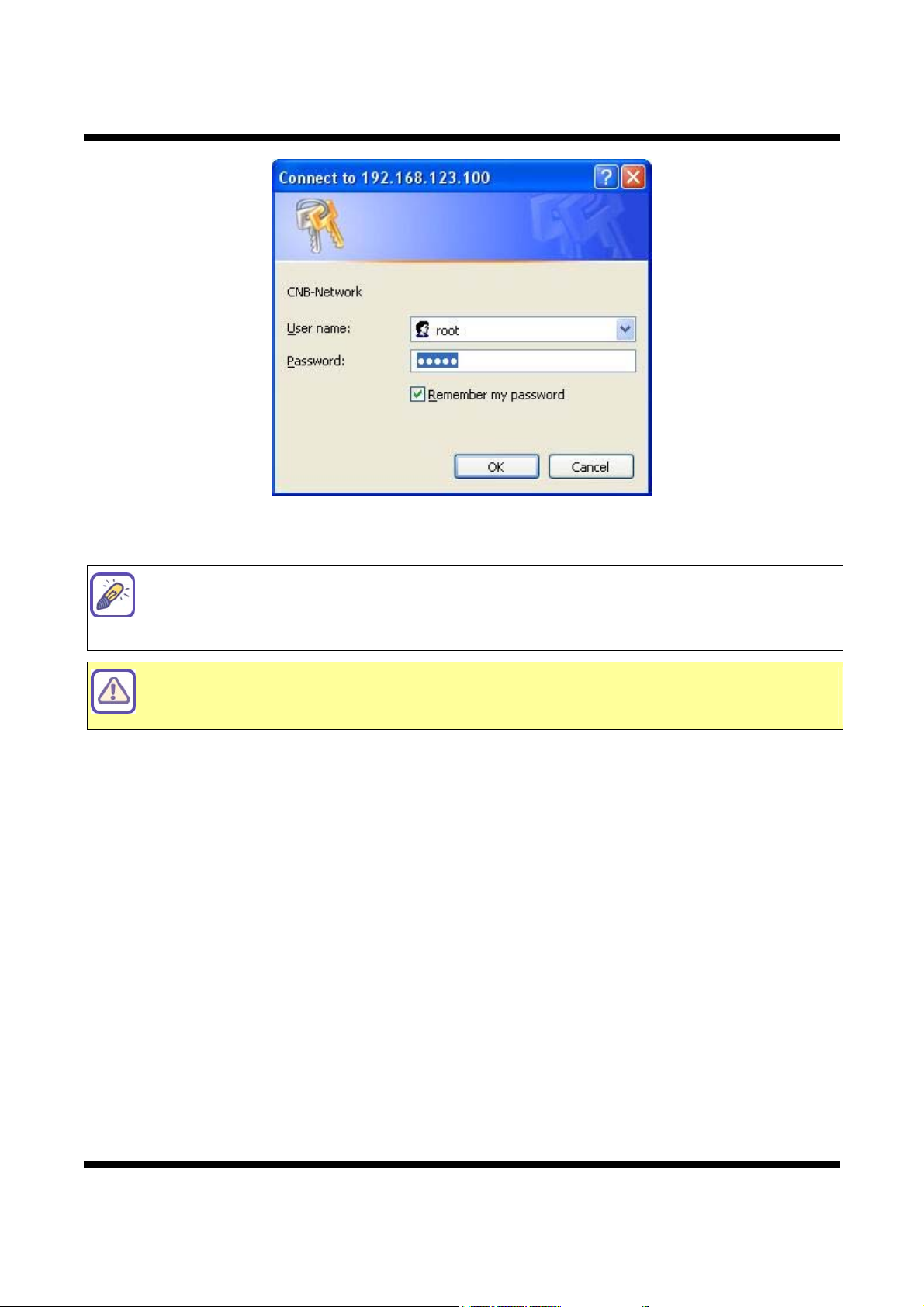
If you are logging in as an administrator, the Log-In box will appear as shown in [Figure 1-1].
Basic Setup page will appear when you enter id and password.
Enabling『Enable anonymous viewing』option at Users setup page allows users to
monitor Live view without a log-in prompt, however, accessing to other menu requires
a log-in prompt.
Please refer to [1.5. Configuring Users] for more details.
Once user login to network camera through Internet Explorer, it won’t ask user to login
again until username or password is modified. Thus, please close Network camera’s
Internet Explorer window for security after monitoring live view or modifying its setting
values.
5 / 54
Page 6
XNET User Manual
Figure 1-1 Log-in window
The default user name and password is “root” and “admin” respectively.
For security purpose, it is recommended to change the administrator’s id and password
from their default values. Please be careful not to forget them or expose them to
others.
Please refer to [1.5. Configuring Users] for detail.
If you forget the administrator’s password, 『Factory Reset』is the only way to regain
access. However, since t his will retrieve all default settings, you need to configure the
network settings using IP installer software again.
6 / 54
Page 7
XNET User Manual
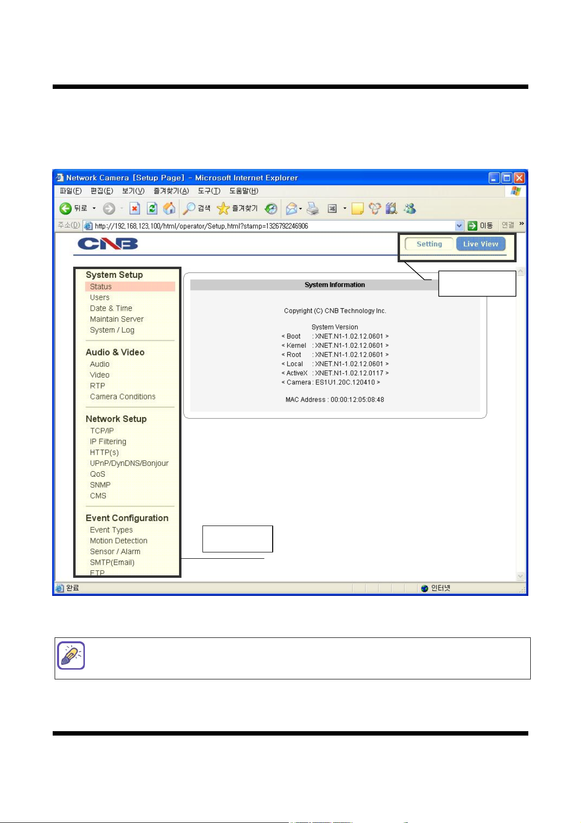
11..22.. CCoonnffiigguurriinngg CCaammeerraa
When you log in as an administrator, XNET’s Basic Setup page will appear as shown in [Figure 1-2].
Setup pages for different features can be accessed from this page. Access to each function is controlled by
different user groups. (Administrator, Operator, and Viewer)
Main Menu
Sub Menu
Figure 1-2 Basic Setup
Basic Setup Page can be accessed from Operator group level and up. If you want to
access Administrator level page in this user level, you need to log in as Administrator.
Please refer to the following table for access authority.
7 / 54
Page 8

XNET User Manual
● Accessible
▬ Not Accessible
Function
Access
Administrator Operator Viewer
Live View Page ● ● ●
Users Setup Page ●
▬ ▬
Date&Time Setup Page ● ●
Maintain Server Setup Page ●
System / Log Setup Page ●
▬ ▬
▬ ▬
Audio Setup Page ● ●
Video Setup Page ● ●
RTP Setup Page ● ●
Camera Condition
Setup Page
TCP / IP Setup Page ●
IP Filtering Setup Page ●
● ●
▬ ▬
▬ ▬
▬
▬
▬
▬
▬
HTTP(s) Setup Page ●
UPnP / DynDNS / BJR
Setup Page
●
QoS Setup Page ●
SNMP Setup Page ●
CMS Setup Page ●
Event Type
Setup Page
Motion Detection
Setup Page
Sensor / Alarm
Setup Page
● ●
● ●
● ●
SMTP Setup Page ● ●
FTP Setup Page ● ●
▬ ▬
▬ ▬
▬ ▬
▬ ▬
▬ ▬
▬
▬
▬
▬
▬
Diagram 1-1 User Access Authority
8 / 54
Page 9
XNET User Manual
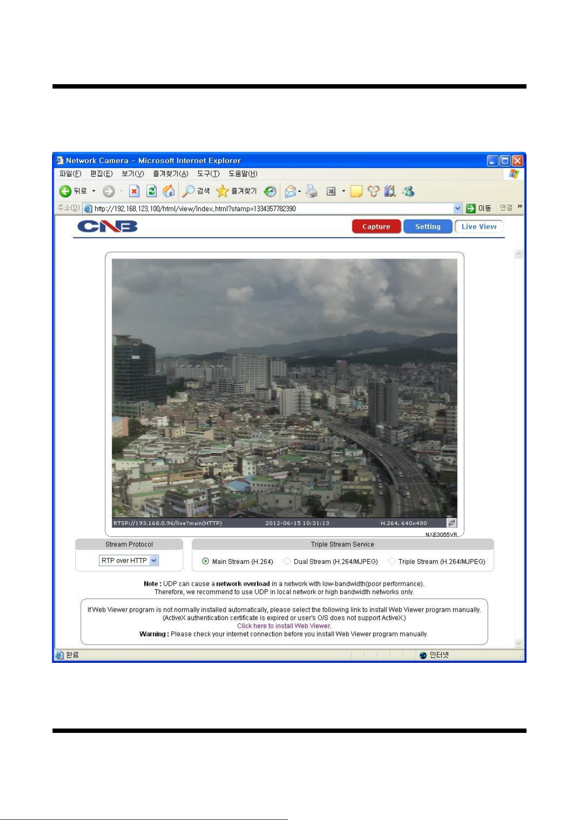
11..33.. WWeebb VViieewweerr ((IInnddeexx..hhttmmll))
When you access an XNET product, Web Viewer page will appear automatically. Viewer area displays the
video output from the camera, and menu bar contains taps that lead to each functional setting page.
Figure 1-3 Web Viewer
9 / 54
Page 10

XNET User Manual
ITEM DESCRIPTION
Capture -
Setting -
Live View -
Stream Protocol -
Captures the still image and displays on a pop-up window.
[Save to] c:₩xNetCapture
Opens up Basic setup Page.
Setup page for each XNET function can be opened from this Menu
screen.
(Please refer to [1.4. Status Window] for detail.)
Opens up Live index View Page.
Index View Page will display Video as well as setting up Stream
Protocol and Service.
A Stream Protocol can be selected when selecting Edit Box.
[RTP over UDP / RTP over TCP / RTP over HTTP /
RTP Multicast]
Triple Stream
Service
Main Stream When this box is checked, Main Stream Video is displayed.
When this box is checked, Dual Stream Video is displayed.
Dual Stream
(H.264/MJPEG) Dual-Codec needs to be enabled in Video Setup Page
in order to enable for Dual Stream Video to be displayed.
(Please refer to [1.10. Configuring Video] for detail.)
When this box is checked, Triple Stream Video is displayed.
Triple Stream
(H.264/MJPEG) Dual-Codec needs to be enabled in Video Setup Page
in order to enable for Triple Stream Video to be displayed.
(Please refer to [1.10. Configuring Video] for detail.)
10 / 54
Page 11
XNET User Manual
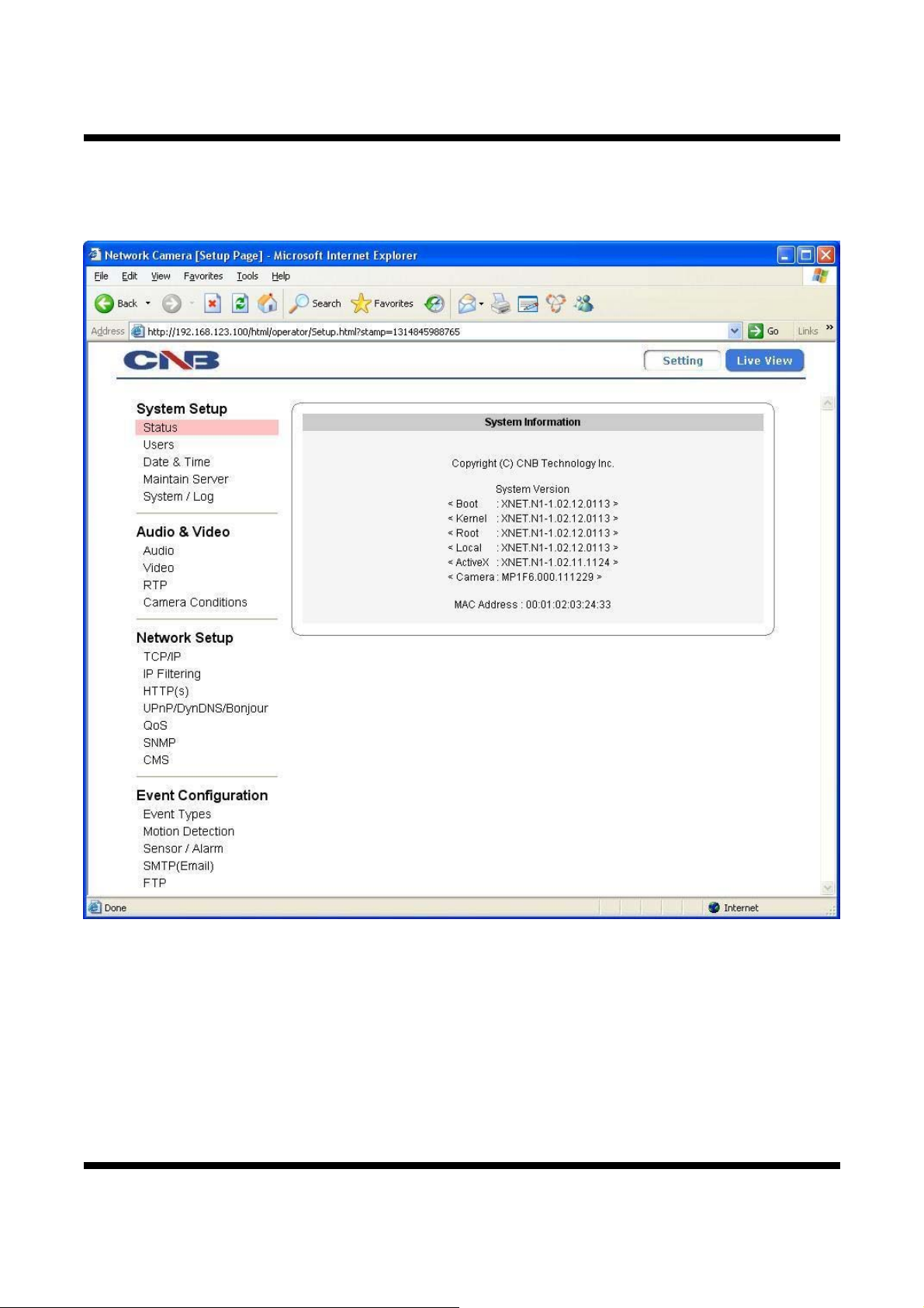
11..44.. SSttaattuuss WWiinnddooww
Status page displays XNET System’s Version, ActiveX, Camera Version and its Ethernet address.
Click [▷Status] button to open the page shown in [Figure 1-4].
Figure 1-4 Status Window
11 / 54
Page 12
XNET User Manual
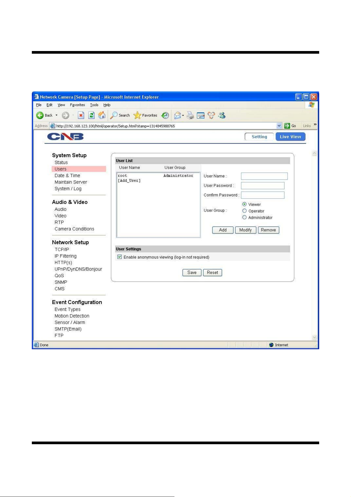
11..55.. CCoonnffiigguurriinngg UUsseerrss
This page shows “how to setup authority” to users for controlling Video and other functions of XNET system.
Click [▷Users] button to open the page shown in [Figure 1-5].
12 / 54
Figure 1-5 Users Configurations
Page 13
ITEM DESCRIPTION
User List -
Add -
XNET User Manual
Displays list of registered users.
"root" is the system’s administrator. "root" cannot be added or deleted.
Only the password for “root” can be changed.
This adds a new user.
Select [Add User] tap in『User List』Box. To add a new user, enter
『User name』,『Password』and『User group』then click【Add】
button.
Updated User list can be viewed in『User List』Box.
- Up to 10 users can be added.
-『User name』must start with alphabet and its length must be from 1
to 16.
-『Password』length must be from 1 to 8.
Administrator Full control of the XNET system.
Operator Refer to [Diagram 1-1]
Viewer View camera’s video signal only.
Modifies information for each user.
Modify -
Select a user in『User List』Box, enter new『Password』,『User
group』and click【Modify】button to save the changes.
Updated detail can be viewed in『User List』Box.
Removes a user.
Remove -
Select a user in『User List』Box and click【Remove】button to
remove.
Updated detail can be viewed in『User List』Box.
User Settings
Enable
anonymous
viewing
Turns Anonymous Viewer mode on or off.
When enabled, Web Viewer can be accessed without a log-in prompt.
Save - Applies and saves the configurations.
Reset - Recalls previously the saved configurations.
Please disable『Enable anonymous viewing』function if registered users at『User List』
only want to monitor network camera’s live view.
13 / 54
Page 14
XNET User Manual
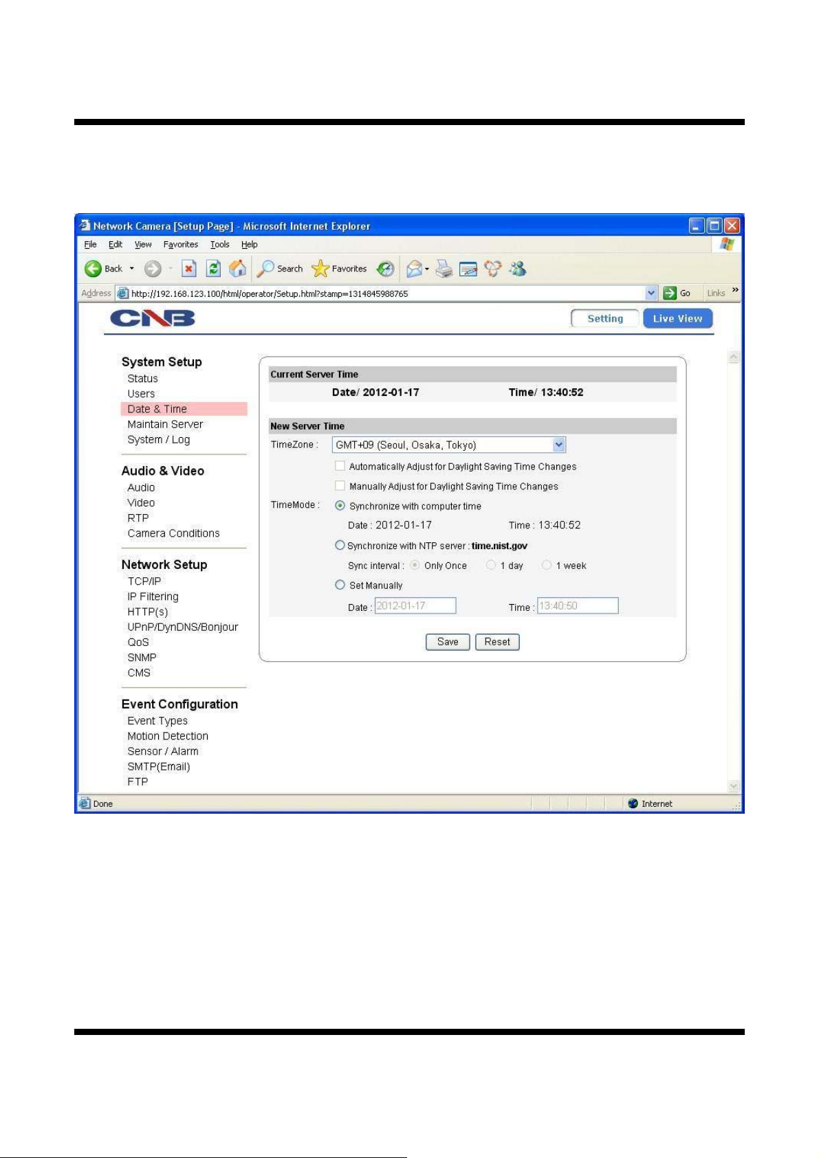
11..66.. CCoonnffiigguurriinngg DDaattee && TTiimmee
This page will change Date and Time of XNET system.
Click [▷Date & Time] to open the page shown in [Figure 1-6].
14 / 54
Figure 1-6 Date & Time Configurations
Page 15

XNET User Manual
ITEM DESCRIPTION
Current
Server Time
New
Server Time
- Displays time of XNET system.
Time Zone Selects Time Zone. <Default : GMT+09>
Automatically Adjust
for Daylight Saving
Time Changes
Manually Adjust for
Daylight Saving Time
Changes
Selects about the use of automatic adjustment for Summer Time.
(Daylight Saving Time).
Selects about the use of manual adjustment for Summer Time.
(Daylight Saving Time).
Sets Date and Time of the Server.
『Synchronize with computer time』
- Synchronizes time and date of Client PC to Server.
『Synchronize with NTP server』
- Synchronizes server’s time and date to NTP Server.
Time Mode
(Enter NTP Server address in Network Setup Page.)
- Set NTP Server update period.
Only Once No update periodically.
1 day Once a day.
1 week Once a week.
『Set Manually』
- Set date and time of Server manually.
Save - Applies and saves the configurations.
Reset - Recalls previously the saved configurations.
15 / 54
Page 16
XNET User Manual
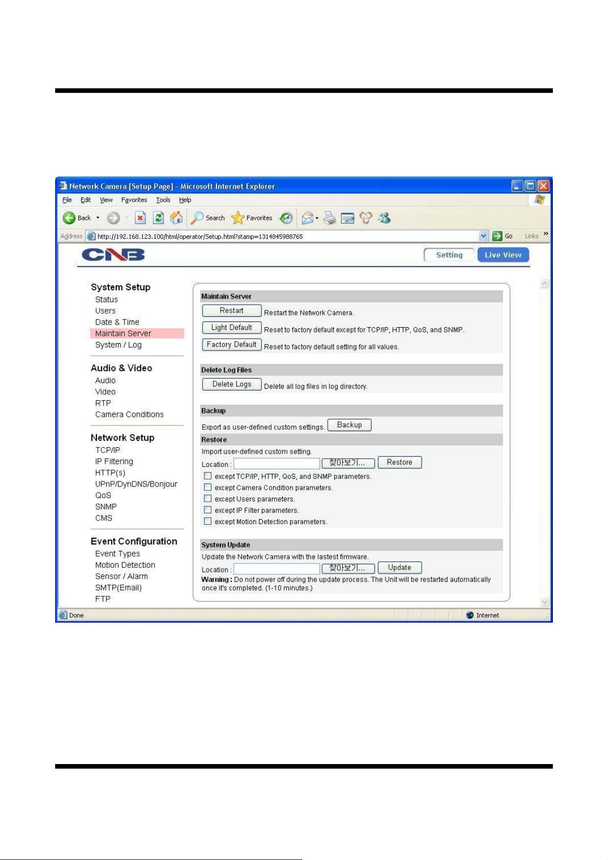
11..77.. CCoonnffiigguurriinngg MMaaiinnttaaiinniinngg SSeerrvveerr
This page configures system parameters such as system restart, factory default settings, system upgrade,
saving configurations, saving images, and other additional features.
Click [▷Maintain Server] to open the page shown in [Figure 1-7].
16 / 54
Figure 1-7 Maintaining Server Configurations
Page 17
XNET User Manual
ITEM DESCRIPTION
Restart Restarts the system. It takes about 45 seconds.
Maintain
Server
Light Default
Factory Default
Delete Log
Files
Delete Logs Delete all saved Log Messages.
Backup Backup
Restore Restore
Resets all parameters except for TCP/IP, HTTP, QoS, and SNMP
setting.
This will be followed by a 45 seconds system reset.
Resets all parameters to Factory Default setting.
This will be followed by a 45 seconds system reset.
This saves current camera’s configurations to Client PC as file
(xnetconfig.dat).
This loads up settings from a saved Backup file.
Click【Restore】button after selecting backup files in Client PC.
Optional check boxes can be used to select settings to be excluded
from the restore process.
『except TCP/IP, HTTP, QoS, and SNMP parameters』
『except Camera Condition parameters』
『except Users parameters』
『except IP Filter parameters』
System
Update
Upgrade
『except Motion Detection parameters』
This will be followed by a 45 seconds system reset.
Use this to update the system.
Select location of Update file in Client PC and click【Update】button.
This will be followed by 45 seconds system restart.
Upgrade File can be downloaded from http://www.cnbtec.com.
Please do not disconnect power and LAN cable from the
XNET while the upgrade is in process.
It might cause a system error.
17 / 54
Page 18

XNET User Manual
11..88.. CCoonnffiigguurriinngg SSyysstteemm // LLoogg
System / Log page provides network camera’s configuration, language and error information to users.
Click [▷System / Log] button to open the page shown in [Figure 1-8].
18 / 54
Figure 1-8 System / Log
Page 19

XNET User Manual
ITEM DESCRIPTION
System
Settings
System LED
Control
Language File
Upload
Language File
List
System
Overview
Displays current configurations for XNET option pages.
System LED Enable / Disable System LED.
Event LED Enable / Disable Event LED.
-
Upload language files.
Language File can be downloaded from http://www.cnbtec.com.
List Display the list of saved language files.
Set a language file to the system.
Set
Please select a language file from the list and then select【Set】
button to apply the language file to the system.
Web Page language will be modified to the set language.
Delete a language file from the list.
Please select a language file from the list and then select【Del】
Del
button to remove from the list.
If you delete the currently set language file from the list, then web
page language is set to the default language – English.
Log Report
Log List Display the list of currently saved Log files.
Loads up Log Messages file stored in the network camera.
Load List
Log Message file can be sorted by date and index.
Click【Load List】button to view message list in the Log List.
Logs View
Logs Del
Select a file from the『Log List』and click【Logs View】button to
view. (or Double Click)
Select a file from the『Log List』and click【Logs Del】button to
delete.
Click【Save Logs】button to save the Log file to PC.
Save Logs
The log file is saved to PC as a TAR and GZIP file format (*.tgz) and
it can be also downloadable from the network camera’s FTP server.
19 / 54
Page 20

XNET User Manual
11..99.. CCoonnffiigguurriinngg AAuuddiioo
XNET’s Audio features can be configured in this page.
Click [▷Audio] button to open the page shown in [Figure 1-9].
20 / 54
Figure 1-9 Audio Configurations
Page 21

ITEM DESCRIPTION
Audio Control Enable audio Enables / Disables Audio feature. <Default : Disable>
XNET User Manual
Source
Audio Input
Encoding
Save - Applies and saves the configurations.
Reset - Recalls previously the saved configurations.
Set Audio source.
[Microphone | Line]
Set Audio codec.
[G.711 (A-Law) | G.711 (U-Law)]
21 / 54
Page 22

XNET User Manual
11..1100.. CCoonnffiigguurriinngg VViiddeeoo
XNET’s Video features can be configured in this page.
Click [▷Video] button to open the page shown in [Figure 1-10].
22 / 54
Figure 1-10 Video Configurations
Page 23

XNET User Manual
ITEM DESCRIPTION
Select a resolution of main stream video.
Resolution
[QVGA | CIF | VGA | D1 | XGA | 720P | SXGA (1280x960) | SXGA
(1280 x 1024) | 1080P]
Main Stream
(H.264)
Enable
Dual-Codec
Enable Triple-
Codec
Frame rate
Bit Control
Bit rate
(CBR)
Bit rate : Max
(VBR)
Codec
Turns Dual Stream feature on or off. <Default : Disable>
Dual Stream output is in H.264 & MJPEG Codec.
When configuring, select Main or Dual Stream in the Live View page.
Turns Triple Stream feature on or off. <Default : Disable>
Triple Stream output is in H.264 & MJPEG Codec.
When configuring, select Main/ Dual/Triple Stream in the Live View
page.
Selects Frame rate of Video.
[NTSC : 1 ~ 30 fps]
[PAL : 1 ~ 25 fps]
Select Bitrate mode.
[CBR / VBR]
Select CBR bitrate between 64kbps and 10Mbps depending on Main
Stream’s resolution.
Select VBR max bitrate between 64kbps and 10Mbps depending on
Main Stream’s resolution.
Select Video Codec.
[H.264 | MJPEG]
Dual Stream
(H.264 / MJPEG)
Resolution
Frame rate
Bit Control
(H.264)
Bit rate
(H.264 &
CBR)
Bit rate : Max
(H.264 &
VBR)
Quality
(MJPEG)
Select a resolution of dual stream video among QVGA | CIF | VGA |
D1 | XGA | 720P depending on Main Stream’s resolution.
Select Frame rate of Video.
[NTSC : 1 ~ 30 fps]
[PAL : 1 ~ 25 fps]
Select Bitrate mode.
[CBR / VBR]
Select CBR bitrate between 64kbps and 5Mbps depending on Dual
Stream’s resolution.
Select VBR max bitrate between 64kbps and 5Mbps depending on
Dual Stream’s resolution.
Select MJPEG’s video quality between 10 and 100.
23 / 54
Page 24

XNET User Manual
ITEM DESCRIPTION
Triple Stream
(H.264/MJPEG)
Codec
Resolution
Frame rate
Bit Control
(H.264)
Bit rate
(H.264 &
CBR)
Bit rate : Max
(H.264 &
VBR)
Quality
(MJPEG)
Select Video Codec.
[H.264 | MJPEG]
Select a resolution of triple stream video among QVGA | CIF | VGA |
D1 depending on Main Stream’s resolution.
Select Frame rate of Video.
[NTSC : 1 ~ 30 fps]
[PAL : 1 ~ 25 fps]
Select Bitrate mode.
[CBR / VBR]
Select CBR bitrate between 64kbps and 3Mbps depending on Dual
Stream’s resolution.
Select VBR max bitrate between 64kbps and 3Mbps depending on
Dual Stream’s resolution.
Select MJPEG’s video quality between 10 and 100.
Video Out
Mobile View
Reset
Save
Turns the Video Out feature on or off.
Enable Video
Out
Video Format
In case of Video Out funtion enable, WDR feature can’t
use In the Camera Condition Page.
Selects Video format at Video Out terminal between NTSC and PAL.
<Default : Enable>
Select Mobile stream.
[None | Dual Stream | Triple Stream]
-
This function can use when the codec of Dual or Triple
Stream is MJPEG.
- Applies and saves the configurations.
- Recalls previously the saved configurations.
24 / 54
Page 25

11..1111.. CCoonnffiigguurriinngg RRTTPP
RTP / RTSP / Multicast protocol ports and IP address can be configured in the page.
Click [▷RTP] button to open the page shown in [Figure 1-11].
XNET User Manual
Figure 1-11 RTP Configurations
25 / 54
Page 26

XNET User Manual
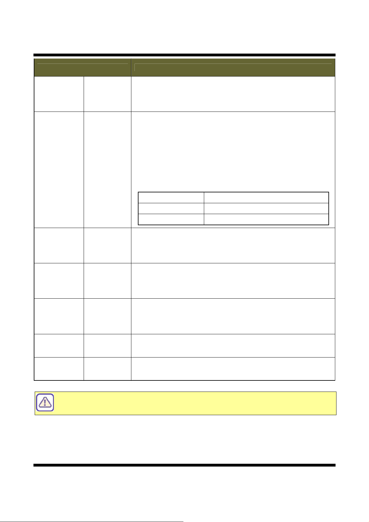
ITEM DESCRIPTION
RTSP
Configuration
RTP
Configuration
RTSP Port
RTP Start Port
RTP End Port
Maximum
number of
users to
connect
Enter RTSP Port of the Main Stream between 1 and 66535.
<Default : 554>
Enter RTP Start Port between 1024 and 65435. <Default : 2000>
The minimum difference between RTP Start and End Port should be
100.
Enter RTP End Port between 1124 and 65535. <Default : 3000>
The minimum difference between RTP Start and End Port should be
100.
Enter the maximum allowable number of users connected to the
Stream between 1 and 10. However, it can be very depending on Main
Stream’s Bitrate.
Maximum number of users to connect = 16Mbps / Main Stream’s
bitrate. (1<= Maximum number of users to connect <=10)
Bitrate Number of users to connect
9M ~ 10M 1 people
6M ~8M 2 people
5M 3 people
4M 4 people
3M 5 people
2M 8 people
64K ~ 1M 10 people
TTL Value Enter TTL value for outgoing multicast between 1 and 255.
1st Address Enter the destination IP address of Main Stream.
2nd Address Enter the destination IP address of Dual Stream.
Multicast
Configuration
3rd Address Enter the destination IP address of Triple Stream.
Video Port Enter Video Port between 1124 and 65535. <Default : 49990>
Audio Port Enter Audio Port between 1124 and 65535. <Default : 49992>
Save - Applies and saves the configurations.
Reset - Recalls previously the saved configurations.
26 / 54
Page 27

11..1122.. CCoonnffiigguurriinngg CCaammeerraa CCoonnddiittiioonnss
This shows how to setup the camera functions of the XNET products.
Click [Camera Condition] button to open the page shown in [Figure 1-12].
XNET User Manual
Figure 1-12 Camera Condition Configurations
27 / 54
Page 28

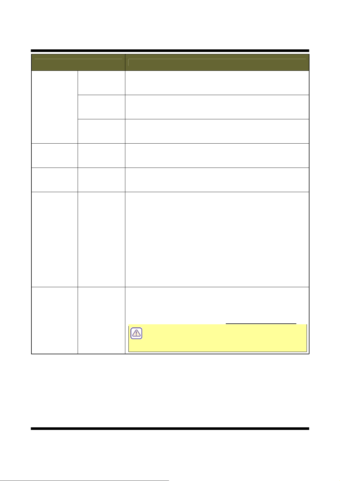
XNET User Manual
ITEM DESCRIPTION
OSD Menu
Control
White Balance
OSD Menu
Control
Menu On
Menu Off
▲, ▼, ◀, ▶
White Balance
Enable / Disable OSD menu function.
Display OSD Menu on Viewer.
[Keyboard shortcut : Ctrl + 1]
Hide OSD Menu on Viewer.
[Keyboard shortcut : Ctrl + 3]
Move OSD key on Viewer.
[Keyboard shortcut : Top (Ctrl + 8), Bottom(Ctrl + 2),
Left (Ctrl + 4), Right (Ctrl + 6)]
Configures Video’s White Balance.
White Balance means balancing color temperature by adjusting Red
and Blue level. As needed, select an item on this menu among ATW,
Manual, Preset.
ATW (Indoor) Adjusts White Balance automatically as the
proper value for indoor environment.
ATW (Outdoor) Adjusts White Balance automatically as the
proper value for outdoor environment.
Manual Adjusts White Balance level manually according
to the value of the configured Red and Blue
level.
Push Adjusts White Balance automatically as the
proper value by clicking【Set】button.
Video Setting
Color Temp
Red Gain
Blue Gain
Color Gain
Day Sharpness /
Night Sharpness
ACE
Select among Low, Moddle, and High for Color Temperature.
This can only be enabled when White Balance is configured as
Manual mode.
Select the value of Video’s Red level between 0 and 20.
This can only be enabled when White Balance is configured as
Manual mode.
Select the value of Video’s Blue level between 0 and 20.
This can only be enabled when White Balance is configured as
Manual mode.
Select Color Saturations of Video between 0 and 20.
Select the value for Sharpness depending on the illuminance.
Select among values from 0 to 20.
Day Sharpness : a sharpness value for cameras on the place
of high illuminance
Night Sharpness : a sharpness value for cameras on the place
of low illuminance
Select among Off, Low, Middle, and High for Camera’s ACE.
28 / 54
Page 29

XNET User Manual
ITEM DESCRIPTION
Exposure
Setting
Gamma
Day/Night
Day/Night Level
Day/Night Delay
Lens Type
Brightness
DC Level
CET WGT
AGC
Flickerless
Select the Gamma value of Video between 0.35 and 1.00
Switch the mode related to the Day/Night.
Select among Auto, Color, B/W and Intelligent.
Select the Level generated by a switch of Day/Night mode.
Select among Low, Middle, and High.
Select the Delay Time generated by a switch of Day/Night mode.
Select among values from 3 to 20.
Select the Lens Type between Electronic and DC.
Select a proper value for brightness of recorded display.
This can only be enabled when Lens Type is configured as DC mode,
Indoor mode.
You can choose it among values from 0 to 20.
Select the DC level value of Video between 0 and 20.
Select the CET WGT value of Video between 0 and 20.
Select the Gain value of Video between 0 and 20.
Select On or Off for reducing Camera’s flickering.
Special
Setting
DSS
Shutter Speed
Mode
BLC / WDR
Select DSS between Off / x2 / x3 / x4.
Configures Camera’s Shutter Speed.
(A minimum value is recommended.)
High Shutter Speed can capture a quick movement accurately, but
Video gets noisy while it tries to maintain brightness level properly.
Low Shutter Speed reduces Video Noise, but it will not catch quick
movement very well.
This can only be enabled when Lens Type is configured as DC mode.
Select Indoor or Outdoor for Lens mode.
This can only be enabled when Lens Type is configured as DC mode.
Configures about the BLC function and the WDR function.
(BLC: BackLight Compensation, WDR: Wide Dynamic Range)
In case of using the BLC function, a damaged image from backlight
can be compensated.
In case of using the WDR function, it provides clear images even
under backlight circumstances where intensity of illumination can
vary excessively when there are both very bright and very dark areas
simultaneously in the field of view of the camera.
It is available to select among Off | WDR | BLC.
In case of WDR mode use, Video Out function can’t use
in Video Page.
29 / 54
Page 30

XNET User Manual
ITEM DESCRIPTION
Condition
Initialization
Save
WDR WGT
2D-DNR
3D-DNR Day
3D-DNR Night
Mirror
Time & Date
Display
OSD Font Size
Reset Camera
-
Configures WDR Level between 1 and 7.
Select Two-Dimensional Noise Reduction from 0 up to 20.
Select Three-Dimensional Day Noise Reduction from 0 up to 20.
Select Three-Dimensional Night Noise Reduction from 0 up to 20.
Select among Off / Horizontal / Vertical / Rotation.
Select Time & Date display between On and OFF.
The TimeMode of Date & Time Page can use to maintain
Date & Time synchronization.
Sets the font size used on the OSD menu.
You can choose it between numbers from 1 to 4.
Initializes the Camera’s Condition parameters.
Applies and saves the configurations.
Reset
-
Recalls previously the saved configurations.
30 / 54
Page 31

11..1133.. CCoonnffiigguurriinngg TTCCPP // IIPP PPaarraammeetteerrss
This configures XNET’s network related parameters.
Click [▷TCP / IP] button to open the page shown in [Figure 1-13].
XNET User Manual
Figure 1-13 Network Configurations
31 / 54
Page 32

XNET User Manual
ITEM DESCRIPTION
IP Address
Configuration
Obtain an
IP Address
automatically
(DHCP)
IP address
Subnet mask
Turns DHCP on or off.
Check DHCP checkbox to get an IP address automatically from the
network using DHCP protocol.
Obtained IP address can be viewed by IP Installer.
If the network does not use DHCP server, the product
will wait for server’s response for two minutes and
restart with its previous IP address (192.168.123.100).
Please modify Camera’s IP address with IP Installer
program.
Enter an IP address.
Configure IP address after checking IP address range configuration of
the router where the XNET product is connected.
Enter Subnet mask.
Use this when you want to access only from the same subnet by
masking out upper portion of the IP address.
Use 255.255.255.255 when you want to connect from one PC only.
DNS
Configuration
NTP
Configuration
Host name
Configuration
Default
Gateway
Primary
DNS Server
Secondary DNS
Server
NTP Address
User
the Host name
Enter the address of Default Gateway.
Enter primary DNS address.
Enter secondary DNS address.
Enter address of NTP (Network Time Protocol Server).
NTP server is used when『Synchronize with NTP Server』is selected
in Date & Time page.
Enter Host Name.
MAC Clone Enter Ethernet Address.
MAC Address
Reset MAC
Address
Initializes the Camera’s Ethernet Address.
Save - Applies and saves the configurations.
Reset - Recalls previously the saved configurations.
32 / 54
Page 33

11..1144.. CCoonnffiigguurriinngg IIPP FFiilltteerriinngg
This configures IP Filters for XNET product.
Click [▷IP Filtering] button to open the page shown in [Figure 1-14].
XNET User Manual
Figure 1-14 IP Filtering Configurations
33 / 54
Page 34

XNET User Manual
ITEM DESCRIPTION
IP Filter
Address List
List Displays list of currently established IP Filters.
Adds an IP address to filter out.
Enter the IP address and click【Add】button to add it to『IP Address
List』Box.
Add
The updated list can be viewed in『IP Address List』Box.
- Up to 20 IP addresses can be added.
- Duplicate IP address, Location Hostname, Default Router, Subnet
Mask, DNS1 and DNS2 can not be inputted.
Removes an IP address from『IP Address List』Box.
Remove
Select the IP address to remove and click【Remove】button to
remove it from the list.
The updated list can be viewed in『IP Address List』Box.
Enable
IP Filtering
Turns the IP Filter on or off.
Select IP Filtering Mode between accept and block.
IP Filter
Enable
IP Filtering
Mode
This can select between Accept | Drop when『Enable IP Filtering』
turned on.
In Accept Mode, XNET product will be accessed from the IP addresses
in『IP Address List』box.
In Drop Mode, XNET product will not be accessed from the IP
addresses in『IP Address List』box.
Save - Applies and saves the configurations.
Reset - Recalls previously the saved configurations.
In case of using IP Filter Accept function, Please need to remember IP addresses in『IP
Address List』Box.
Must restore to the original state from H/W Factory Reset because can’t connect in web
page when Accept IP addresses does not remember.
34 / 54
Page 35

11..1155.. CCoonnffiigguurriinngg HHTTTTPP((ss))
This configures HTTP(s) port to access XNET’s webpage.
Click [▷HTTP(s)] button to open the page shown in [Figure 1-15].
XNET User Manual
Figure 1-15 HTTP(s) Configurations
35 / 54
Page 36

XNET User Manual
ITEM DESCRIPTION
Enter HTTP Port to access the webpage between 1 and 65535. <Default :
80>
Any other port number has to be entered at the end of the IP address
when accessing.
HTTP
HTTP
Port
e.g. When using HTTP Port 8080, enter http://192.168.123.100:8080
Enter HTTPS Port to access the webpage between 1 and 65535.
<Default : 443>
Any other port number has to be entered at the end of the IP address
when accessing.
HTTPS
HTTPS
Port
e.g. When using HTTPS Port 444, enter https://192.168.123.100:444
Save - Applies and saves the configurations.
Reset - Recalls previously the saved configurations.
36 / 54
Page 37

XNET User Manual
11..1166.. CCoonnffiigguurriinngg UUPPnnPP // DDyynnDDNNSS // BBoonnjjoouurr
UPnP is a protocol for IP installer software. You can enable or disable this UPnP, and you can also use a
Friendly Name.
DynDNS configures XNET’s DDNS server information.
Click [▷UPnP / DynDNS / Bonjour] button to open the page shown in [Figure 1-16].
Figure 1-16 UPnP / DynDNS / Bonjour Configurations
37 / 54
Page 38

XNET User Manual
ITEM DESCRIPTION
UPnP
Settings
DynDNS
Settings
Enable UPnP
Enable / Disable UPnP.
When enabled, you can use IP Installer’s XNET Auto Search feature.
Friendly Name Enter UPnP’s Friendly Name.
Enable / Disable DynDNS.
Enable DynDNS
When enabled, you can automatically obtain a domain from DDNS
server by simply registering the XNET product.
Enable / Disable DynDNS Anonymous feature.
When enabled, DDNS service is used without going through
Enable
Anonymous
authentication at autoipset.com DDNS server.
If you want to register a hostname with a specific user account at
autoipset.com server, Please make an account from
http://www.autoipset.com.
Enter a Host Name for the DynDNS server.
Alias host name
Host Name can not be more than 32 characters when you register it
at autoipset.com.
User name Enter a User Name for the DynDNS server.
Password Enter a password for the DynDNS server.
Enable Bonjour
Bonjour
Enable / Disable Bonjour.
When enabled, you can use IP Installer’s XNET Auto Search feature.
Settings
Server name Enter Bonjour’s Server Name.
Save - Applies and saves the configurations.
Reset - Recalls previously the saved configurations.
38 / 54
Page 39

XNET User Manual
11..1177.. CCoonnffiigguurriinngg QQooSS
QoS means the protocol controlling transmission rates and error rates over the internet/network to
guarantee the service quality. This configures the video and alarm items related to QoS.
Click [▷QoS] button to open the page shown in [Figure 1-17].
Figure 1-17 QoS Configurations
39 / 54
Page 40

XNET User Manual
ITEM DESCRIPTION
Enable QoS Enables / Disables QoS.
Guarantees the quality of the service related to the video by reading the
proper value for reaching a certain standard. Besides, the value of this item
also can be used for deciding the order of priority through the way to
compare with those of the Alarm DSCP item.
Video DSCP
If this value is bigger than those of the Alarm DSCP item, it
QoS
means that work related to the Video DSCP is prioritized.
Normally, the Video DSCP item has priority.
Guarantees the quality of the service related to the alarm by reading the
proper value for reaching a certain standard. Besides, the value of this item
also can be used for deciding the order of priority through the way to
Alarm DSCP
compare with those of the Video DSCP item.
If this value is bigger than those of the Video DSCP item, it
means that work related to the Alarm DSCP is prioritized.
Save - Applies and saves the configurations.
Reset - Recalls previously the saved configurations.
40 / 54
Page 41

XNET User Manual
11..1188.. CCoonnffiigguurriinngg SSNNMMPP
SNMP means the protocol for administration about the network by collecting related information
automatically from the each host over the network based on TCP/IP. This configures information related to
SNMP.
Click [▷SNMP] button to open the page shown in [Figure 1-18].
Figure 1-18 SNMP 페이지 (SNMP 설정)
41 / 54
Page 42

XNET User Manual
ITEM DESCRIPTION
Enable SNMP Enables / Disables SNMP.
SNMP
SNMP Trap
Read
Community
Write
Community
Location
Contact
Sets the keyword for right to read only when accessing to SNMP. Up to 64
letters(alphabets/arabic numerals) are available.
Sets the keyword for right to write only when accessing to SNMP. Up to 64
letters(alphabets/arabic numerals) are available.
Sets information on the system's location available to read and write. Up to
46 letters(alphabets/arabic numerals) are available.
Saves the email address available to contact about the system. Up to 46
letters(alphabets/arabic numerals) are available.
SNMP Port Enter the SNMP port, default SNMP port is 161.
Enable SNMP
Trap
Enables / Disables SNMP Trap.
Traps are used by the camera to send periodic messages to a
management system as a Heartbeat.
Trap Port Enter the SNMP trap port, default SNMP port is 162.
Trap Address Enter the IP address of the management server.
Trap
Community
Community to use when sending a trap message to the management
system.
Save
Reset
42 / 54
Trap Interval Interval between two traps in seconds.
- Applies and saves the configurations.
- Recalls previously the saved configurations.
Page 43

11..1199.. CCoonnffiigguurriinngg CCMMSS
This configures XNET’s CMS Server information.
Click [▷CMS] button to open the page shown in [Figure 1-19].
XNET User Manual
Figure 1-19 CMS Configurations
ITEM DESCRIPTION
CMS CMS Port
Save - Applies and saves the configurations.
Reset - Recalls previously the saved configurations.
Enter CMS Port number for communication with CMS between 1 and
65535. <Default : 5000>
43 / 54
Page 44

XNET User Manual
11..2200.. CCoonnffiigguurriinngg EEvveenntt TTyyppee
This is related to XNET’s DDNS Server information.
Click [▷Event Types] button to open the page shown in [Figure 1-20].
Figure 1-20 Event Configurations
Before executing the events, make sure to check the following items on the pages of
Video and RTP:
• Bite rate(H.264 codec: Bit rate, MJPEG codec: Quality)
• Maximum number of users to connect
• Resolution
The operation of XNET Web browsers can be slow when the events are being executed
on surroundings using as high specifications of the items above.
Please refer to this manual's explanations for the Video and RTP page, for more details.
44 / 54
Page 45

XNET User Manual
ITEM DESCRIPTION
Event
Enable
Event Mode
Event
Settings
Enable Event Enable / Disable event processing.
Sensor Enable / Disable the Alarm Sensor.
Motion
Detection
Network
Linkdown
Alarm output
port
Enable / Disable Motion Detection.
Enable / Disable Network Linkdown.
Please use after『Save image to SD Memory』enabled.
This sends out Alarm signal to its output port during event
processing.
Select saved stream when processing an event.
Capture
Stream
<Default : Main Stream>
When Dual-Codec enabled, you can select Dual Stream.
When Triple-Codec enabled, you can select Triple Stream.
Capture
Format
Capture
Frame
(MJPEG)
Display stream format of selected Capture Stream.
Configure saved frame among 1 / 2 / 3 when processing an
event.
Event
Output
Pre-Alarm
Post-Alarm
Upload image
to FTP
Send Image
to Email
Save image
to SD
Memory
When processing an event, this establishes saving images or
video before the occurrence of the event.
It can be saved MAX 5 seconds before the event.
When processing an event, this establishes saving images or
video after the occurrence of the event.
It can be saved MAX 8 seconds before the event.
This allows Alarm images or video to be uploaded to an FTP
server when processing an event.
The client PC has to run FTP server to receive the images or
videos, and the information of the FTP server has to be
accurately entered and saved at the FTP Configuration page.
This allows Alarm images (Not Video) and time information
message When processing an event.
Only on images file at the moment of the event gets the
image out via e-mail.
The e-mail address has to be accurately entered and saved
at SMTP configuration page.
This allows Alarm images to be saved to SD card when
processing an event.
This flag must be sure to check “disable” state when SD
Memory card remove.
45 / 54
Page 46

XNET User Manual
Load saved
images
Load Saved images through internal FTP Server.
View
Port Configure internal FTP Server Port between 1 and 65535.
Save - Applies and saves the configurations.
Reset - Recalls previously the saved configurations.
The saving of SD Card will remove the past captured Image or Movie files about total
20% of SD Memory Card when exceed over 94% of SD Memory Card for occurring event.
In case of SD Card, It support MAX 32G and recommend over Class 4.
e.g. 1080p, 4Mbps, 30fps, H.264, Pre 2 seconds + Post 3 seconds :
It will save about 750MB hourly when use SD Card 16G Class 6.
Event can be ignored about occurred event during SD Memory Card save high size of
Image or Movie files.
Also, FTP & SMTP can be missed the occurred events next time when Network is
unstable.
e.g. High size of Image or Movie? High Resolution, High Bitrate, etc…
46 / 54
Page 47

XNET User Manual
11..2211.. CCoonnffiigguurriinngg MMoottiioonn DDeetteeccttiioonn aarreeaa
This defines areas that detect motion and up to three different areas can be defined in each channel.
Click [▷Motion Detection] button to open the page shown in [Figure 1-21].
Figure 1-21 Motion Detection Area Configurations
47 / 54
Page 48

XNET User Manual
ITEM DESCRIPTION
AREA
Displays the current area of defined Motion Detection area.
When an area is selected from the list, its defined area gets displayed
and highlighted in viewer window.
Up to 3 motion detection area can be defined.
Show Selected Area
Caption Enter designation for each area.
Sensitivity
Defining Motion Detection
Area
Event Status Display occurred event information.
When this is checked, only the selected area gets displayed in viewer
window.
Sets sensitivity for detecting motions, “1” being the least sensitive and
“10” being the most sensitive.
The user needs to configure this according to their
applications and circumstances.
1. Enter a designation in the caption bar and set sensitivity.
2. Click【New】button.
3. A square with the designation you’ve just defined will appear in
viewer window.
4. The size of the square can be adjusted by clicking and dragging its
lower right cornet and the position can be adjusted by dragging the
square.
5. Click【Save】button once you are done defining the areas.
48 / 54
Page 49

11..2222.. CCoonnffiigguurriinngg SSeennssoorr // AAllaarrmm
This configures XNET’s Sensor / Alarm control.
Click [▷Sensor / Alarm] button to open the page shown in [Figure 1-22].
XNET User Manual
Figure 1-22 Sensor / Alarm Configurations
49 / 54
Page 50

XNET User Manual
ITEM DESCRIPTION
Sensor
Setting
Alarm
Setting
Signal Type
Hold Up Time
Selects the signal type for Alarm Input Port between Normally Close
and Normally Open.
Configures interval of repeating Alarm Out signals between 1 and 120
seconds.
Select the Alarm Control type either Auto or Manual.
Force
Alarm
Control
Off Control
In case of ‘Auto’ and ‘Manual’: Rings the alarm automatically during
the out interval depending on the Alarm Input Signal Type. But, in
case of ‘Manual’, user can ring or stop the alarm manually without
regard for time when using the Alarm button on the Live View page.
Save - Applies and saves the configurations.
Reset - Recalls previously the saved configurations.
50 / 54
Page 51

XNET User Manual
11..2233.. CCoonnffiigguurriinngg SSMMTTPP
This configures mailing out method of Alarm Images once ‘event’ occurred in the XNET system.
Click [▷SMTP] button to open the page shown in [Figure 1-23].
Figure 1-23 SMTP Configurations
51 / 54
Page 52

XNET User Manual
ITEM DESCRIPTION
Enable
Internal SMTP
Server
Enable POP3
Authorization
Turns Internal SMTP Server on or off.
When this box is checked, Alarm Image gets mailed out through an
internal mail server.
When this box is unchecked, Alarm Image gets mailed out through an
external mail server.
In case of external mail server, Mail Authentication, port, user,
password, address and etc needs to be configured.
Turns POP3 on or off when use external mail server and don’t use
SMTP Authorization.
When this box is checked, Server Name and Port needs to be
configured and SMTP.
Sender :
SMTP
Settings
POP3 Server
Name
POP3 Server
Port
Enable
SMTP
Authorization
Enter the name of POP3 server.
Enter the port number for POP3 server between 1 and 65535.
Turns External SMTP Server on or off.
When this box is checked, Mail Authentication, Server Name and
Server Port need to be configured.
Select one of the secure connection type based on the SMTPS
Secure
Connection
server’s configuration. By using TLS/SSL or STARTTLS all the
network packets between camera and server will be secured, hence
these types are recommended. [Never | TLS/SSL | STARTTLS]
Auth
Mechanism
SMTP Server
Name
SMTP Server
Port
Select one of the Authentication Mechanism based on the SMTP
server’s configuration.
[LOGIN | PLAIN | CRAM-MD5 | DIGEST-MD5]
Enter the server name of external mail server.
Enter the port number for external mail server between 1 and 65535.
User name Enter the user name of the external mail server.
Receiver :
E-mail
Address
Setting
Save
Reset
52 / 54
User
Password
Email Address
1 - 3
- Applies and saves the configurations.
- Recalls previously the saved configurations.
Enter the password of the external mail server.
Enter the e-mail address of the external mail server user.
User can input up to Max 3 E-mail address.
Page 53

XNET User Manual
11..2244.. CCoonnffiigguurriinngg FFTTPP
This configures how the Alarm Images get sent out using FTP once ‘event’ occurred in the XNET system.
Click [▷FTP] button to open the page shown in [Figure 1-24].
Figure 1-24 FTP Configurations
53 / 54
Page 54

XNET User Manual
ITEM DESCRIPTION
FTP
Server
FTP Name
Enter the address of the FTP server to send Alarm Images or Movies
to in the event processing.
The client PC at that IP address has to run the FTP server in order to
receive the Alarm Images.
FTP Port
User Name
Login
Information
Password
Enter the port number for the FTP server between 1 and 65535 to
send Alarm Images or Movies to in the event processing.
Enter the user name of the FTP server to send Alarm Images or
Movies to in the event processing.
Enter the password of the FTP server to send Alarm Images or Movies
to in the event processing.
Save - Applies and saves the configurations.
Reset - Recalls previously the saved configurations.
54 / 54
 Loading...