

Page 1
PROGRAMMING MANUAL
( G codes type A )
Manual supplied with
CMZ CNC LATHES
Models
(for all machines)
The basic preventive information contained in the manual should be observed in order to
ensure a safe operation of the machine. The operator should thoroughly read this manual
before operating the machine.
Keep this manual at hand reach in a safe location.
Page 2

Issue 07.2004
Valid for
TL-15 from machine 368
TL-20 from machine 368
TL-25 from machine 368
TB-46 from machine 123
TB-67 from machine 123
TBI520 from machine 556
The machine includes more functions that those described in this
manual. However, the purchaser will have not the right of
demanding any of these additional functions at the time the
machine is supplied or when serviced by our After-sales Service.
CMZ reserves the right of making technical changes without
previous notice.
No part of this manual may be transmitted or copied, in any form or
by any means, without the previous written permission of CMZ.
Infringers will be prosecuted and claims for damages will be
lodged. Al rights reserved, particularly in case of Patent or Utility
Model.
© C.M.Z. , S.A. 2004 All Rights Reserved
Page 3
PROGRAMMING MANUAL -3-
EXAMPLE
COMMAND
MEANING OF SYMBOLS
Several symbols are used to indicate the various types of warning or advise.
The operator must know the meaning of these symbols and carefully read the instructions
enclosed in order to ensure a safe operation of the machine.
<Symbols related to warning messages>
The instructions provided are classified into three categories: DANGER, WARNING and
CAUTION
The following symbols are used to indicate the hazard level:
Indicates an imminent hazard that, if not prevented, will be cause
of death or serious injures.
The instructions contained in DANGER boxes must be strictly
observed.
Indicates a potentially hazardous situation that, if not prevented,
could be cause of death or serious injures.
The instructions contained in WARNING boxes must be strictly
observed.
Indicates a potentially hazardous situation that, if not prevented, could
be cause of little or moderate damages to the machine.
The instructions next to CAUTION symbol must be strictly observed.
<Other Symbols>
The format identified by this symbol provides information on programming.
Indicates those aspects that should be considered.
Indicates the manual or page number to which you should be referred to find
further information on the topic in question.
Provides guidelines on the topic being described.
Provides an example for a given procedure.
Page 4

PROGRAMMING MANUAL -4-
The format identified by this symbol provides information on programming. ............................................ 3
Indicates those aspects that should be considered. ................................................................................ 3
Indicates the manual or page number to which you should be referred to find further information on the
topic in question. ....................................................................................................................................... 3
Provides guidelines on the topic being described. .................................................................................... 3
Provides an example for a given procedure. ............................................................................................ 3
1. BASIC CONCEPTS ............................................................................................................................. 24
Refer to operation manual for further information on this subject, chapter B, point 3: SELECTING THE
COORDINATE SYSTEM ......................................................................................................................... 24
If the machine is provided with a subhead, C1 would be for the main head and C2 for the subhead. .... 25
Cutting speed formula: ........................................................................................................................... 25
Vc= Cutting speed .................................................................................................................................. 25
D= Part standard diameter ..................................................................................................................... 25
n= Rpm limit. .......................................................................................................................................... 25
As you can see, two variants are available “,C” and “,A” with a leading comma to differentiate them from
C- and A-axis ........................................................................................................................................... 25
New correction values must be entered when the tool is moved because of a hit .................................. 26
Refer to operation manual for further information on this subject, chapter B, point 4: OPERATION
PROCEDURE FOR MANUAL TOOL PRESETTER INTEGRATED IN THE MACHINE .......................... 26
When a tool is placed on the subhead (the case may be in which double toolholders are used for the
head and the subhead) keep in mind that correction values are ? 21, that is, for position 1 the correction
value will be 21, for position 2, 22, and so on. ......................................................................................... 26
It can be also placed in other location, even though it is advised not to do it, as following up and verifying
the program would much more difficult and you should continuously calculate the difference between this
position and workpiece end. .................................................................................................................... 26
We advise you to enter workpiece zero at the beginning of the program. .............................................. 26
How preparing the machine for machining operations with transfer: ...................................................... 27
1st Determine workpiece zero and carry out the 1st machining stage. ................................................... 27
2nd Stop the machine and verify the dimension before doing the transfer. ............................................ 27
3nd Do the transfer and place the subhead in working position. ............................................................. 27
Page 5

PROGRAMMING MANUAL -5-
4nd Stop the machine and determine workpiece zero before performing the 2nd machining stage. ...... 27
In this manual we will always refer to codes G type A. Refer to Fanuc programming manual for further
information on G codes. .......................................................................................................................... 29
Comment: ............................................................................................................................................... 29
These are notes included in the program. .............................................................................................. 29
These notes are totally optional, and it is up to the programmer to enter them or not. ........................... 29
These notes will be always placed in brackets () in order to prevent the program reading them. ........... 29
T101 29
Here is shown that the tool to be used is in position 1 and a correction value of 01 is applied. .............. 29
T0101 could be also entered, as the four mandatory characters are present, however, the first zero is
optional. ................................................................................................................................................... 29
Head rotation direction: .......................................................................................................................... 29
M3 head rotation direction ...................................................................................................................... 29
M4 head rotation direction reverse or clockwise. .................................................................................... 29
M4 M200 M8 .......................................................................................................................................... 29
As seen in this example, up to 3 M codes can be programmed on each line. ........................................ 29
It is always advisable to switch chip conveyor and coolant on at the start of the program, excepting for
special cases. .......................................................................................................................................... 29
G0 X150 Z150 ........................................................................................................................................ 29
Note that tool retraction in this example is to 150 mm on X+ and 150 mm on Z+ from workpiece zero,
and not from chuck face, as no order for changing the position is given to workpiece zero, which in this
example is maintained in the previous position. ...................................................................................... 29
Line number (N10, N20...) ...................................................................................................................... 29
Line numbers are optional, and can be either entered or not. ................................................................. 29
It is advisable to enter line numbers with a margin, such as 10, 20 …, as you can then enter
intermediate operations without requiring changing all line numbers (10, 12, 13, 20...). .......................... 29
G96 G99 S200 F.25 ............................................................................................................................... 29
As you can see, G codes are first placed and then S and F codes. Codes can be also entered in the
following manner: G96 S200 G99 F.25 ................................................................................................... 29
Entering codes such as G96 and G50 in the same line is not permitted. ................................................ 29
In this example you can see that the first pass (N10 to N50) is carried out letting part of the machining
Page 6

PROGRAMMING MANUAL -6-
operation for de second pass (N60 to N120). .......................................................................................... 30
You can also see that for taper turning entering the start point and the end point will not be necessary,
and the angle between these two points will be machined. ..................................................................... 30
In this example the part would have a ø35 hole. ..................................................................................... 31
In this example we consider that the part is rough machined. ................................................................ 32
As seen in this example, G2 is used to machine radii in clockwise direction and G3 in counterclockwise
direction. .................................................................................................................................................. 32
You can also see that G2 or G3 is first entered, then the end point, and finally the radius, .................... 32
As you can see, for the interpolation, you must know the point from which this interpolation will take
place in order to change radius direction (in this example on point X69.282 Z-60). ................................. 33
In this example, slots of de ø65, ø71 and ø69 are to be machined. For this, tool T5 will be used. ......... 34
The references are: U for X-axis (U-command also on ø to) .................................................................. 34
W for the Y-axis ..................................................................................................................................... 34
H for the C-axis ..................................................................................................................................... 34
Time delays are entered each time a slot is machined in order to stop the tool for a given time and then
properly complete the machining operation. ............................................................................................ 34
To go from M3 to M4, first enter M5 to stop the head. ............................................................................ 35
2. G FUNCTIONS ................................................................................................................................... 36
This section describes G codes more commonly used. Refer to CNC unit manual supplied by the
manufacturer for G codes not included in this section. ............................................................................ 36
1- More than one G code may be programmed in a block, provided they are from different groups. ..... 36
2.- If more than one G code in a group is programmed in a block, only the last programmed G code will
be executed. ............................................................................................................................................ 36
3.- If a G code not specified in the list of G codes or a G code related to a function not available in the
machine is programmed, alarm message no. 010 will be displayed. ....................................................... 36
4.- G codes marked with % are activated by default when CNC is started or RESET key pressed. 36
*1: Standard machines with automatic tailstock (T). ............................................................................... 37
*2: Standard for machines with powered tool ......................................................................................... 37
*3: Optional for machines with sub-head (S). ......................................................................................... 37
*4: Standard for machines with sub-head (S). ........................................................................................ 37
*5: Optional for machines with powered tool. .......................................................................................... 37
Page 7

PROGRAMMING MANUAL -7-
3. M FUNCTIONS ................................................................................................................................... 40
For M codes not included in this manual, refer to CMZ. In some machine models, other M codes for
functions different to those described herein may be availbale. ............................................................... 40
4. THREADING ....................................................................................................................................... 45
The outside thread area will be turned to a diameter (- 0.1 mm the metric diameter) in order to prevent
that thread tips can result in sharp edges. ............................................................................................... 46
G32 for threading operations, always operate at fixed rpm (G97). ......................................................... 46
When retapping threads, do not release the workpiece, do not change the speed and do not change the
start point. ............................................................................................................................................... 46
5. CONTROL FIXED CYCLES ................................................................................................................ 47
You can find here a brief explanation of machining cycles. For a detailed description, refer to section 13
of FANUC manual, part 1/2 ..................................................................................................................... 47
At the end of each cycle sequence the machine is always positioned in the position at which this cycle
sequence was started. The tool will be commonly located in the position used for rough machining. ..... 47
The profile allows changing X and Z direction. ....................................................................................... 47
At the end of each cycle sequence the machine is always positioned in the position at which this cycle
sequence was started. ............................................................................................................................. 47
The positioning allows changing X- and Z-axis direction. ....................................................................... 47
If the block G71 U3 R1 is entered for the first time, it will be stored in the parameter U=P5132 and
R=P5133 and will be kept until changed in either the program or the parameter. .................................... 47
Same as the above one, excepting for the profile. .................................................................................. 48
IMPORTANT: Roughing cycles are without tool radius compensation. Because of this, higher
allowances will be specified for X and Z depending on tool radius. ......................................................... 49
6. EXAMPLES OF FIXED CYCLES ........................................................................................................ 51
For retraction at the start, the end of program will be replaced by this end of program; with cycle G83
the control retracts the drill to the start point (X0 Z3) every time, thus the retraction (R05) is not entered.
52
Groove width or groove end point can be defined with a W code in this example (W27, that is, 30 – 3 of
tool), if tool is positioned on the right-hand would be (W-27). For either Z or W, tool width must be
subtracted. .............................................................................................................................................. 53
It must be kept in mind that in all cases when pitch is multiplied by the revolutions the result must be ?
4000. Pitch x R.P.M. . 4000. ................................................................................................................. 55
Page 8

PROGRAMMING MANUAL -8-
7. PROGRAMMING SIMPLIFICATION FUNCTIONS ............................................................................. 58
Command and tool displacement tables are included in paragraph 13.6 of Fanuc Manual, part 1/2. ..... 58
In theses cases, considering tool direction is most important. ................................................................ 58
The easier procedure is drawing a quadrant on the drawing and locate the degrees as shown on the
above diagram. ........................................................................................................................................ 58
Finishing on (P3): ................................................................................................................................... 60
N140 X200 C2; ....................................................................................................................................... 60
N150 Z-102 (it is not known if right or left); ............................................................................................. 60
You can program two angles with 2 radii or bevels as a maximum. ....................................................... 60
For further information on this subject, refer to section 14 on Fanuc manual, part 1/2. .......................... 60
All cycles ends where they are started and, because of this, finishing positioning is done above the
workpiece. ............................................................................................................................................... 66
For control units with capability for machining profiles with X-axis direction reversal, the first block for
defining the profile must state the movement of the two axes or include “U0” or “W0”. ........................... 68
Roughing cycles are without tool radius compensation. Because of this, higher allowances will be
specified for X and Z depending on tool radius. ....................................................................................... 68
8. FIXED CYCLES BY CMZ .................................................................................................................... 76
G38 can be only programmed on machines equipped with sub-head (S) .............................................. 76
G38 B (J)_K_F_Q_; ................................................................................................................................ 76
- G38 Workpiece push checking command. ........................................................................................... 76
- B Absolute command ........................................................................................................................... 76
This is a B-axis coordinate value for the working position at which the workpiece will be transferred from
the head to the sub-head. ........................................................................................................................ 76
- F Advance (mm/min) ............................................................................................................................ 76
This is the advance speed for workpiece transfer operation. .................................................................. 76
- Q Transfer position tolerance. .............................................................................................................. 76
After the workpiece is positioned on B+Q as a result of transfer operation, the program will be advanced
to the following block. .............................................................................................................................. 76
1- If B-axis position after retracted from detected transfer position is out of the specified tolerance
“B+Q”, an alarm message will be displayed ............................................................................................ 76
3011 CYCLE NOT COMPLETED ........................................................................................................... 76
Page 9

PROGRAMMING MANUAL -9-
and the machine will be stopped. ........................................................................................................... 76
2- If Q value is omitted, the tolerance for workpiece position will be 1 mm. ............................................ 76
3- The approach point specified before G38 must be a point located at a distance of 1 mm from the
sub-head chuck. ...................................................................................................................................... 76
4- It is assumed that all coordinate values for B-axis are negative. ........................................................ 76
5- If any cycle argument is erroneous, the following alarm message will be displayed: ......................... 76
3012 ILLEGAL COMMAND .................................................................................................................... 76
Machining program ................................................................................................................................. 77
G97 S1000 M03; Main head rotates at 1000 min-1 ................................................................................ 77
M33; Speed synchronisation .................................................................................................................. 77
M211; Open sub-head chuck jaws ......................................................................................................... 77
G0 B-_; Sub-head moved to B position (approach point) (machine co-ordinate system) (First approach)
77
G98 G01 B-_F1000; Sub-head approached to workpiece at 1000 mm/min-1 (Second approach) ......... 77
G38 B_F_Q_; Workpiece push detection ............................................................................................... 77
Includes workpiece clamping operation on sub-head. ............................................................................ 77
G99; Advance per revolution. ................................................................................................................. 77
M36; Speed synchronisation disabled .................................................................................................... 77
G28 B0; B-axis retracted to reference point. .......................................................................................... 77
Advance the tailstock to 10 mm on G0. From this position, the tailstock must be advanced on G1 until
reaching the torque limit with F700mm/min. ............................................................................................ 79
If S value is omitted, the default advance value on clamping will be: ..................................................... 80
200 mm/min. .......................................................................................................................................... 80
If D value is omitted, the default retraction value will be: ........................................................................ 80
1500 mm/min. ........................................................................................................................................ 80
The tailstock is advanced to the B-position (-425.8+5=-420.8mm) on G0, as K is 5 and B is –425.8.
From this position, the tailstock is advanced on G1 until reaching the torque, with F700mm/min, as S is
700. 82
After executing the part-clamping-movement, the new T code will be executed. ................................... 82
If the B-axis final position is less or equal to “B” (in the example, -425.8mm), the alarm 3011 PART NOT
Page 10

PROGRAMMING MANUAL -10-
CLAMPED will appear. ............................................................................................................................ 82
Commands G384 and G380 can be only used on machines equipped with powered tool. .................... 83
< Rigid threading cycle on front end > .................................................................................................... 83
G384 X_C_Z_ ........................................................................................................................................ 83
H_R_F_S_D_M_E_Q_A_T2(T3); ........................................................................................................... 83
< Rigid threading cycle on a side > ......................................................................................................... 83
G384 X_C_Z_ ........................................................................................................................................ 83
H_R_F_S_D_M_E_Q_A_T1; ................................................................................................................. 83
G380; 83
- G384 Enables a rigid threading cycle ................................................................................................... 83
- G380 Disables a rigid threading cycle .................................................................................................. 83
- X,Z,C Absolute command for positioning the tool in front of hole centre.< Rigid threading on front end
> 83
- R Used to set R point position (incremental value). .............................................................................. 83
- H Specifies the position of hole bottom on X- or Z-axis from point R (incremental value) .................... 83
- F Used to set thread pitch (mm). .......................................................................................................... 83
- S Used to set tool lead-in speed (min-1). ............................................................................................. 83
- D Used to set tool lead-out speed (min-1). ........................................................................................... 83
- A Specifies the command for t code, for selecting a new tool. ............................................................. 83
- M Used to activate head brake. ............................................................................................................ 83
M50 Brake of head or head 1. ................................................................................................................ 83
M250 Brake of head 2. ........................................................................................................................... 83
- T Used to set threading direction. ......................................................................................................... 83
T1 Direction according to X-axis (threaded radial). ................................................................................. 83
T2 Direction according to Z-axis (threaded axial <head 1>). .................................................................. 83
T3 Direction according to Z-axis (threaded axial <head 2>). .................................................................. 83
- Transmission ratio powered tool holder ................................................................................................ 83
E Tool holder input speed ....................................................................................................................... 83
Q Tool holder output speed. ................................................................................................................... 83
Page 11

PROGRAMMING MANUAL -11-
1- For a threading cycle, axis and head override will be set to 100%. .................................................... 84
2- Dry Run function is not available when a threading cycle is being executed. ..................................... 84
3- Ensure that powered tool and head are stopped prior to executing a threading cycle. ....................... 84
4- As axes and tool are synchonised, using a floating tap will not be required. ...................................... 84
5- Powered tool speed will be limited when using a rigid threading cycle. .............................................. 84
For subsequent calls, only a single coordinate value is possible. X or Z or C. ........................................ 84
7- G384 function is programmed in all blocks requiring a rigid threading cycle. H, R, F, S, D, M, Q, E, A
and T values must not be entered in the second block in which a rigid threading cycle is programmed, as
well as in all subsequent blocks. Only the position at which a threading operation is to be carried out
must be entered. .................................................................................................................................... 84
8- H argument is the distance from R point to hole bottom. .................................................................... 84
9- Entering the number of repeats for a rigid threading cycle is not permitted. ....................................... 84
10- A rigid threading cycle enabled with G384 must be disabled with G380. .......................................... 84
If another fixed cycle is entered without previously disabling a rigid threading cycle, an alarm message
(No. 3011) will be displayed. Indexing the turret with a T command during a rigid threading cycle is not
permitted. ................................................................................................................................................ 84
If another fixed cycle is specified without previously cancelling the rigid threading cycle, a collision
between tool and workpiece may occur. .................................................................................................. 84
11- During a rigid threading cycle, turret indexing by means of command T is carried out when starting
the cycle and before positioning the axes. ............................................................................................... 84
12- If no D value is specified, tool lead-in and lead-out speed will be that specified for S. ...................... 84
13- If neither M50 nor M250 is specified, there will be no head braking. ................................................ 84
14- T3 value must be only specified for machins equipped with a sub-head (S). This value must not be
used to perform a front threading operation on a workpiece located on the sub-head. ........................... 84
15- Commnad M250 will be only valid if a T3 value is specified. ............................................................ 84
16- If any cycle argument is erroneous, the following alarm message will be displayed: ........................ 84
Power tool is stopped ............................................................................................................................. 85
When moving from initial point to R point, powered tool rotation is stopped. .......................................... 85
G00 X200.0 Z100.0 M05; Powered tool is stopped. ............................................................................... 86
M81; C-axis is disabled. ......................................................................................................................... 86
G99; Advance per revolution. ................................................................................................................. 86
Page 12

PROGRAMMING MANUAL -12-
Commands G384 and G380 can be only used on machines equipped with powered tool. .................... 88
< Rigid threading cycle on front end > .................................................................................................... 88
G384 X_C_Z_ ........................................................................................................................................ 88
H_R_F_S_D_M_E_Q_A_T2(T3); ........................................................................................................... 88
< Rigid threading cycle on a side > ......................................................................................................... 88
G384 X_C_Z_ ........................................................................................................................................ 88
H_R_F_S_D_M_E_Q_A_T1; ................................................................................................................. 88
G380; 88
- G384 Enables a rigid threading cycle ................................................................................................... 88
- G380 Disables a rigid threading cycle .................................................................................................. 88
- X,Z,C Absolute command for positioning the tool in front of hole centre.< Rigid threading on front end
> 88
- R Used to set R point position (incremental value). .............................................................................. 88
- H Specifies the position of hole bottom on X- or Z-axis from point R (incremental value) .................... 88
- F Used to set thread pitch (mm). .......................................................................................................... 88
- S Used to set tool lead-in speed (min-1). ............................................................................................. 88
- D Used to set tool lead-out speed (min-1). ........................................................................................... 88
- A Specifies the command for t code, for selecting a new tool. ............................................................. 88
- M Used to activate head brake. ............................................................................................................ 88
M50 Brake of head or head 1. ................................................................................................................ 88
M250 Brake of head 2. ........................................................................................................................... 88
- T Used to set threading direction. ......................................................................................................... 88
T1 Direction according to X-axis (threaded radial). ................................................................................. 88
T2 Direction according to Z-axis (threaded axial <head 1>). .................................................................. 88
T3 Direction according to Z-axis (threaded axial <head 2>). .................................................................. 88
- Transmission ratio powered tool holder ................................................................................................ 88
E Tool holder input speed ....................................................................................................................... 88
Q Tool holder output speed. ................................................................................................................... 88
1- For a threading cycle, axis and head override will be set to 100%. .................................................... 89
Page 13

PROGRAMMING MANUAL -13-
2- Dry Run function is not available when a threading cycle is being executed. ..................................... 89
3- Ensure that powered tool and head are stopped prior to executing a threading cycle. ....................... 89
4- As axes and tool are synchonised, using a floating tap will not be required. ...................................... 89
5- Powered tool speed will be limited when using a rigid threading cycle. .............................................. 89
For subsequent calls, only a single coordinate value is possible. X or Z or C. ........................................ 89
7- G384 function is programmed in all blocks requiring a rigid threading cycle. H, R, F, S, D, M, Q, E, A
and T values must not be entered in the second block in which a rigid threading cycle is programmed, as
well as in all subsequent blocks. Only the position at which a threading operation is to be carried out
must be entered. .................................................................................................................................... 89
8- H argument is the distance from R point to hole bottom. .................................................................... 89
9- Entering the number of repeats for a rigid threading cycle is not permitted. ....................................... 89
10- A rigid threading cycle enabled with G384 must be disabled with G380. .......................................... 89
If another fixed cycle is entered without previously disabling a rigid threading cycle, an alarm message
(No. 3011) will be displayed. Indexing the turret with a T command during a rigid threading cycle is not
permitted. ................................................................................................................................................ 89
If another fixed cycle is specified without previously cancelling the rigid threading cycle, a collision
between tool and workpiece may occur. .................................................................................................. 89
11- During a rigid threading cycle, turret indexing by means of command T is carried out when starting
the cycle and before positioning the axes. ............................................................................................... 89
12- If no D value is specified, tool lead-in and lead-out speed will be that specified for S. ...................... 89
13- If neither M50 nor M250 is specified, there will be no head braking. ................................................ 89
14- T3 value must be only specified for machins equipped with a sub-head (S). This value must not be
used to perform a front threading operation on a workpiece located on the sub-head. ........................... 89
15- Commnad M250 will be only valid if a T3 value is specified. ............................................................ 89
16- If any cycle argument is erroneous, the following alarm message will be displayed: ........................ 89
Power tool is stopped ............................................................................................................................. 90
When moving from initial point to R point, powered tool rotation is stopped. .......................................... 90
G00 X200.0 Z100.0 M05; Powered tool is stopped. ............................................................................... 91
M81; C-axis is disabled. ......................................................................................................................... 91
G99 (G95); Advance per revolution. ....................................................................................................... 91
The G100 command can be used only with the programmable tailstock specification machine. ............ 91
Page 14

PROGRAMMING MANUAL -14-
G100 Z_ or G100 I1; .............................................................................................................................. 91
G100 …. Calls the tailstock connect joint mode ..................................................................................... 91
Z ……… Specifies the distance between the chuck face and the tailstock. ............................................ 91
I1 ……… Specifies moving the tailstock to the parking position. ............................................................ 91
1/ Specify the G100 command independently in a block without other commands. ............................... 91
2/ Specify the coordinate value of the tailstock positioning point (Z) in mm. ........................................... 91
3/ For address Z, specify a numeric value with a decimal point. ............................................................. 91
4/ In order to get the tailstock out from the parking position the G100Z_ command should be
commanded. ........................................................................................................................................... 91
To execute the G100 command, the following conditions must be satisfied: .......................................... 91
The main spindle or the rotary tool spindle is stopped. ........................................................................... 91
The turret head index has completed. .................................................................................................... 91
The tailstock spindle is in the IN position. ............................................................................................... 91
During setup operation, it is recommended to record the position(s) where the tailstock should be
positioned and the position where the tailstock should be returned after the completion of machining.
The coordinate values must be specified in the machine coordinate system. ......................................... 91
The G101 command can be used only with the programmable tailstock specification machine. ............ 93
G101; 93
G101 …. Calls the tailstock connect joint mode ..................................................................................... 93
1/ Specify the G101 command independently in a block without other commands. ............................... 93
To execute the G101 command, the following conditions must be satisfied: .......................................... 93
The main spindle or the rotary tool spindle is stopped. ........................................................................... 93
The turret head index has completed. .................................................................................................... 93
The tailstock spindle is in the IN position. ............................................................................................... 93
When programing G101 to get out the tailstock from park position, the joint hole doesn’t change and the
tailstock is coupled to the 2nd hole. ......................................................................................................... 93
During setup operation, it is recommended to record the position(s) where the tailstock should be
positioned and the position where the tailstock should be returned after the completion of machining.
The coordinate values must be specified in the machine coordinate system. ......................................... 93
9. M functions made by CMZ. .................................................................................................................. 95
Page 15

PROGRAMMING MANUAL -15-
U/2 distance must be greater than angular runout length ( r ). Refer to bottom left figure. ..................... 95
95
M23; ............ Used for angular runout. ................................................................................................... 95
M24; ............ Used for straight runout (disables angular runout). ........................................................... 95
As shown in the figure, r distance is programmed by means of parameter 5130. Runout angle will be
45º. 95
M33, M34 and M36 commands are only used on machines equipped with a sub-head (S). .................. 96
M33; ............ Speed synchronisation. ..................................................................................................... 96
M34; ............ Phase and speed synchronisation. ................................................................................... 96
M36; ............ Synchronisation mode disabled. ....................................................................................... 96
1- For transferring a workpiece from main head to sub-head, head and sub-head speed must be
synchronised by means of M33 command. If the workpiece is transferred without activating the
synchronisation mode, scratching of workpiece could result. .................................................................. 96
2- For transferring an hexagonal bar, head and sub-head phase and speed must be synchronised by
means of M34 command, as otherwise the transfer operation will not be possible. ................................ 96
3- M36 function should be only programmed after completing a cutting cycle or when chucks on main
head and sub-head are open. ................................................................................................................. 96
4- If a M34 function is programmed with sub-head jaws closed, alarm message FM 102 will be
displayed. ................................................................................................................................................ 96
5- M5 function must not be programmed when phase and/or speed synchronisation mode is activated.
M5 function will disable the synchronisation mode. ................................................................................. 96
M34 function can de also used for round parts, but considering that phase (and speed) synchronisation
time is longer and speed synchronisation time, using M33 function is recommended when machining
round parts. ............................................................................................................................................. 96
Machining program. ................................................................................................................................ 97
G97 S1000 M03; Main head rotates at 1000 min-1. ............................................................................... 97
M34; Phase and speed synchronisation. ................................................................................................ 97
After synchronising the phases, head and sub-head speed is synchronised to 1000 min-1. .................. 97
M211; Sub-head jaws are opened. ......................................................................................................... 97
During the synchronisation, heads can be rotated with jaws open. ......................................................... 97
G53 B-_; Sub-head is moved to limit point on B-axis (machine co-ordinates) ........................................ 97
Page 16

PROGRAMMING MANUAL -16-
G98 G01 B-_F1000; Sub-head is approached to workpiece at a speed of 1000 mm/min ...................... 97
G38 J_K_F_Q_; Workpiece push is detected. ....................................................................................... 97
Includes clamping of workpiece on sub-head. ........................................................................................ 97
G99; Advance per revolution. ................................................................................................................. 97
Machining program). .............................................................................................................................. 97
M36; Synchronisation mode is disabled ................................................................................................. 97
Sub-head is stopped while main head continues rotating at programmed speed. .................................. 97
G28 B0; Sub-head is returned to reference point on B-axis. .................................................................. 97
Machining program. ................................................................................................................................ 98
G97 S1000 M03; Main head rotates at 1000 min-1. ............................................................................... 98
M33; Speed synchronisation. ................................................................................................................. 98
Head and sub-head speed is synchronised to 1000 min-1. .................................................................... 98
M211; Sub-head jaws are opened. ......................................................................................................... 98
During the synchronisation, heads can rotate with jaws open. ............................................................... 98
G53 B-_; Sub-head is moved to limit point in B-axis (machine co-ordinates) ......................................... 98
G98 G01 B-_F1000; Sub-head is approached to workpiece at 1000 mm/min ........................................ 98
G38 J_K_F_Q_; Workpiece push is detected. ....................................................................................... 98
Includes clamping of workpiece on sub-head. ........................................................................................ 98
G99; Advance per revolution. ................................................................................................................. 98
Machining program. ................................................................................................................................ 98
M36; Synchronisation mode is disabled ................................................................................................. 98
Sub-head is stopped while main head continues rotating at programmed speed. .................................. 98
G28 B0; Sub-head is returned to reference point on B-axis ................................................................... 98
M310; Automatic selection of main spindle windings. ............................................................................. 99
M311; Star-winding selection in main spindle. ....................................................................................... 99
M312; Delta-winding selection in main spindle. ..................................................................................... 99
M320; Automatic selection of windongs in subspindle. ........................................................................... 99
M321; Star-winding selection in subspindle. .......................................................................................... 99
M322; Delta-winding selection in subspindle. ........................................................................................ 99
Page 17

PROGRAMMING MANUAL -17-
1.- In machines without subspindle no execution of M320, M321 or M322 is executed. ......................... 99
M40; ............ Detection of cut workpiece. ............................................................................................... 99
1.- M40 function can be only used on machines equipped with a sub-head (S). .................................... 99
2.- If the cutting cycle is not completed after executing a M40 function, the two heads are stopped and
alarm message FM41 (Cutting cycle not completed) displayed. .............................................................. 99
3.- If a M40 function is executed with head synchronisation mode activated, the head with the rotation is
initiated (M3, M4, M203, M204) will rotate at programmed speed. The other head will be stopped. ........ 99
4.- Even though a M40 function disables head synchronisation, the operation synchronisation mode is
not disabled. Always enter a M36 function after entering a M40 function in the program. ....................... 99
Machining program ............................................................................................................................... 100
G97 S1000 M03; Main head rotates at 1000 min-1 .............................................................................. 100
M33; Speed synchronised in both heads. ............................................................................................. 100
Workpiece transfer ............................................................................................................................... 100
G99 G00 X42.0 M08; Advance per revolution ...................................................................................... 100
G01 X-06 F0.08; Cutting cycle. Workpiece cut to X-0.6 at a feed speed of 0.08 mm/sec. ................... 100
M40; Detection of cut workpiece ........................................................................................................... 100
Main head rotates at 1000 min-1 and sub-head is stopped. ................................................................. 100
M36; Head synchronisation mode is disabled ....................................................................................... 100
G28 B0; Sub-head is returned to reference point on B-axis. ................................................................ 100
M73; ............ Workpiece COLLECTION. .............................................................................................. 101
(Workpiece collector IN) ..................................................................................................................... 101
M74; ............ Workpiece EJECTION. ................................................................................................... 101
(Workpiece collector OUT) ................................................................................................................. 101
1.- On machines equipped with a sub-head (S), don not enter a M73 function in the program if there is
any risk of collision with sub-head body. ................................................................................................ 101
2.- On machines equipped with a sub-head (S), B-axis displacement is not permitted when workpiece
collector is in collection position. ............................................................................................................ 101
Machining program. .............................................................................................................................. 102
M05: Sub-head is stopped .................................................................................................................... 102
G53 B_; Sub-head is moved to the position at which the workpiece is collected by workpiece collector.
Page 18

PROGRAMMING MANUAL -18-
102
Workpiece collector operates independently from turret position. ........................................................ 102
B-axis co-ordinate value will be the position at which the workpiece is released from the sub-head
without causing any interference with workpiece collector, turret, etc. ................................................... 102
M73; Workpiece collector is moved to collection position. .................................................................... 102
M211; Workpiece released from sub-head. .......................................................................................... 102
G04 U_; Time delay. ............................................................................................................................. 102
G28 B0; B-axis is moved to reference point. ........................................................................................ 102
M74; Workpiece collector is moved to ejection position. ...................................................................... 102
M254; Sub-head jaws are blown with air. ............................................................................................. 102
G04 U_; Time delay. ............................................................................................................................. 102
M259; Jaw blowing is deactivated. ....................................................................................................... 102
M432; .............Workpiece collection cycle. ........................................................................................... 105
1.- Commands M210 and M211 (open and close sub-head jaws respectively) cannot be executed when
a workpiece collection cycle is being executed. ..................................................................................... 105
2.- The following operations, if programmed when a workpiece collection cycle is activated, will be
executed at the end of workpiece collection cycle: ................................................................................ 105
- B-axis displacement ........................................................................................................................... 105
- Head phase synchronisation (M34) .................................................................................................... 105
- Head speed synchronisation (M33) .................................................................................................... 105
- Manual door opening (M30) ............................................................................................................... 105
- Automatic door opening (M70) ........................................................................................................... 105
- Sub-head rotation (M203/M204) ......................................................................................................... 105
- Sub-head orientation (M219) .............................................................................................................. 105
- Sub-head jaws blowing (M254) .......................................................................................................... 105
3.- Programming a M432 will not be permitted in there is any interference of B-axis with workpiece
collector. ................................................................................................................................................ 105
4.- If a M432 is programmed in a block together with a displacement of B-axis, workpiece collection
cycle will be executed after the required B-axis displacement is completed. ......................................... 105
Machining program ............................................................................................................................... 106
Page 19

PROGRAMMING MANUAL -19-
M05: Sub-head is stopped .................................................................................................................... 106
G53 B_; Sub-head is moved to the position at which workpiece collector collects the workpiece. ....... 106
Workpiece collector operates independently from turret position. ........................................................ 106
B-axis co-ordinate value will be the position on B-axis at which the workpiece is released from the sub-
head, without causing any interference with workpiece collector, turret, etc. ......................................... 106
M432; Workpiece collection cycle ........................................................................................................ 106
The sub-head is stopped. ..................................................................................................................... 106
M11; Open jaws on main head. ............................................................................................................ 106
G04 U_; Time delay to allow properly opening main head jaws. ........................................................... 106
M62; Bar feed (push) ............................................................................................................................ 106
M10; Clamp workpiece on main head. ................................................................................................. 106
G04 U_; Time delay to allow properly clamping a new workpiece on main head. ................................. 106
(Machining operation on main head) .................................................................................................... 106
M454; .............Bar unloader, formards command ................................................................................ 106
M455; .............Bar unloader, backwards command ............................................................................. 106
M472; .............Bar unloader, command for unloading start. ................................................................. 106
M473; .............Bar unloader, command for end of unloading ............................................................... 106
M200................................ Start chip conveyor. .................................................................................... 107
M201................................ Stop chip conveyor. ..................................................................................... 107
If a rear chip conveyor is installed, M200 and M201 codes switch on and off cleaning fluid, respectively,
further to starting and stopping the chip conveyor. ................................................................................ 107
In this case, chip conveyor operation time entered on parameter screen does not affect cleaning fluid
pump operation. .................................................................................................................................... 107
TBI 520 machines can be provided with a second coolant pump. This pump is started and stopped,
while on automatic mode, by means of codes M18 and M17, respectively. If a M9 code is programmed,
both coolant pumps are stopped. .......................................................................................................... 107
This pump is optional for TBI520 machines. ......................................................................................... 107
A cleaning pump is always provided on TL machines equipped with rear chip conveyor or B-axis. ..... 108
Operation of cleaning pump will be only possible with machine door closed. ...................................... 108
This option is only available for TL machines. ...................................................................................... 108
Page 20

PROGRAMMING MANUAL -20-
Through-coolant supply will be only activated with machine door closed. ............................................. 108
The coolant gun is an option available for all machines. ....................................................................... 108
10. PROGRAMMING C-AXIS AND POWERED TOOL. ....................................................................... 109
Commands M80, M280, M81 and M281 can be only used on machines of M type Commands M280 and
M281 can be only used on machines of SM type. ................................................................................ 109
By programming command M80, M280 on automatic mode or MDI mode, head1 or head2 can be
indexed to the required angular position in order to drill holes on the circular contour of the workpiece or
on the end face. ..................................................................................................................................... 109
On mode M80 or M280, head rotation can be controlled synchronically with tool movement in order to
cut grooves or slots. .............................................................................................................................. 109
M80; ............. C-axis mode is activated on head1. .............................................................................. 110
M280; ........... C-axis mode is activated on head2. ............................................................................... 110
M81; ............. C-axis mode is deactivated on main head or on head1. ................................................ 110
M281; ........... C-axis mode is deactivated on head2. ........................................................................... 110
1- Stop the head (head1 and/or head2) by entering the command M05 (head1) or M205 (head2) before
entering commands M80, M280. If any of the last parameters is entered with head1 or head2 rotating,
the machine will be stopped and an alarm message (FM024) will be shown on the display. ................. 110
2- Before entering command M81 or M281, the powered tool must be stopped by entering command
M05 or M85. If any of these commands is entered when the powered tool is rotating, the machine will be
stopped and the alarm message (FM025) will de shown on the display. ............................................... 110
3- For machines of SMC series, deactivating C-axis function will not be necessary when changing this
function from a head to the other head by means of M80 or M280. ....................................................... 110
4- For machines of SMC series, head1 or head2 will operate on C-axis mode when entering M80 or
M280 respectively. To deactivate C-axis function on either head, only enter command M81 or M281
respectively, in case of each head. ........................................................................................................ 110
5- For machines of SMC series, if machining operations are to be carried out with head2, C-axis must be
returned to its “zero reference point” after completing the machining operations with head1. ............... 110
Commands M480 and M481 can be only used on machines of SMC series. ....................................... 111
M480; ........... C-axis mode is activated on both heads, head1 and head2. .......................................... 111
M481; ........... C-axis mode is deactivated on both heads, head1 and head2. ...................................... 111
111
When C-axes on both heads are coupled, activating the hydraulic brake to lock head1 (M50) will only be
Page 21

PROGRAMMING MANUAL -21-
permitted. Considering that this function is used to machine workpieces clamped on both heads, locking
both heads will not be required. ............................................................................................................ 111
1- Stop head, head1 or head2 by entering M05 (head1) and/or head2 by entering M205 before entering
command M480. If the last command in entered when the head1 or head2 is rotating, the machine will
be stopped and the alarm message (FM024) will be shown on the display. .......................................... 111
2- Before entering command M481 you will need to stop the powered tool by entering M05 or M85
command. If command M481 is programmed when the powered tool is running, the machine will be
stopped and the alarm message (FM025) will be shown on the display. ............................................... 111
3- For machines of SMC series, when a command M480 is entered both heads, head1 and head2 will
operate in C-axis mode. To rotate the heads, C-axis must be deactivated by means of M81 or M281
respectively, or by means of M481. ....................................................................................................... 111
Commands M380 and M381 are only used on machines of SMC series provided with SUPERCAP tool.
112
M380; ........... C-axis mode is activated by means SuperCap. ............................................................. 112
M381; ........... C-axis mode is activated by means SuperCap. ............................................................. 112
M303; ........... When SuperCap is used, activates C-axis for head1 after enabling C-axis mode by
means of M380. ..................................................................................................................................... 112
M304; ........... When SuperCap is used, activates C-axis for head2 after enabling C-axis mode by
means of M380. ..................................................................................................................................... 112
For machines of SMC series, chuck locking function is only valid for the head for which the last M
function is entered, and provided that more than one M303 (activation of C-axis for head1), M304
(activation of C-axis for head2), M50 (head brake for head1), or M250 (head brake for head2), is entered
in a single block. Therefore, the machining process must be carried out with the head corresponding to
the M code entered in the program. If the machining operation is carried out with the other head, the
powered tool will not be stopped, irrespective the jaws are open or not, so the workpiece could fall down
or be thrown away the chuck, causing personal injures or damages to the machine. ........................... 112
1- For machines of SMC series, head1 or head2 will operate in C-axis mode if command M303 or M304,
respectively, is entered in the program. To rotate head1 or head2, C-axis mode is disabled on head1
and head2 by entering the command M381. ......................................................................................... 112
2- For machines of SMC series, after using main head, C-axis must be returned to zero position before
changing to the subhead, after using the main head. ............................................................................ 112
Numbers in brackets indicate the order in which holes are drilled. ....................................................... 113
Numbers in brackets indicate the order in which holes are drilled. ....................................................... 114
This operation will be performed in two passes. ................................................................................... 116
Page 22

PROGRAMMING MANUAL -22-
This tapping operation is only performed on machines equipped with powered tool. ........................... 120
This example describes a rigid tapping operation for three holes spaced 120º. ................................... 120
The approach operation is only an example. The programmer is responsible for entering correct values.
121
This tapping operation is only performed on machines equipped with powered tool. ........................... 122
This example describes a rigid tapping operation for two holes spaced 180º. ...................................... 122
Milling radius compensation must be always used in this type of programs. ........................................ 123
In this case we are using a milling cutter of diameter 10. ..................................................................... 123
Therefore, on the correction table, enter Radius = 5 and Tool type = 9. ............................................... 123
Tool selection and approach to start point operations are omitted and they must be determined by the
programmer. .......................................................................................................................................... 124
Approach operation is omitted. The programmer is responsible for entering correct values. ............... 125
11. FUNCTIONS TO SHORTEN CYCLE TIME ..................................................................................... 126
Those functions which require to be executed that a function in the same block will be previously
executed must not be entered in the same block. ................................................................................. 127
For instance, neither “M80 M83” nor “M81 M85” must be entered in the same block, as M83 and M85
require that M80 and M81 respectively will be previously executed. ...................................................... 127
Do not enter “M70 M30”, but “M30 M70” (cycle end and door opening). .............................................. 127
12. OTHER PROGRAMMING EXAMPLES ........................................................................................... 129
The approach operation is only an example. The programmer is responsible for entering correct values.
129
130
The approach operation is only an example. The programmer is responsible for entering correct values.
130
In this example the machining operations include facing, axial drilling and .......................................... 131
cutting plus cylindrical grooving. .......................................................................................................... 131
131
N270 G0 G40 X200 Z150 M30 ............................................................................................................. 131
In this case, all roughing cycles will not permit tool compensation. The approach operation is omitted, as
the programmer depending of tool used should determine it. ................................................................ 132
132
Page 23
Z+
X+
X-
Z- B- B+
1. BASIC CONCEPTS
1.1 Machine axes
Refer to operation manual for further information on this subject, chapter B,
point 3: SELECTING THE COORDINATE SYSTEM
1.1.1 X axis, Z axis
PROGRAMMING MANUAL -23-
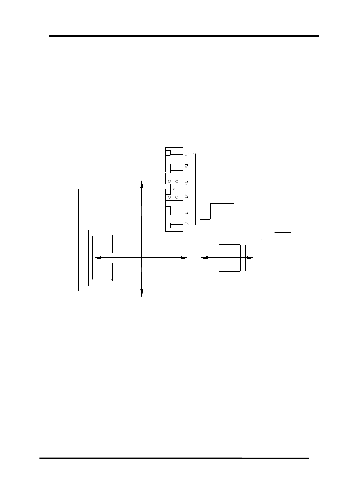
X-, Z- and B-axis and their respective positive and negative displacement directions are shown
on the above schematic diagram.
As you can see, when workpiece zero reference point is located on workpiece end (most
common case), the positive direction is outside the workpiece, while the negative direction is
on the workpiece area to be machined (inside the workpiece).
Commonly, you will operate in the quadrant defined by X+ and Z-.
The machine will enter only in X- area for facing operations.
You may also operate X+ Z+ quadrant when the workpiece is clamped on the subhead.
Page 24
C+
C-
PROGRAMMING MANUAL -24-
1.1.2 C-axis
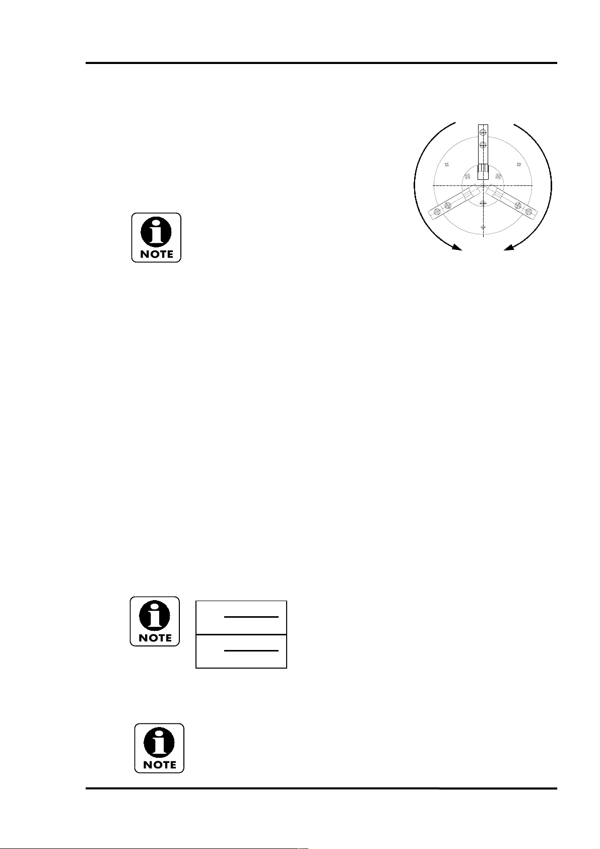
C-axis would be used to swivel the head in order to
position the workpiece for drilling operations using a
powered tool.
C+ is in clockwise direction and C- is counterclockwise
direction.
If the machine is provided with a
subhead, C1 would be for the main head
and C2 for the subhead.
1.1.3 Other axes that could be encountered when programming the machine are
A: powered tool rotating axis.
B: displacement axis used to approach the subhead to main head or move it away.
F: feed axis (related to slides) to be programmed when in operation.
In millimetres x per revolution when the head is rotating (turning)
For example:
G99 F0.3 this means “03 millimetres per revolution”.
In millimetres per minute when the head is stopped (MC).
For example:
G98 F80 this means “80 millimetres per minute”
T: is turret rotation.
R: is radius programming.
S: are head revolutions (cutting speed) This letter is always related to heads.
G50 S1000 Rpm limit.
G97 S1000 fixed rpm (for tapping and drilling).
G96 S200 cutting speed (m/min) for all turning operations.
Cutting speed formula:
Dn
Vc=
1000
Vc1000
n=
D
Vc= Cutting speed
D= Part standard diameter
n= Rpm limit.
,C: bevel programming.
,A: angle programming.
As you can see, two variants are available “,C” and “,A” with a leading comma
to differentiate them from C- and A-axis
Page 25

1.2 Tool offset
The correction value is the protruding length of tool end from the zero reference of turret disc.
The required correction values must be entered each time tool position is changed with respect
to the aforementioned position; if tool position is not changed, entering a correction value will
not be necessary as these values are stored in the memory.
New correction values must be entered when the tool is moved because of a hit
1.2.1 Entering correction values
There are two ways for entering tool correction values.
1st.) supplied with presetter.
For machines with presetter, place the presetter in position and preset the tool.
PROGRAMMING MANUAL -25-
Refer to operation manual for further information on this subject, chapter B,
2nd.) supplied without presetter.
For machines without presetter, turn the workpiece and retract the tool without moving it out
the axis. Then measure the workpiece and enter the readings in the geometry table.
To enter a value, go to the geometry table (correction value), enter the required value and
press the intermediate key; by this way the control unit will calculate the correction value.
point 4: OPERATION PROCEDURE FOR MANUAL TOOL PRESETTER
INTEGRATED IN THE MACHINE
When a tool is placed on the subhead (the case may be in which double
toolholders are used for the head and the subhead) keep in mind that correction
values are ? 21, that is, for position 1 the correction value will be 21, for position
2, 22, and so on.
1.3 Workpiece zero reference point
Workpiece zero is the workpiece protruding length from main chuck face.
It can be also placed in other location, even though it is advised not to do it, as
following up and verifying the program would much more difficult and you should
continuously calculate the difference between this position and workpiece end.
We advise you to enter workpiece zero at the beginning of the program.
Page 26
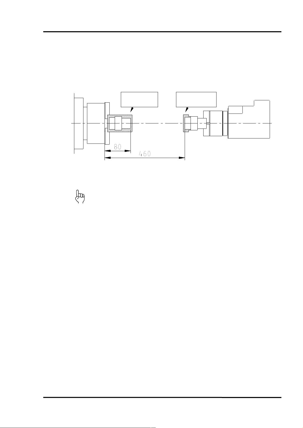
PROGRAMMING MANUAL -26-
<Standard for machines with sub-head>
In the following example we explain how a value of 80 is entered for the first stage (machining
the workpiece on the head), while a value of 460 is entered for the second stage (machining
the workpiece on the subhead).
Zero 1st phase
G10 P0 Z-80
Zero 2nd phase
G10 P0 Z-460
How preparing the machine for machining operations with transfer:
1st Determine workpiece zero and carry out the 1st machining stage.
2nd Stop the machine and verify the dimension before doing the transfer.
3nd Do the transfer and place the subhead in working position.
4nd Stop the machine and determine workpiece zero before performing the 2
machining stage.
nd
Page 27
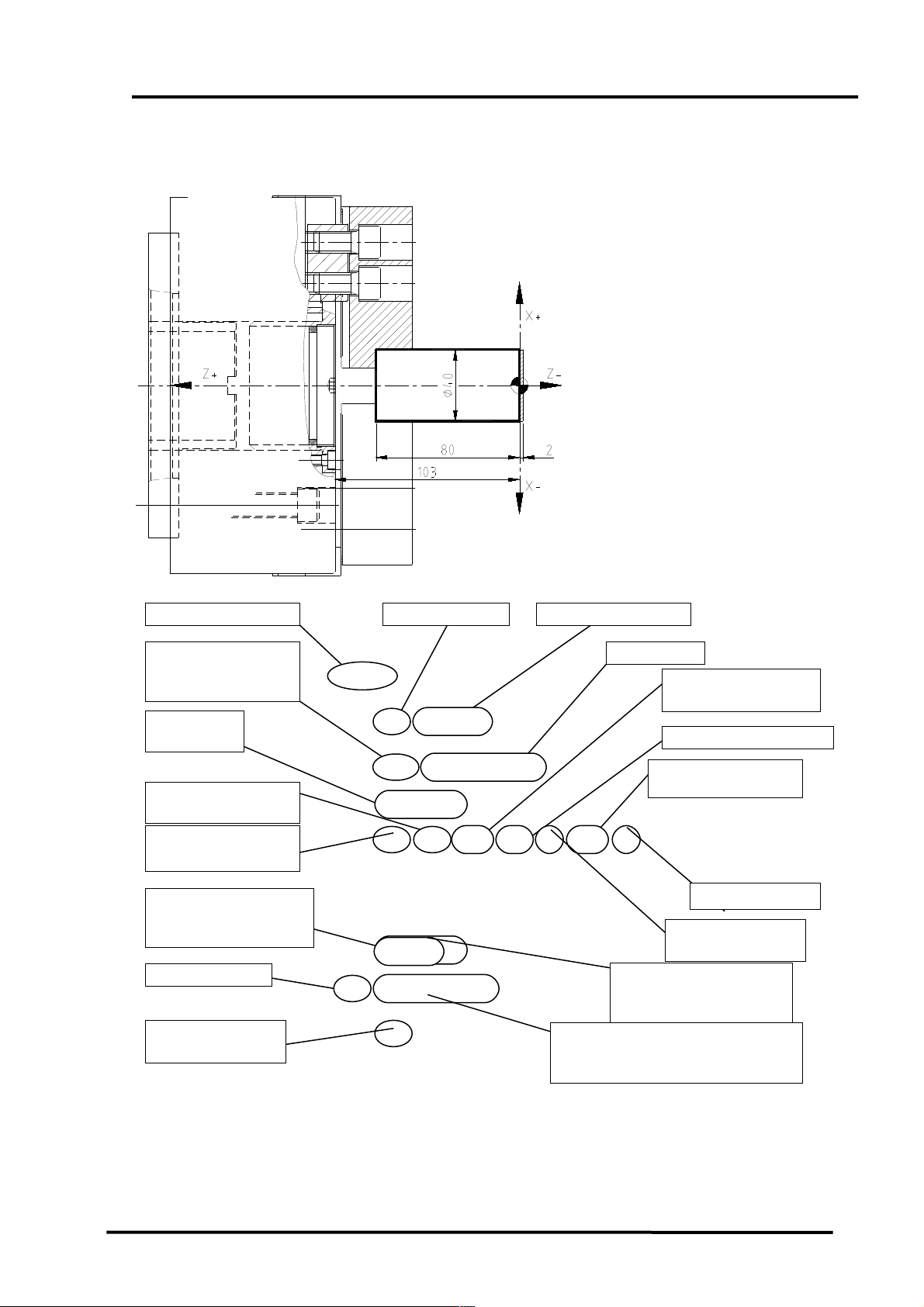
1.4 Facing
BBD 210
PROGRAMMING MANUAL -27-
O0001;
N10 G10 P0 Z-103;
N20 T101 (FACING);
N30 G50 S2000 (LIMIT R.P.M.);
N40 G96 G99 S200 F.25 M4 M200 M8
(CUTTING CONDITIONS, CHIP
CONVEYOR AND COOLANT
ACTIVATION);
N50 G0 X45 Z0 (APROXIMATION)
N60 G1 X-2;
N70 G0 X150 Z150;
N80 M30;
Program number Data input
Position the turret on
tool 1 with correction
value 01
Limit to
2000 r.p.m.
O0001;
N10 G10 P0 Z-103;
N20 T101 (STARTING WITH FACING);
Entering the feed per
N30 G50 S2000 (LIMIT R.P.M.);
revolution
Entering head speed
N40 G96 G99 S200 F.25 M4 M200 M8 CUTTING CONDITIONS,
in m/min
CHIP CONVEYOR AND COOLANT ON;
Positioning the tool on
X45 Z0, that is, 5 mm
above the workpiece
N50 G0 X45 Z0 (APPROACH);
N60 G1 X-2;
Line number
N70 G0 X150 Z150;
End and rewinding
of program
N80 M30;
Workpiece zero -103
Comment
Cutting speed
(Vc=200 m/min)
Feed (mm/revolution)
Chip conveyor
running
Coolant supply on
Head rotation in
clockwise direction
Facing up to X-2, that is,
crossing 2 mm below
the axis
Retraction at quick speed to X150
Z150, that is, at 150 mm on both
axes.
Page 28

PROGRAMMING MANUAL -28-
In this manual we will always refer to codes G type A. Refer to Fanuc
programming manual for further information on G codes.
Comment:
These are notes included in the program.
These notes are totally optional, and it is up to the programmer to enter them or
not.
These notes will be always placed in brackets () in order to prevent the program
reading them.
T101
Here is shown that the tool to be used is in position 1 and a correction value of
01 is applied.
T0101 could be also entered, as the four mandatory characters are present,
however, the first zero is optional.
Head rotation direction:
M3 head rotation direction
M4 head rotation direction reverse or clockwise.
M4 M200 M8
As seen in this example, up to 3 M codes can be programmed on each line.
It is always advisable to switch chip conveyor and coolant on at the start of the
program, excepting for special cases.
G0 X150 Z150
Note that tool retraction in this example is to 150 mm on X+ and 150 mm on Z+
from workpiece zero, and not from chuck face, as no order for changing the
position is given to workpiece zero, which in this example is maintained in the
previous position.
Line number (N10, N20...)
Line numbers are optional, and can be either entered or not.
It is advisable to enter line numbers with a margin, such as 10, 20 …, as you
can then enter intermediate operations without requiring changing all line
numbers (10, 12, 13, 20...).
G96 G99 S200 F.25
As you can see, G codes are first placed and then S and F codes. Codes can be
also entered in the following manner: G96 S200 G99 F.25
Entering codes such as G96 and G50 in the same line is not permitted.
Page 29
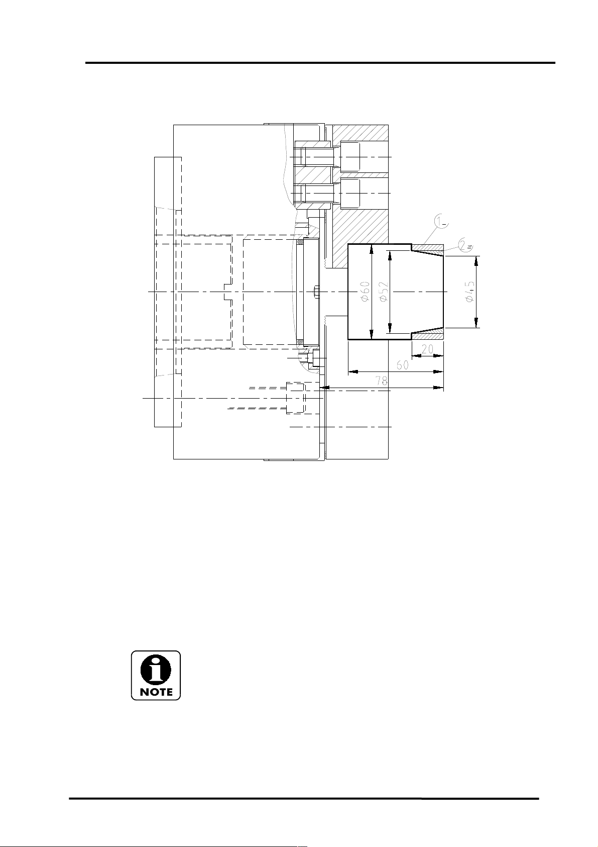
1.5 Taper turning
PROGRAMMING MANUAL -29-
BBD 210
Pass
Pass
O0002; Name of the program
N10 G10 P0 Z-78; Part-zero at –78
N20 T101; Tool chosing (pos. 01 and offset 01)
N30 G50 S1500; Spindle turning limit: 1500 rpm
N40 G96 G99 S200 F.25 M4 M8 M200; Cutting speed (m/min), Feedrate (mm/rev),
clockwise sense, Coolant, Chip conveyor
N50 G0 X52.5 Z2; Fast feedrate to point X52.5 Z2
N60 G1 Z-19.9; Machine and go to Z-19.9 (First pass)
N70 G0 X55 Z2; Fast feedrate to X55 Z2
N80 X45; Fast feedrate until the beginning of cone in X45 Z2
N90 G1 Z0; Machining feedrate to X45 Z0
N100 X52 Z-20 F.2; Machine the cone to X52 Z-20 (Second pass)
N110 X61; Machine to X61 Z-20
N120 G0 X200 Z200; Fast backwards to 200mm in both axes
N130 M30; End of programm and back to he beginning
In this example you can see that the first pass (N10 to N50) is carried out letting
part of the machining operation for de second pass (N60 to N120).
You can also see that for taper turning entering the start point and the end point
will not be necessary, and the angle between these two points will be machined.
Page 30
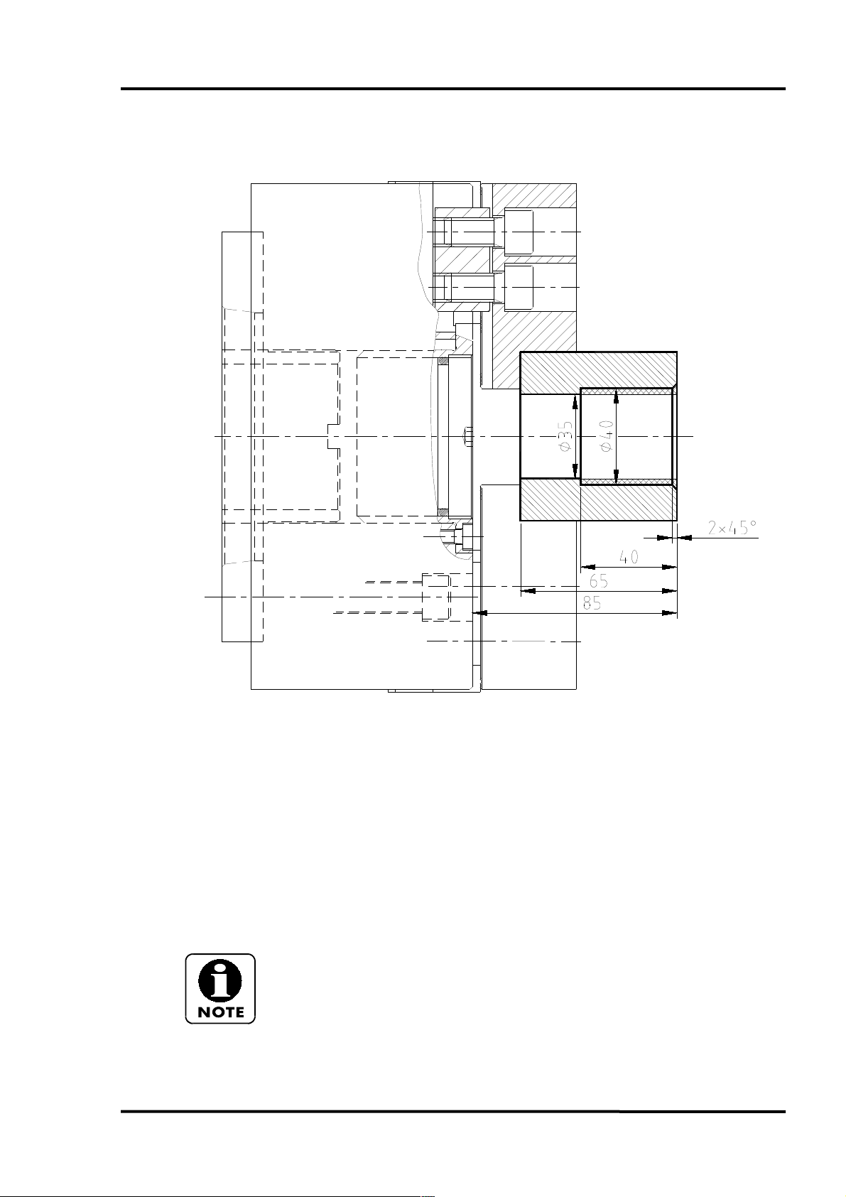
PROGRAMMING MANUAL -30-
1.6 Inside turning:
BBD 210
O0003;
N10 G10 P0 Z-85; Part zero at -85
N20 T606; Tool 06 offset 06
N30 G50 S2000; Turning speed limit: 2000 r.p.m.
N40 G96 G99 S180 F.2 M4 M8 M200; Cutting speed =180 mm/rev, feedrate 0.2 mm/rev,
clockwise sense
N50 G0 X44 Z2; Move Z2 axis to the height of the beve 2x45º
N60 G1 Z0; Move forwards machining to Z0
N70 X40 Z-2 F.15; Machine the bevel with feedrate 0.15 mm/rev
N80 Z-40 F.2; Machine the inside at ø40 with federate 0.2 mm/rev
N90 X35; Face the inside until ø35
N100 G0 Z5; Fast feedrate to Z5
N110 X200 Z100; Move backwards to X200 Z100
N120 M30; End and back to de beginning
In this example the part would have a ø35 hole.
Page 31
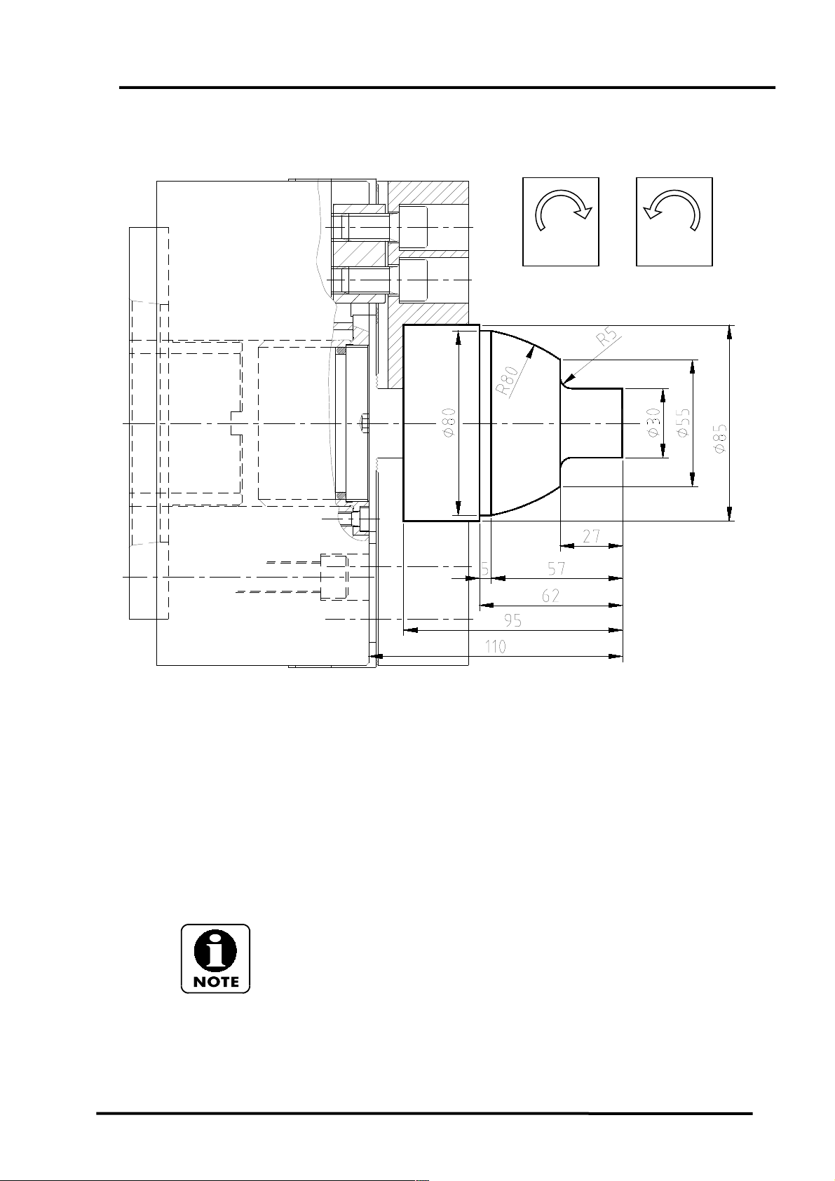
1.7 Radii
PROGRAMMING MANUAL -31-
BBD 210
G2 G3
O0004;
N10 G10 P0 Z-110;
N20 T303;
N30 G50 S2500;
N40 G96 S220 G99 F.2 M4 M8 M200;
N50 G0 X30 Z2;
N60 G1 Z-22; Machine to ø30 and Z-22
N70 G2 X40 Z-27 R5 (CLOCKWISE SENSE); Radio 5 clockwise to X40 Z-27
N80 G1 X55; Face to X55
N90 G3 X80 Z-57 R80 (COUNTERCLOCKWISE); Radio 80 counterclockwise to X80 Z-57
N100 G1 Z-62; Machine to Z-60
N110 X86; Face to X86
N120 G0 X150 Z150 M30;
In this example we consider that the part is rough machined.
As seen in this example, G2 is used to machine radii in clockwise direction and
G3 in counterclockwise direction.
You can also see that G2 or G3 is first entered, then the end point, and finally
the radius,
Page 32
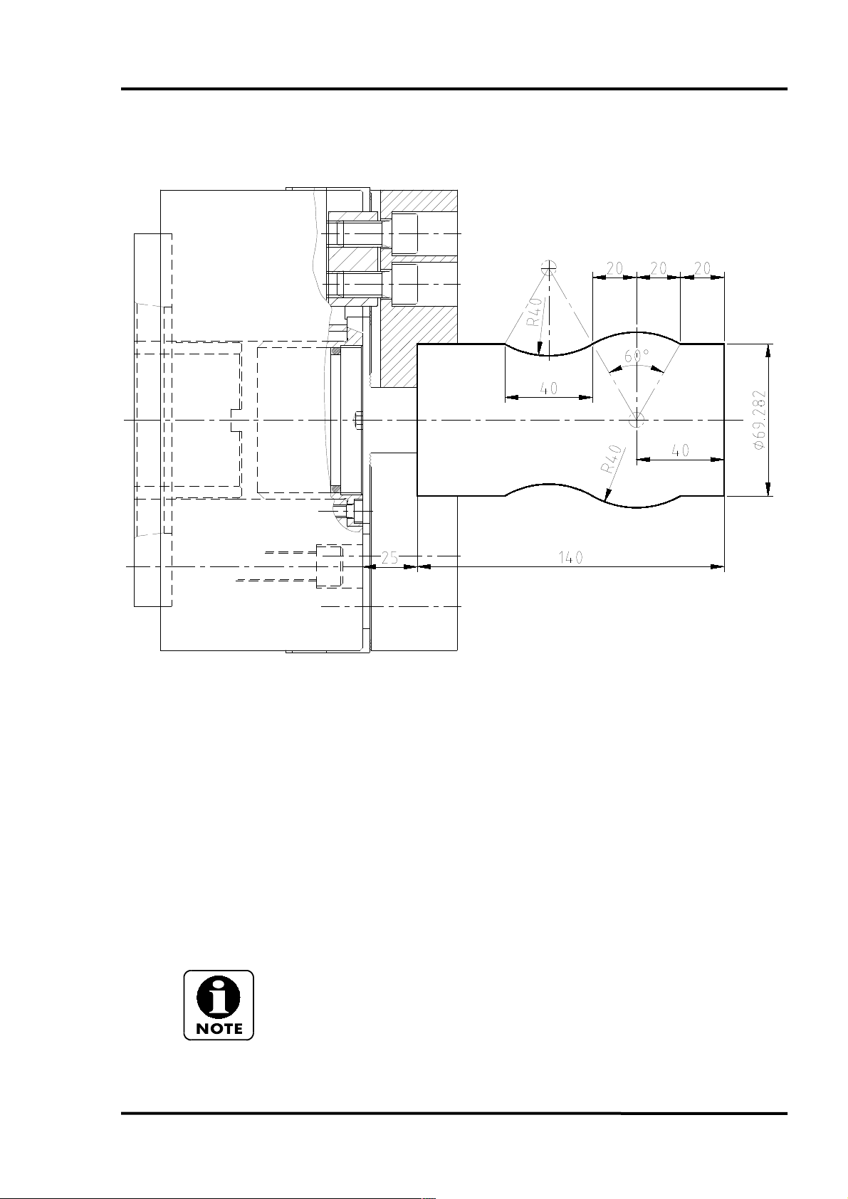
PROGRAMMING MANUAL -32-
1.8 Cylindrical interpolation
BBD 210
O0005;
N10 G10 P0 Z-165;
N20 T404;
N30 G50 S2000;
N40 G96 S200 G99 F.2 M4 M8 M200;
N50 G0 X69.282 Z2; Fast feedrate to X69.292 Z2
N60 G1 Z-20; Machining to Z-20
N70 G3 X69.282 Z-60 R40; Machine at radio 40 until point X69.282
Z-60 counterclockwise sense
N80 G2 X69.282 Z-100 R40; Machine at radio 40 until point X69.282
Z-100 clockwise
N90 G1 Z-105; Machining to Z-105
N100 G0 X150;
N110 Z10
N120 M30;
As you can see, for the interpolation, you must know the point from which this
interpolation will take place in order to change radius direction (in this example
on point X69.282 Z-60).
Page 33
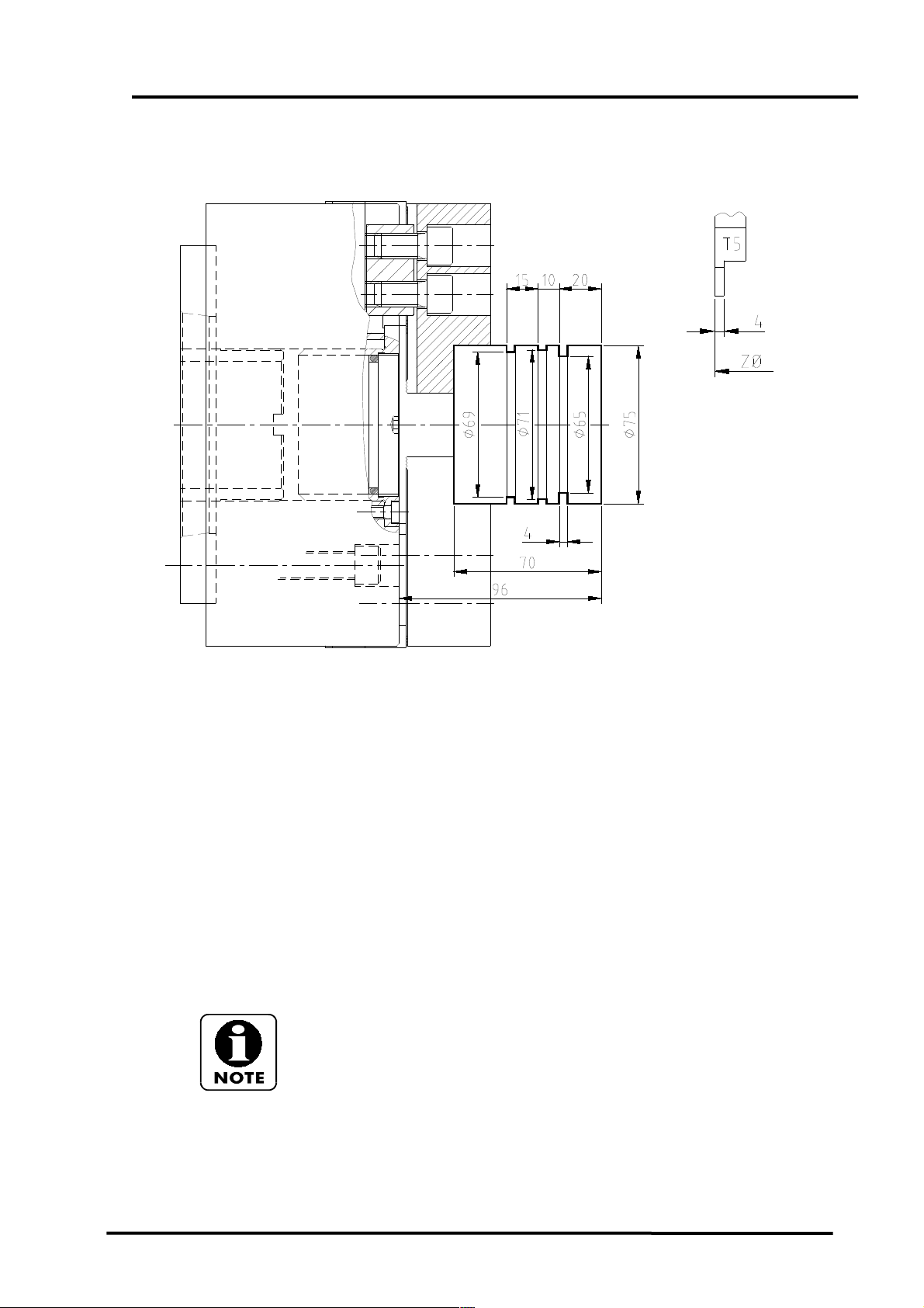
PROGRAMMING MANUAL -33-
1.9 Incremental commands (U, W, H) only for FANUC
BBD 210
O0006;
N10 G10 P0 Z-96:
N20 T505;
N30 G96 G99 S120 F.1 M4 M8 M200;
N40 G0 X78 Z-20; Fast feedrate to X78 Z-20
N50 G1 X65; Grooving to ø65
N60 G4 X1 (TEMPORIZACION 1 SEGUNDO); Timming (stop tool 1 sec X1=P1000)
N70 G0 X78; Fast feedrate to X78
N80 W-10 (INCREMENTAL); Increment –10 en el eje Z (W=Z)
N90 G1 U-7; Increment –7 en el eje X (U=X)
N100 G4 X1; Timming
N110 G0 U7; Fast feedrate 7 in axis X (U=X)
N120 W-15; Increment –15 en eje Z (W=Z)
N130 G1 U-9; Groove until –9 in axis X (ø69)
N140 G4 X1; Timming
N150 G0 U9; Fast feedrate 9 in axis X (ø78)
N160 X200 Z200;
N170 M30;
In this example, slots of de ø65, ø71 and ø69 are to be machined. For this, tool
T5 will be used.
The references are: U for X-axis (U-command also on ø to)
W for the Y-axis
H for the C-axis
Time delays are entered each time a slot is machined in order to stop the tool
for a given time and then properly complete the machining operation.
Page 34
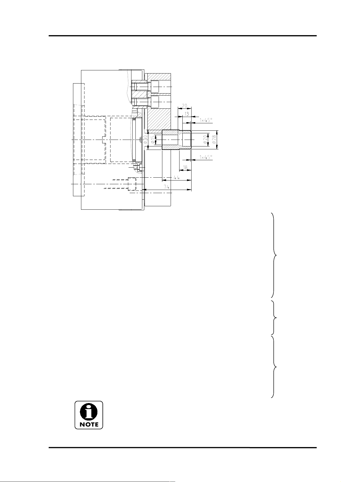
PROGRAMMING MANUAL -34-
1.10 Example for operation
BBD 210
Tools:
T1= Outside and facing.
T2= ø15 twist drill.
T3= Inside.
O0007;
N10 G10 P0 Z-74;
N20 T101 (EXTERNAL); Tool 1
N30 G50 S2500;
N40 G96 S220 G99 F.25 M4 M8 M200; Clockwise turning
N50 G0 X35 Z0;
N60 G1 X-2;
N70 G0 X26 Z2;
N80 G1 Z0;
N90 X28 Z-1 F.2;
N100 Z-18 F.25;
N110 X32;
N120 G0 X150 Z200 M5; Remove axes and stop spindle
N130 T202 (BROCA DE 15); Tool 2
N140 G97 S600 G99 F.15 M3; Fixed turn. speeds, Count.clockwise
N150 G0 X0 Z3;
N160 G1 Z-47;
N170 G0 Z100 M5; Remove axes and spindle stop
N180 T303 (INTERIOR); Tool 3
N190 G96 S150 G99 F.25 M4; Clockwise turning
N200 G0 X22 Z3;
N210 G1 Z0;
N220 X20 Z-1 F.15;
N230 Z-13 F.2;
N240 X15 Z-20 F.15;
N250 G0 Z5;
N260 X200 Z150 M30;
External machiningBoringInside machining
To go from M3 to M4, first enter M5 to stop the head.
Page 35
2. G FUNCTIONS
G functions used in machining programs are described in this section.
This section describes G codes more commonly used. Refer to CNC unit
manual supplied by the manufacturer for G codes not included in this section.
2.1 List of G codes
Also called preparatory functions, G codes consist of a G address followed by a numerical
value which defines a machining mode or an axis displacement within a program block. The
CNC unit will control the specified G code.
G codes are classified into two types:
Type Description
PROGRAMMING MANUAL -35-
Non-modal G code
(Group 00, excepting G10 and G11)
Modal G code
(Groups other than 00)
For instance, G00 and G01 are modal G codes, as they pertain to a group other than 00.
G01 X_Z_;
X_; G01 is valid within this range
Z_;
G00 X_Z_;
1- More than one G code may be programmed in a block, provided they are
from different groups.
2.- If more than one G code in a group is programmed in a block, only the last
programmed G code will be executed.
3.- If a G code not specified in the list of G codes or a G code related to a
function not available in the machine is programmed, alarm message no. 010
will be displayed.
The G code is valid within the block in which it was
programmed
The G code will remain valid until another G code of
the same group is programmed.
4.- G codes marked with % are activated by default when CNC is started or
RESET key pressed.
Page 36
PROGRAMMING MANUAL -36-
2.1.1 TL, TB, TBI models
*1: Standard machines with automatic tailstock (T).
*2: Standard for machines with powered tool
*3: Optional for machines with sub-head (S).
*4: Standard for machines with sub-head (S).
*5: Optional for machines with powered tool.
) = Standard, + = Optional, x = Not available
%
%
%
%
G Code
Group Function
A B C
G00 G00 G00
G01 G01 G01 Linear interpolation (machining feed)
G02 G02 G02
G03 G03 G03
G04 G04 G04 00 Time delay
G07.1
(G107)
G10 G10 G10 Programmable data input
G11 G11 G11 Programmable data input disabled
G12.1
(G112)
G13.1
(G113)
G17 G17 G17
G18 G18 G18 Zp-Xp plane selection
G07.1
(G107)
G12.1
(G112)
G13.1
(G113)
G07.1
(G107)
G12.1
(G112)
G13.1
(G113)
Positioning (fast feedrate)
01
Circular clockqwise or helical
interpolation (clockwise)
Circular counterclockwise or helical
interpolation (counterclockwise)
Cylindrical interpolation x
00
Interpolation mode in polar coordinates x
21
Interpolation mode in polar coordinates
disabled
Xp-Yp plane selection
16
Remarks
)
)
)
)
)
2
)
)
2
2
x
)
)
%
G19 G19 G19 Yp-Zp plane selection
G20 G20 G70
G21 G21 G71 Input in mm
G22 G22 G22
G23 G23 G23
G27 G27 G27
G28 G28 G28 Go to reference point
G30 G30 G30
G31 G31 G31 Skip function
Input in inches
06
Verify traverse limit stored in the
memory. Function enabled
09
Verify traverse limit stored in the
memory. Function disabled
Go to reference point verification
00
Go to second, third and fourth reference
point
)
+
+
+
+
)
)
+
)
Page 37

PROGRAMMING MANUAL -37-
%
%
%
G Code
Group Function
A B C
G32 G33 G33
G34 G34 G34 Variable pitch threading
G40 G40 G40
G41 G41 G41
G42 G42 G42
G50 G92 G92
G38 G38 G38 Workpiece transfer cycle x
G50.2
(G250)
G51.2
(G251)
G52 G52 G52
G53 G53 G53 Defining machine co-ordinate system
G54 G54 G54
G55 G55 G55
G56 G56 G56
G57 G57 G57
G58 G58 G58
G59 G59 G59
G65 G65 G65 00 Call macro
G50.2
(G250)
G51.2
(G251)
G50.2
(250)
G51.2
(G251)
Threading
01
Disable tool insert radius compensation
Tool insert radius leftward
07
compensation
Tool insert radius rightward
compensation
Selection of co-ordinate system or
selection of maximum spindle speed
00
Polygonal turning. Disable x
20
Polygonal turning x
Defining local co-ordinate system
00
Selection of workpiece co-ordinate
system (1 co-ordinate)
Selection of workpiece co-ordinate
system (2 co-ordinates)
Selection of workpiece co-ordinate
system (3 co-ordinates)
14
Selection of workpiece co-ordinate
system (4 co-ordinates)
Selection of workpiece co-ordinate
system (5 co-ordinates)
Selection of workpiece coordinate
system (6 co-ordinates)
Remarks
)
)
)
)
)
)
4
5
5
+
+
+
+
+
+
+
+
+
%
%
G66 G66 G66
G67 G67 G67 Call macro on modal mode. Disable
G70 G70 G72
G71 G71 G73 Stock removal on turning
G72 G72 G74 Stock removal on facing
G73 G73 G75 Lead repetition
G74 G74 G76 Deep drilling on end face
G75 G75 G77 Drilling external/internal diameter
G76 G76 G78 Multiple threading cycle
G80 G80 G80 10 Drilling cycle. Disable
Call macro on modal mode
12
Finishing cycle
00
+
+
)
)
)
)
)
)
)
2
+
Page 38

PROGRAMMING MANUAL -38-
G Code
Group Function
A B C
G83 G83 G83 Drilling cycle on front face
G84 G84 G84 Drilling and tapping cycle on front face
G86 G86 G86 Boring cycle on front face
G87 G87 G87 Drilling cycle on a side
G88 G88 G88 Drilling and tapping cycle on a side
G89 G89 G89 Boring cycle on a side
G90 G77 G20
G92 G78 G21 Threading cycle
G94 G79 G24 Turning cycle on end face
G96 G96 G96
%
G97 G97 G97 Constant cutting rate control. Disable
G98 G94 G94
%
G99 G95 G95 Advance per revolution
- G90 G90
- G91 G91 Incremental programming
- G98 G98
- G99 G99
G138 G138 G138
G238 G238 G238
G380 G380 G380 Rigid threading cycle. Disable x
G384 G384 G384 Rigid threading cycle X
Machining cycle on inside/outside
diameter
01
Constant cutting rate control
02
Advance per minute
05
Absolute programming
03
Return to initial level (refer to
Explanation 6)
11
Return to R point level (refer to
Explanation 6)
Workpiece clamping cycle with
automatic tailstock (I)
Workpiece clamping cycle with
automatic tailstock (II)
00
Remarks
2
+
2
+
2
+
2
+
2
+
2
+
+
+
+
)
)
)
)
)
)
)
)
1
x
1
x
2
2
Page 39

3. M FUNCTIONS
M functions used in machining programs are described in this section.
For M codes not included in this manual, refer to CMZ. In some machine
models, other M codes for functions different to those described herein may be
availbale.
3.1 List of M codes
These codes control functions complementary to those controlled by G codes. For instance,
coolant supply, head rotation direction, etc.
CMZ Function Description
M000 Program stop
M001 Optional stop
M002 Program end End of program and CNC reset
M003 Spindle 1 start (normal) Spindle 1 running in CW direction
M004 Spindle 1 start (reverse) Spindle 1 running in CCW direction
M005
M006 Turret head rotation (normal) Turret rotates in CW direction
M007 Turret head rotation (reverse) Turret rotates in CW direction
M008 Coolant ON Coolant 1 supply ON (Coolant 1 start key)
M009 Coolant OFF All coolnat supplies stopped (1 and 2)
M010 Chuck clamp (spindle 1)
M011 Chuck unclamp (spindle 1)
M012 Chucking pressure 1 (spindle 1) Reduced pressure on spindle 1 activated
M013 Chucking pressure 2 (spindle 1) Reduced pressure on spindle 1 activated
M015 In-position check valid
M016 In-position check invalid
M018 Auxiliary coolant ON Auxiliary coolant supply ON
M019 Spindle orientation (spindle 1) Spindle 1 is oriented (without C-axis)
M020 Steady rest 1 close Steadyrest is closed
M021 Steady rest 1 open Steadyrest is opened
M023 Chamfering ON
M024 Chamfering OFF M23 disabled
M025 Tailstock spindle out Tailstock quill is moved out
M026 Tailstock spindle in Tailstock quill is moved in
M027 Tailstock body unclamp Automatic tailstock base is unlocked
M028 Tailstock body clamp Automatic tailstock base is locked
M029 Rigid tapping in spindle ON (spindle 1)
M030 Program end and rewind End of program, rewinding and CNC reset
CMZ Function Description
M033 Phase synchronous operation OFF Speed synchronised on both heads
Spindle 1/spindle 2/rotary tool spindle
stop
PROGRAMMING MANUAL -39-
All machine functions are unconditonally
stopped
Machine functions are conditinally stopepd
(OPS function activated)
Spindle 1, spindle 2 and powered tool are
stopped
Workpiece clamped by chuck/collet on spindle
1
Workpiece released from chuck/collet on
spindle 1
Tool lead-out at 45º (Thread end without
bleeding) refer to p5130
Page 40

PROGRAMMING MANUAL -40-
M034 Phase synchronous operation ON
M035 Work counter/total counter Part counter
M036 Syncrhonization OFF Synchronisation deactivated
M040 Cut-off detection
M041 Workpiece pushing check ON B-axis limit activated
M042 Workpiece pushing check OFF B-axis limit deactivated
M045
M047 Workpiece ejector OUT Workpiece ejector on spindle 2
M048 Override cancel OFF Feed override is set to 100%
M049 Override cancel ON Feed override selector switch is released
M050 Spindle brake clamp (spindle 1) Spindle 1 and spindle 2 braking is activated
M051
M052 Spindle low pressure brake clamp
M053
M054 Chuck air blow ON (spindle 1) Jaws on spindle 1 are blown with air
M055
M059 Chuck air blow OFF (spindle 1) Blowing of jaws on spindle 1 is deactivated
M060
M061
M062 Operation of bar feeder
M063 Movement detection
M065 Order for bar change
M066 Activate monitoring
M067 Deactivate monitoring
M070 Automatic door open Automatic door is opened
M071 Automatic door close Automatic door is closed
M072
Disable steadyrest opening when the
spindle is turning
Spindle brake unclamp (spindle 1,
spindle 2)
Contact sensor airo blow ON (spindle
1)
Air blow sensor OFF for automatic
toolsetter on machine (spindle 1)
Activate spindle and tool sincronization
mode
Deactivate spindle and tool
sincronization mode
Automatic toolsetter arm in machine
UP
Jaws and speed synchronised on the two
heads
Cutting off detection (workpiece on spindle 1)
for transfer to spindle 2
Spindle 1 and spindle 2 braking is deactivated
M073 Parts catcher OUT Part collector is moved out (to collect a part)
M074 Parts catcher IN Part collector is moved in (to remove a part)
M075 X-axis mirror image OFF X-mirror function is activated
M076 X-axis mirror image ON X-mirror function is deactivated
M080 C-axis joint (spindle 1) C-axis mode is activated in spindle 1
M081 C-axis release (spindle 1, spindle 2) C-axis mode is deactivated in both spindles
M083 Rotary tool spindle start (normal) Powered tool runs in CW direction
M084 Rotary tool spindle start (reverse) Powered tool runs in CCW direction
M085 Stop rotary tool Powered tool is stopped
M087 Piece meassurement ON (spindle 1)
M088 Piece meassurement OFF (spindle 1)
CMZ Function Description
M090 Spindle indexation at 45º
M091 Spindle indexation at 90º
M092 Spindle indexation at 180º
Page 41

PROGRAMMING MANUAL -41-
M096
M098 Sub-program call A sub-program is called
M099
M125 The part is clamped with T tailstock The tailstock is moved in G1 against the part
M126 The part is unclamped with T tailstock
M200 Chip conveyor forwards
M201 Stop chip conveyor
M203 Spindle 2 start (normal) Spindle 2 runs in CW direction
M204 Spindle 2 start (reverse) Spindle 2 runs in CCW direction
M205 Stop of spindle 2
M210 Chuck clamp (spindle 2) Workpiece clamped on chuch/collet 2
M211 Chuck unclamp (spindle 2) Workpiece released from chuck/collet 2
M212 Chucking pressure 1 (spindle 2) Pressure reduction on spindle 2 is activated
M213 Chucking pressure 2 (spindle 2) Pressure reduction os spindle 2 is deactivated
M219 Spindle orientation (spindle 2) Spindle 2 is oriented (without C-axis)
M222 Check spindle 2 emty chucks
M250 Clamp spindle 2 brake Spindle 1 and spindle braking is activated
M251 Clamp spindle 2 brake pressure
M252 Clamp spindle 2 low pressure
M253
M254 Chuck air blow ON (spindle) Jaws on head 2 are blown with air
M255
M257 Air blow OFF (spindle 2)
M258 Air blow sensor OFF (subspindle)
M259 Chuck air blow OFF (spindle) Blowing of jaws on head 2 is deactivated
M260
M261
M280 C-axis joint (spindle 2) C-axis mode is activated in spindle 2
M281 Deactivate C axis (spindle 2)
Open chucks enabled when spindle is
turning
Sub-program end Repetition of
program
Contact air blow sensor ON
(subspindle)
Air blow sensor OFF for automatic
toolsetter in machine (subspindle)
Activate subspindle and driven tool
syncronization
Deactivate subspindle and driven tool
syncronization
Open jaws enabled with head running
Return to either main program or program start
The tailstock is moved away in G1 from the
part
M287 Meassurement of piece ON (spindle 2)
M288
M301
M302
M303 Signal to select spindle 1
M304 Signal to select spindle 2
M306 Tool control from part program (A axis)
CMZ Function Description
M307
M310
Meassurement of piece OFF (spindle
2)
Direct turning sense of spindle in rigid
tapping (spindle 1 or 2)
Reverse turning sense of spindle in
rigid tapping (spindle 1 or 2)
Tool control from PMC (axis control
PMC)
Automatic selection of spindle coil in
main spindle
Page 42

PROGRAMMING MANUAL -42-
M311
M312
M316 Unlock turret
M318
M319 Turn back to tool zero
M320
M321
M322
M337 Piston keeper up
M338 Piston beeper down
M382 Washing coolant ON
M383 Washing coolant OFF
M384 Spindle 1 orientation and roof opening
M387 Spindle 2 orientation and roof opening
M408 Special M code output
M409
M410
M411
M412
M413
M414
M415
M416
M417
M418
M419
M420
M421
M422
M423
M424 Special M code output
M425
M426
M427
M428
M429
M430
M431
M432 Part catcher cycle
CMZ Function Description
M434 Pressure 1 in tailstock – high
M435 Pressure 2 in tailstock – low
M438 Graphic mode axis C
M440 Special M code output Client M function
M441
M442
Selection of LOW coil (star) in main
spindle
Selection of HIGH coil (delta) in main
spindle
Unable turret turning during axis
movement
Automatic selection of spindle coil in
subspindle
Selection of LOW coil (star) in
subspindle
Selection of HIGH coil (delta) in
subspindle
Special M code output
Special M code output
Special M code output
Special M code output
Special M code output
Special M code output
Special M code output
Special M code output
Special M code output
Special M code output
Special M code output
Special M code output
Special M code output
Special M code output
Special M code output
Special M code output
Special M code output
Special M code output
Special M code output
Special M code output
Special M code output
Special M code output
Special M code output
Special M code output
Part catcher cycle (removes part from spindle 2
during another part is machined in spindle 1)
Client M function
Client M function
Page 43

PROGRAMMING MANUAL -43-
M443
M444
M445
M446
M447
M448
M449
M454
M455
M456
M457
M458
M459
M470
M471
M472
M473
M474
M478
M479
Special M code output
Special M code output
Special M code output
Special M code output
Special M code output
Special M code output
Special M code output
Bar unloader forwards movement
signal
Bar unloader backwards movement
signal
Tailstock air blow ON
Tailstock air blow OFF
Driven tool air blow ON
Driven tool air blow OFF
Roof opening
Roof closing
Unload cycle. Stop subspindle, move
unloader forwards, open check, blow
check, move unloader backwards
Stop of operations programmed by
M472
Call to robot cycle (robot command)
Coolant through spindle 2 ON
(Taladrina 3)
Coolant through spindle 2 OFF
(Coolant 3)
Client M function
Client M function
Client M function
Client M function
Client M function
Client M function
Client M function
Page 44
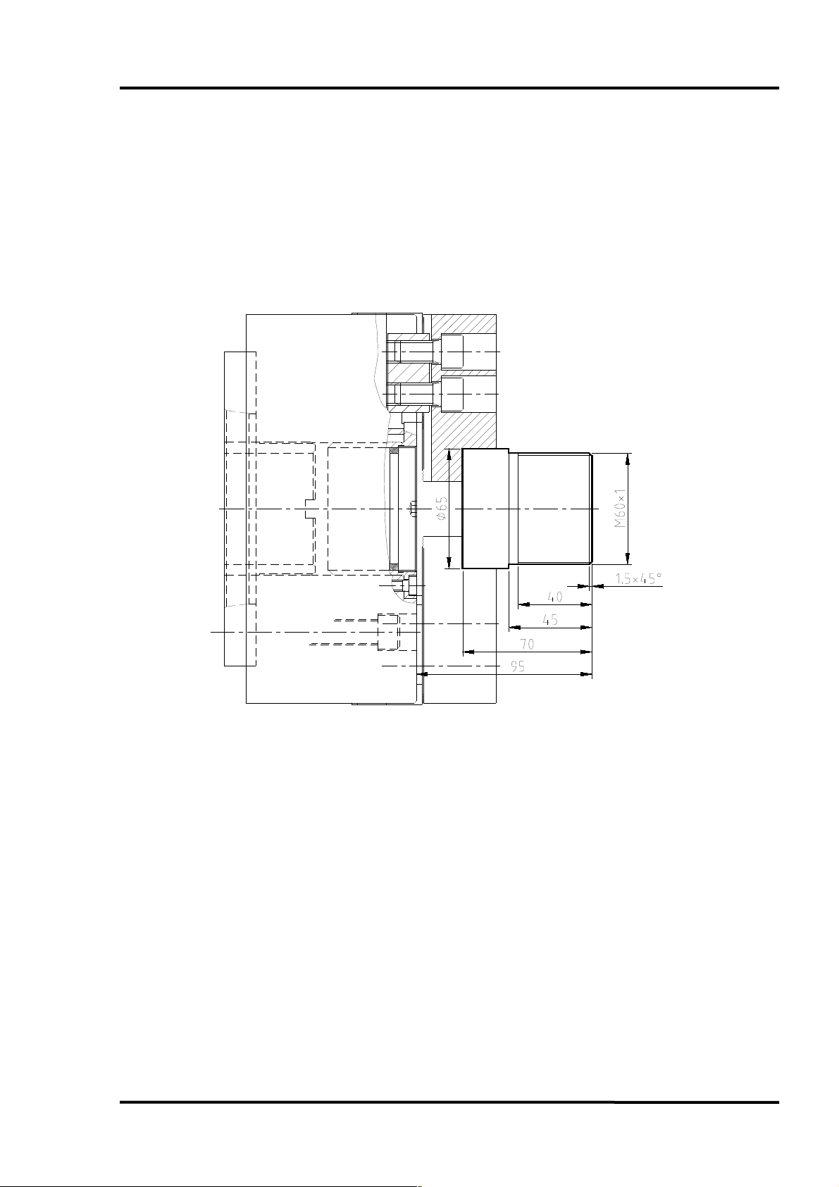
PROGRAMMING MANUAL -44-
4. THREADING
BBD 210
Page 45

PROGRAMMING MANUAL -45-
O0008;
N10 G10 P0 Z-95;
N20 T101 (Surfacing);
N30 G50 S2500;
N40 G96 S200 G99 F.25 M3 M8 M200;
N50 G0 X70 Z0;
N60 G1 X-2;
N70 G0 X57 Z1;
N80 G1 Z0;
N90 X59.9 Z-1.5;
N100 Z-45;
N110 X66;
N120 G0 X150 Z100;
N130 T202; (Threading);
N140 G97 S700 M3; Fixed revolutions, counterclockwise
N150 G0 X60 Z2 (Start 2 times the step);
N160 X59.4 (First pass); First pass to X59.4
N170 G32 Z-40 F1 (F=step); Threading to Z-40 step 1
N180 G0 X62;
N190 Z2;
N200 X58.8 (Second pass); Second pass X58.8
N210 G32 Z-40 F1; Thread until Z-40 pass 1
N220 G0 X62;
N230 Z2;
N240 X58.7 (Last pass); Last pass to X58.7
N250 G32 Z-40 F1; Threading until Z-40, pass 1
N260 G0 X62;
N270 X200 Z2
00 M30;
The outside thread area will be turned to a diameter (- 0.1 mm the metric
diameter) in order to prevent that thread tips can result in sharp edges.
G32 for threading operations, always operate at fixed rpm (G97).
When retapping threads, do not release the workpiece, do not change the
speed and do not change the start point.
Page 46
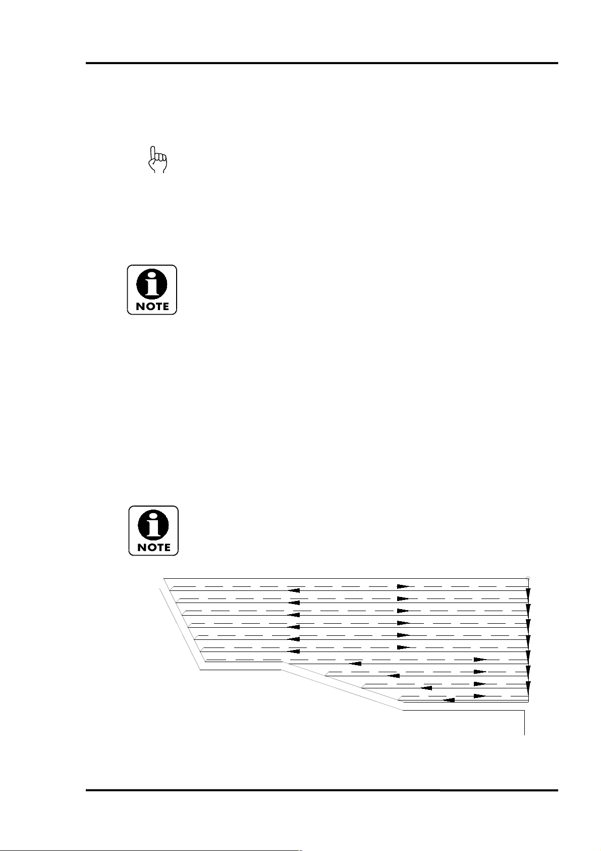
PROGRAMMING MANUAL -46-
5. CONTROL FIXED CYCLES
You can find here a brief explanation of machining cycles. For a detailed
description, refer to section 13 of FANUC manual, part 1/2
5.1 G70 Finishing cycle
G70 P1000 Q1100
P Block number from which the profile operation begins.
Q Block number from which the profile operation ends.
At the end of each cycle sequence the machine is always positioned in the
position at which this cycle sequence was started. The tool will be commonly
located in the position used for rough machining.
The profile allows changing X and Z direction.
5.2 G71 Longitudinal roughing cycle parallel to Z-axis
G71 U3 R1
G71 P100 Q200 U0.3 W0.1 F0.25
U Cut depth on radius (mm).
R Retraction in radial direction from diameter to prevent touching the machined diameter
(mm).
P Block number from which the profile operation begins.
Q Number of end block of profile.
U Finishing allowance for radius on X-axis (mm).
W Finishing allowance on Z-axis (mm).
F Instantaneous feed (mm/revolution).
At the end of each cycle sequence the machine is always positioned in the
position at which this cycle sequence was started.
The positioning allows changing X- and Z-axis direction.
If the block G71 U3 R1 is entered for the first time, it will be stored in the
parameter U=P5132 and R=P5133 and will be kept until changed in either the
program or the parameter.
Page 47
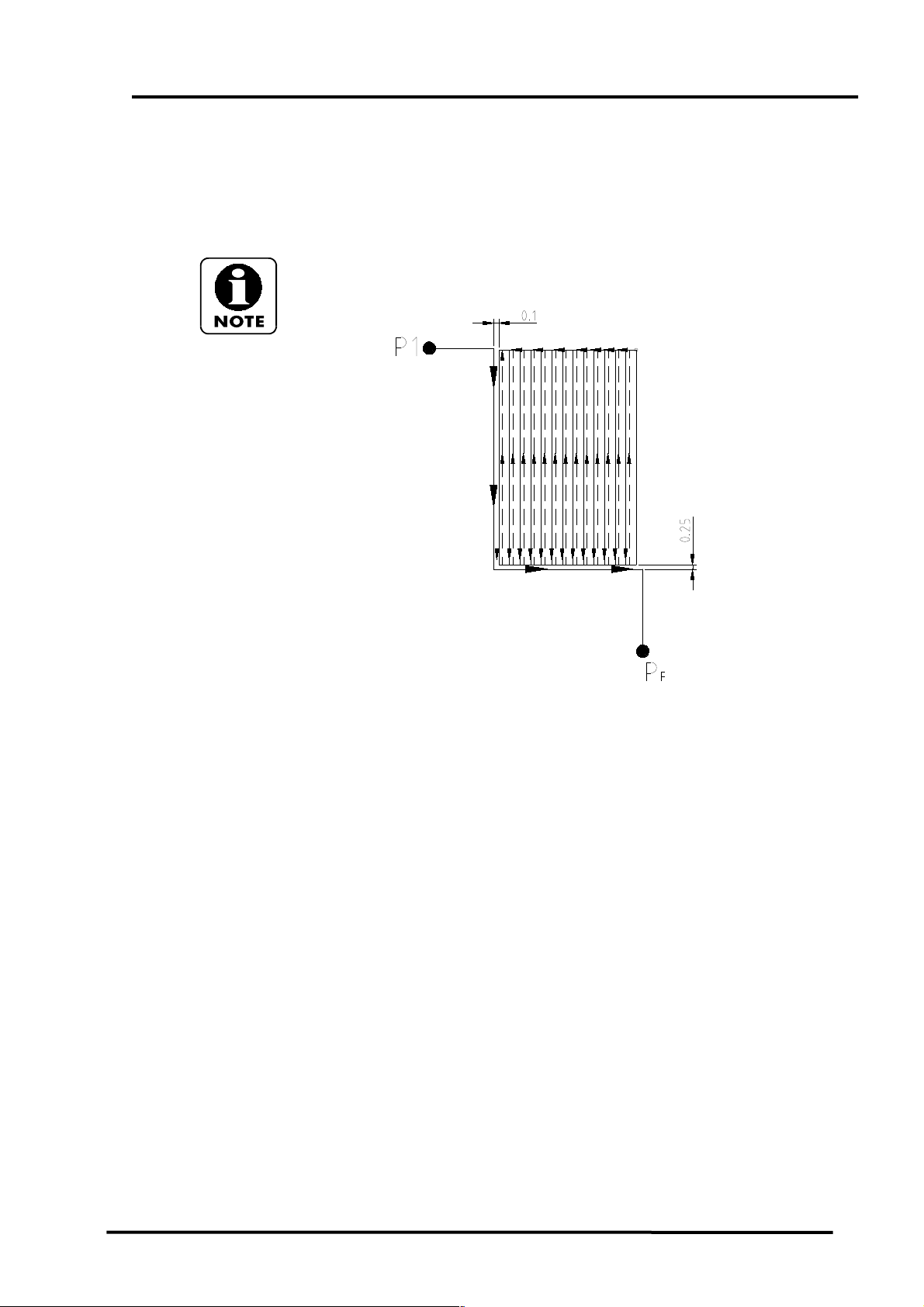
PROGRAMMING MANUAL -47-
5.3 G72 Cross roughing cycle transversal parallel to X-axis
G72 W3 R1
G72 P100 Q200 U0.25 W0.1 F0.3
Same as the above one, excepting for the profile.
5.4 G73 Roughing cycle with passes parallel to profile
G73 U9 W9 R3
G73 P100 Q150 U0.4 W0.1 F0.3
U Stock allowance (for radius) unmachined on X-axis (mm).
W Stock allowance on Z-axis (mm).
R Number of roughing passes.
P Block number from which the profile operation begins.
Q Number of end block of profile.
U Finishing allowance for radius on X-axis (mm).
W Finishing allowance on Z-axis (mm).
F Instantaneous feed (mm/revolution).
5.5 G74 Drilling cycle (chip breakage)
G74 R0.5
G74 Z-100 Q25000 F0.25
R Return distance on drilling to break chips (in mm), changes to P722.
Z Final drilling depth (absolute dimensions in mm).
Q Cut depth per pass (micron).
WARNING: On machines with specification in tenths of micron, “Q” data must be specified in
tenths of micron.
F Instantaneous feed (mm/revolution).
Page 48

PROGRAMMING MANUAL -48-
5.6 G83 Drilling cycle (chip breakage with retraction at the start)
G0 X0 Z3
G83 Z-60 Q20000 F0.2
Z Final drilling depth (absolute dimensions in mm).
Q Cut depth per pass (micron).
WARNING: On machines with specification in tenths of micron, “Q” data must be specified in
tenths of micron.
F Instantaneous feed (mm/revolution).
5.7 G74 Front counterboring cycle
G74 R0.4
G74 X50 Z-4 P3000 Q4000 F0.15
R Retraction (mm) to break chips.
X(U) End position on X-axis (mm).
Z(W) End position in slot direction (mm).
P Displacement on X-axis for next passes (micron).
WARNING: On machines with specification in tenths of micron, “P” data must be specified in
tenths of micron.
Q Cutting depth (micron).
WARNING: On machines with specification in tenths of micron, “Q” data must be specified in
tenths of micron.
F Instantaneous feed (mm/revolution).
5.8 G75 Longitudinal grooving cycle
G75 R0.2
G75 X43 W-7.5 P4000 Q25000 F0.15
R Retraction (mm) to break chips
X Groove bottom diameter (mm).
W Groove end point on Z-axis (mm) if Z is specified in absolute dimensions and W is the
displacement in incremental mode; from left-hand to right-hand (W+) and from right-hand to
left-hand (W-), always subtracting tool width.
P Cutting depth on X-axis (micron).
WARNING: On machines with specification in tenths of micron, “P” data must be specified in
tenths of micron.
Q Displacement on Z-axis for next pass (micron).
WARNING: On machines with specification in tenths of micron, “P” data must be specified in
tenths of micron.
F Instantaneous feed (mm/revolution).
IMPORTANT: Roughing cycles are without tool radius compensation. Because
of this, higher allowances will be specified for X and Z depending on tool radius.
Page 49

5.9 G76 Threading cycle
G76 P010060 Q30 R0.03
G76 X100 Z-40 R0 P1300 Q650 F2
P01 Number of finishing passes.
P00 Thread runout; distance at which thread outlet is started, in tenths of turn Example: If
thread pitch is 2 and 20 is entered: 2mm x 2 turns = 4 mm (thread runs out 4mm before the
end point).
P60 Thread angle in degrees
Q Minimum pass (micron).
WARNING: On machines with specification in tenths of micron, “Q” data must be specified in
tenths of micron.
R Finishing allowance (mm).
X Thread bottom diameter (mm).
Z Thread end point on Z-axis (absolute dimensions in mm).
R Height difference on radius (mm) for taper threads, if start point is ø20 and end point ø20,
then R-5.
P Thread height (micron).
WARNING: On machines with specification in tenths of micron, “Q” data must be specified in
tenths of micron.
Q Cut depth for first pass (micron).
WARNING: On machines with specification in tenths of micron, “Q” data must be specified in
tenths of micron.
F Thread pich (mm).
PROGRAMMING MANUAL -49-
Page 50
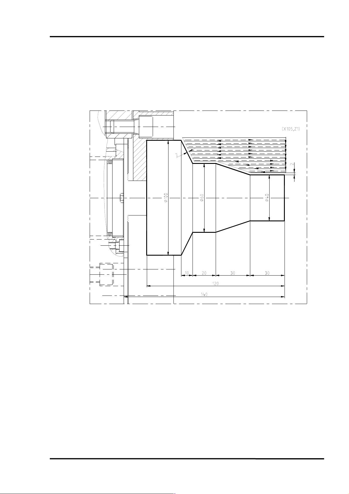
PROGRAMMING MANUAL -50-
6. EXAMPLES OF FIXED CYCLES
6.1 G71 Fixed roughing cycle
O0071;
N10 G10 P0 Z-130;
N20 T101 (ROUGHING);
N30 G50 S2500;
N40 G96 S200 G99 F.25 M3 M8 M200;
N50 G0 X105 Z0;
N60 G1 X-2 (SURFACING);
N70 G0 X105 Z1 (STARTING POINT AND END OF FIXED CYCLE);
N80 G71 U3 R1 (DEPTH OF PASS= U3mm REMOVING R1mm);
N90 G71 P100 Q140 U2 W2 F0.3 (ROUGHING LETTING OFFSETS OF 2 mm IN X AND Z);
N100 G0 X40 (FROM BLOCK 100 TO140 THE PROFILE IS DEFINED);
N110 G1 Z-30;
N120 X60 Z-60;
N130 Z-80;
N140 X100 Z-90;
N150 G70 P100 Q140 (FINISHING CYCLE)
N160 G0 X200 Z200 M5;
N170 M30;
Page 51
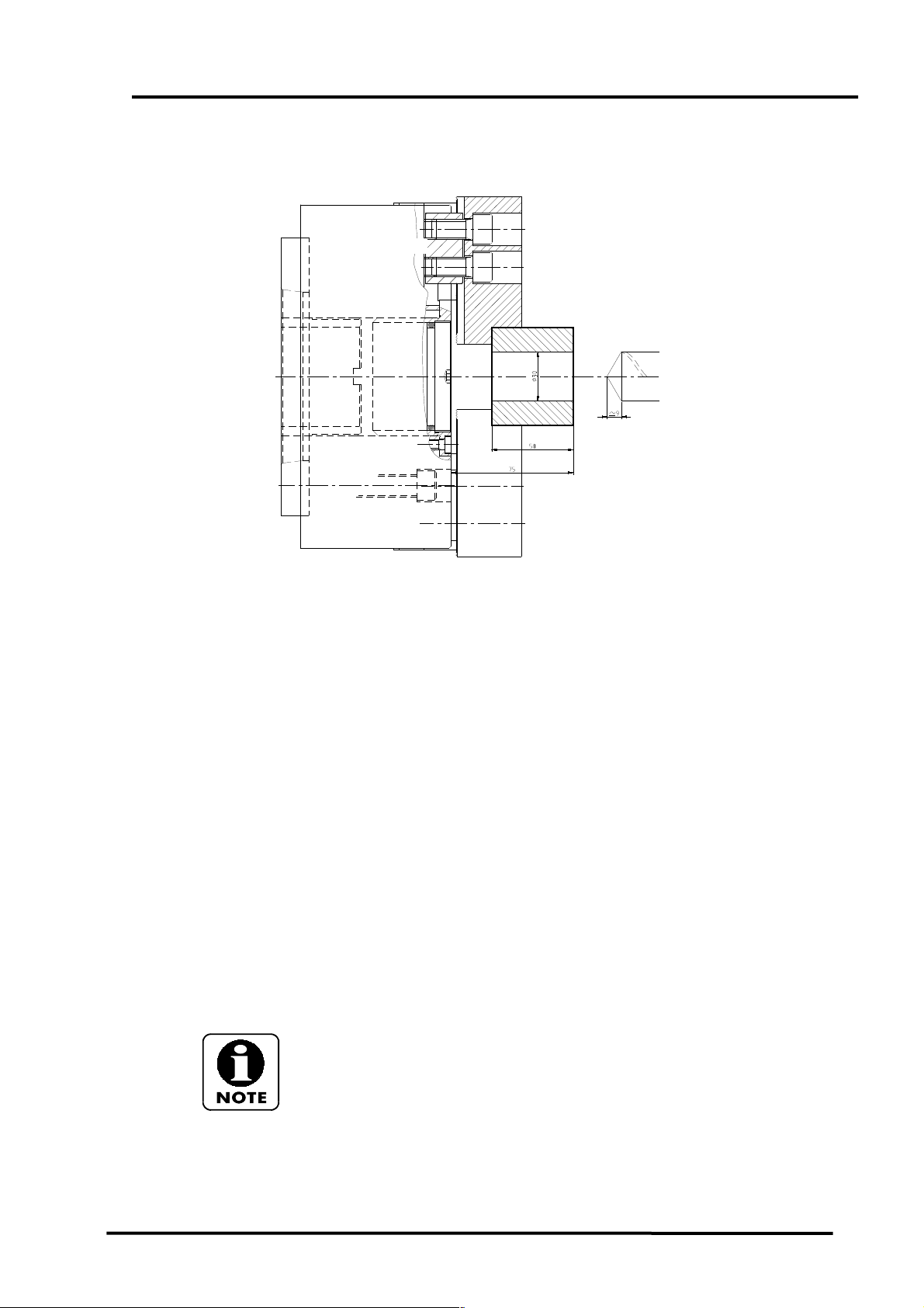
PROGRAMMING MANUAL -51-
6.2 G74 and G83 fixed drilling cycles (with chip breakage)
BBD 210
6.2.1 G74 Drilling cycle with a short retraction for chip breakage
O0009;
N10 G10 P0 Z-75;
N20 T808 (BORING TOOL OF 30);
N30 G97 S265 M4 F0.2 M8 M200; Fixed Revolutions of 265rpm Av=0.2mm per
revolution
N40 G0 X0 Z3; We place at X0 Z3
N50 G74 R0.5; Boring with breaking (removing 0.5mm)
N60 G74 Z-60 Q20000 F0.2; Bore until Z-60 depth: 20000 microns per
pass, Av=0.2mm per revolution
ATTENTION: in machines with specification of
“tenth of micron”, Q200000 must be set
instead of Q20000
N70 G0 X200 Z100 M30;
6.2.2 G83 Fixed drilling cycle with retraction at the start for chip breakage and removal
N40 G0 X0 Z3 M8; We place at X0 Z3
N50 G83 Z-60 Q20000 F0.2; Bore until Z-60, depth 20000 microns per
pass, Av=0.2mm per revolution
ATTENTION: in machines with specification of
“tenth of micron”, Q200000 must be set
instead of Q2000000
N60 G0 G80 X200 Z100 M30; Removing and ending
For retraction at the start, the end of program will be replaced by this end of
program; with cycle G83 the control retracts the drill to the start point (X0 Z3)
every time, thus the retraction (R05) is not entered.
Page 52
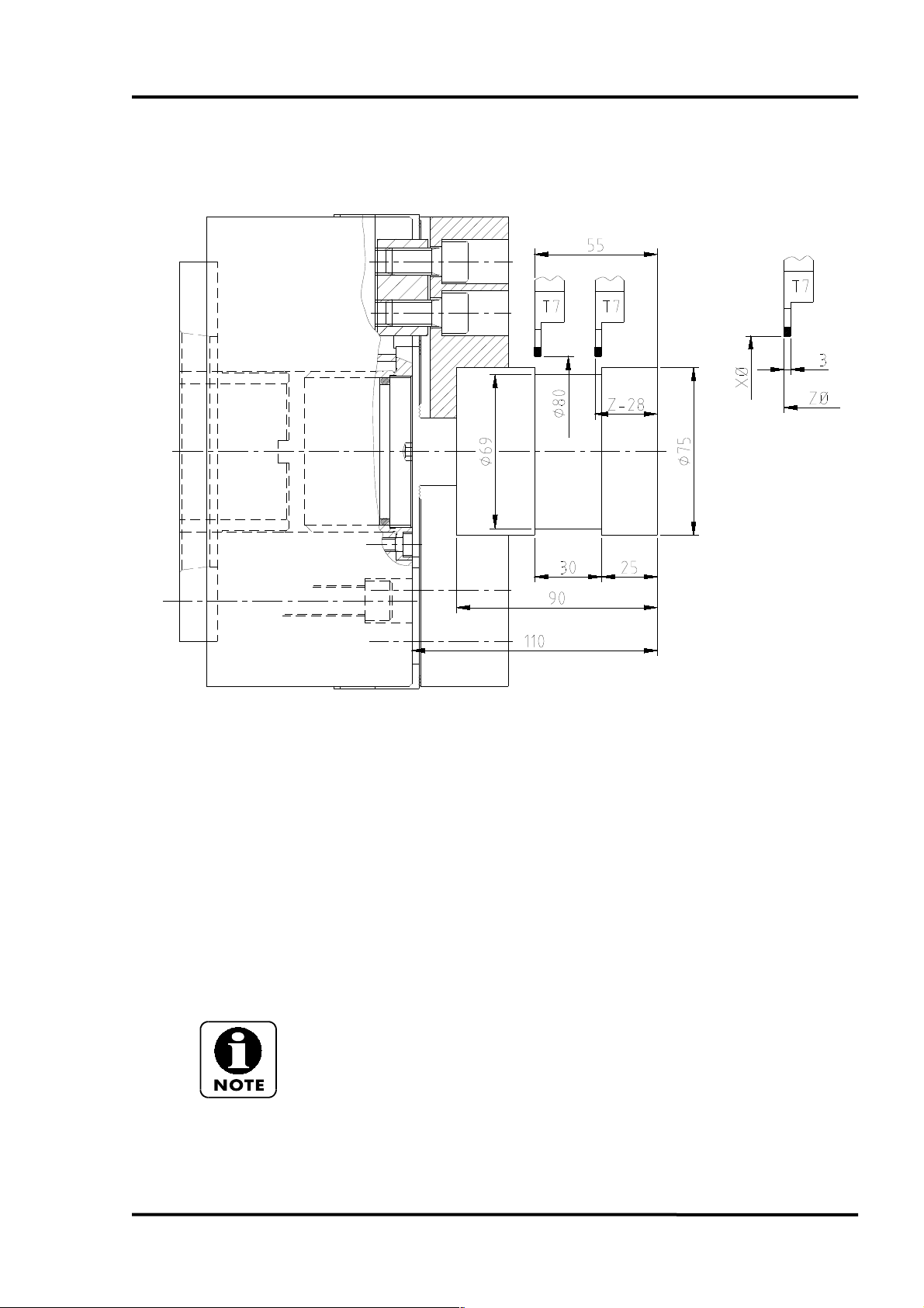
PROGRAMMING MANUAL -52-
6.3 Fixed longitudinal grooving cycle
BBD 210
O0010;
N10 G10 P0 Z-110;
N20 T707 (RANURADO);
N30 G50 S1000;
N40 G96 G99 S110 M4 M200 M8;
N50 G0 X80 Z-55; Positioning the TOOL at X80 Z-55
N60 G75 R.5; Grooving with chip breaking (0.5 of removing)
N70 G75 X69 Z-28 P3000 Q2500 F.1; Grooving, penetrate until ø69 and until Z(W)-28,
penetration in X 3000 microns, movement in Z
2500 microns Av=0.1mm/revolution
ATTENTION: in machines with specification of
“tenth of micron”, P30000 and Q5000 must be set
instead of P3000 y Q500
N80 G0 X200 Z200 M30;
Groove width or groove end point can be defined with a W code in this example
(W27, that is, 30 – 3 of tool), if tool is positioned on the right-hand would be (W-
27). For either Z or W, tool width must be subtracted.
Page 53
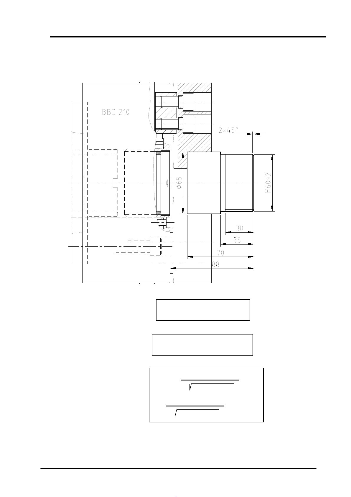
6.4 Threading fixed cycle
PROGRAMMING MANUAL -53-
Threading in 8 passes.
Thread height
Bottom diameter
1st pass cutting depth
P= 0.65 x 2 (thread pitch) = 1.3 mm
1300 microns
Ø = ønominal – ( 2 x height of threads)
Ø = 60 – (2 x 1.3) = 57.4
Q =
Thread height
Nr. of passes
Q =
1300 microns
=457 microns
8
Page 54

PROGRAMMING MANUAL -54-
O0011;
N10 G10 P0 Z-88;
N20 T101 (ROUNDING);
N30 G50 S2000;
N40 G96 G99 S200 F0.25 M4 M200 M8;
N50 G0 X68 Z0;
N60 G1 X-2;
N70 G0 X56 Z2;
N80 G1 Z0;
N90 X60 Z-2 F0.15;
N100 Z-35 F0.25;
N110 X66;
N120 G0 X200 Z100;
N130 T303 (ROSCADO);
N140 G97 S800 M4; Fixed revolutions at a 800 rpm
N150 G0 X62 Z4 (2 TIMES THE STEP); Positioning of TOOL.
N160 G76 P010060 Q50 R0.03; Threading fixed chicle P01/00/60: 01 passes,
N170 G76 X57.4 Z-30 R0 P1300 Q500 F2; Depth of thread ø57.4, end of thread Z-30,
N180 G0 X200 Z100 M30;
00 thread exit, 60 thread angle (60º)
ATTENTION: in machines with specification of
“tenth of micron”, Q500 must be set instead of
Q50
finishing offsets 0, thread height 1300
microns, depth of first pass 500 microns, pass
2
ATTENTION: in machines with specification of
“tenth of micron”, P13000 and Q5000 must be
set instead of P1300 y Q500
It must be kept in mind that in all cases when pitch is multiplied by the
revolutions the result must be ? 4000. Pitch x R.P.M. . 4000.
Page 55
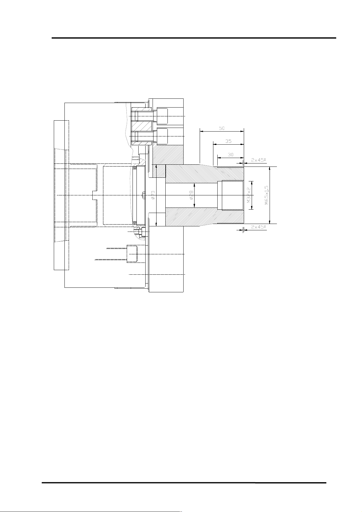
PROGRAMMING MANUAL -55-
6.5 Application exercise for threading operations
T1= OUTSIDE AND FACING.
T8= TWIST DRILL ø28
T10= BORING
T12= INTERNAL THREADING CUTTING
T5= EXTERNAL THREADING CUTTING
APPLY
DRILLING CYCLE
THREADING CYCLE
Page 56

PROGRAMMING MANUAL -56-
PROGRAM:
O0012;
N10 G10 P0 Z-100;
N20 T101;
N30 G50 S2000;
N40 G96 G99 S200 F0.2 M4 M8 M200;
N50 G0 X73 Z0;
N60 G1 X-2;
N70 G0 X61 Z2;
N80 G1 Z0;
N90 X64.9 Z-2 F0.15 (THREAD DIAMETER);
N100 Z-35 F0.2;
N110 X70 Z-50 F0.15;
N120 X71;
N130 G0 X150 Z200;
N140 T808 (BORE OF 28);
N150 G97 S300 M4 F0.15;
N160 G0 X0 Z3;
N170 G74 R1;
N190 G0 Z100;
N200 T1010 (INTERNAL MACHINING);
N210 G96 G99 S150 M4 F0.2;
N220 G0 X34 Z2;
N230 G1 Z0;
N240 X29.6 Z-2 F0.15;
N250 Z-30 F0.2;
N260 X27;
N270 G0 Z100;
N280 T1212 (INTERNAL THREAD);
N290 G97 S1300 M4;
N300 G0 X28 Z4 (2 TIMES THE LENGTH OF PASS);
N320 G76 X32 Z-25 R0 P1300 Q450 F2; ATTENTION: in machines with
specification of “tenth of micron”, P13000 and Q4500 must be set instead of
P1300 y Q450
N330 G0 X250 Z100;
N340 T505 (EXTERNAL THREADING);
N350 G97 S650 M4;
N360 G0 X67 Z3 (2 TIMES THE STEP);
N370 G76 P010060 Q50 R0.04; ATTENTION: in machines with specification of “tenth of
micron”, Q500 must be set instead of Q50
N380 G76 X63.05 Z-30 R0 P975 Q400 F1.5; ATTENTION: in machines with specification of
“tenth of micron”, P9750 and Q4000 must be set instead of P975 y Q400
N390 G0 X200 Z200 M30;
N180 G74 Z-84 Q30000 F0.15; ATTENTION: in machines
with specification of “tenth of micron”, Q300000 must be set
instead of Q30000
N310 G76 P010060 Q40 R0.03; ATTENTION: in machines
with specification of ·”tenth of micron”, Q400 must be
set instead of Q400
Page 57
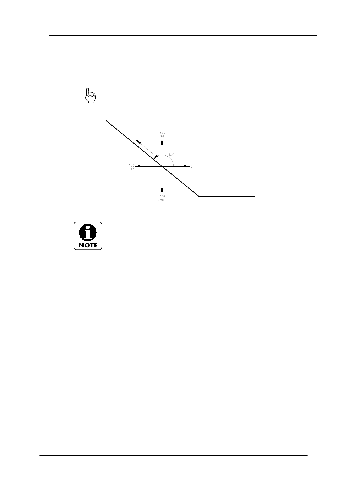
7. PROGRAMMING SIMPLIFICATION FUNCTIONS
Command and tool displacement tables are included in paragraph 13.6 of
Fanuc Manual, part 1/2.
PROGRAMMING MANUAL -57-
In theses cases, considering tool direction is most important.
The easier procedure is drawing a quadrant on the drawing and locate the
degrees as shown on the above diagram.
Page 58
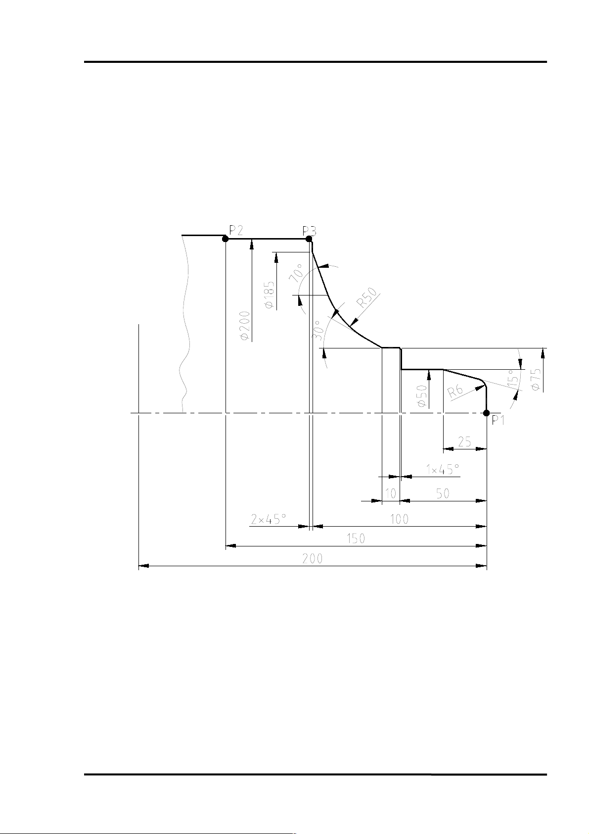
PROGRAMMING MANUAL -58-
7.1 Direct programming of profile (angles and round edges)
Page 59

PROGRAMMING MANUAL -59-
O0012;
N10 G10 P0 Z-200;
N20 T303 (PROFILING);
N30 G50 S2200;
N40 G96 G99 S230 F0.12 M4 M8 M200;
N50 G0 X0 Z3;
N60 G1 Z0 (P1);
N70 ,A90 R6 (FIRST ANGLE);
N80 X50 Z-25 ,A165 (SECOND ANGLE); A165 comes from 180°-15°=165°
N90 ,A180
N100 X75 Z-49 ,A90 ,C1;
N110 Z-60;
N120 ,A150 R50; A150 comes from 180°-30°=150°
N130 X185 Z-100 ,A110; A110 comes from 180°-70°=110°
N140 ,A90 ,C2;
N150 X200 Z-150 ,A180 (P2);
N160 G0 X250 Z200 M30;
Finishing on (P3):
N140 X200 C2;
N150 Z-102 (it is not known if right or left);
You can program two angles with 2 radii or bevels as a maximum.
7.2 Compensation function
For further information on this subject, refer to section 14 on Fanuc manual, part
1/2.
Page 60
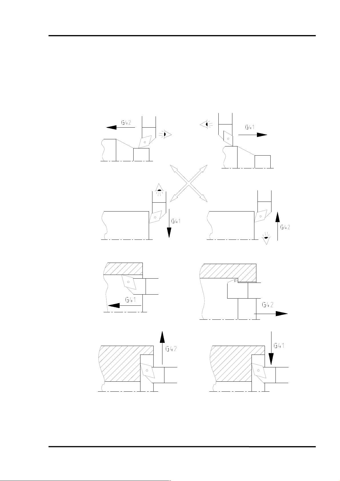
PROGRAMMING MANUAL -60-
7.2.1 Tool radius compensation
1st) Type of tool (Control) T (Offsets table).
2st) Radius inserts of tool (Control) R (Offsets table).
3st) Workpiece position with respect to tool (Part program) G41 or G42.
<EXTERNAL>
<INTERNAL>
Page 61
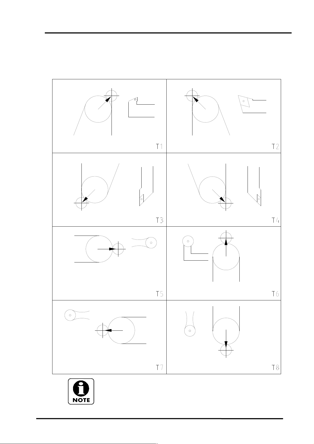
7.2.2 Tool types
PROGRAMMING MANUAL -61-
Milling cutters are assigned with type “0” or “9” for interpolations.
Page 62
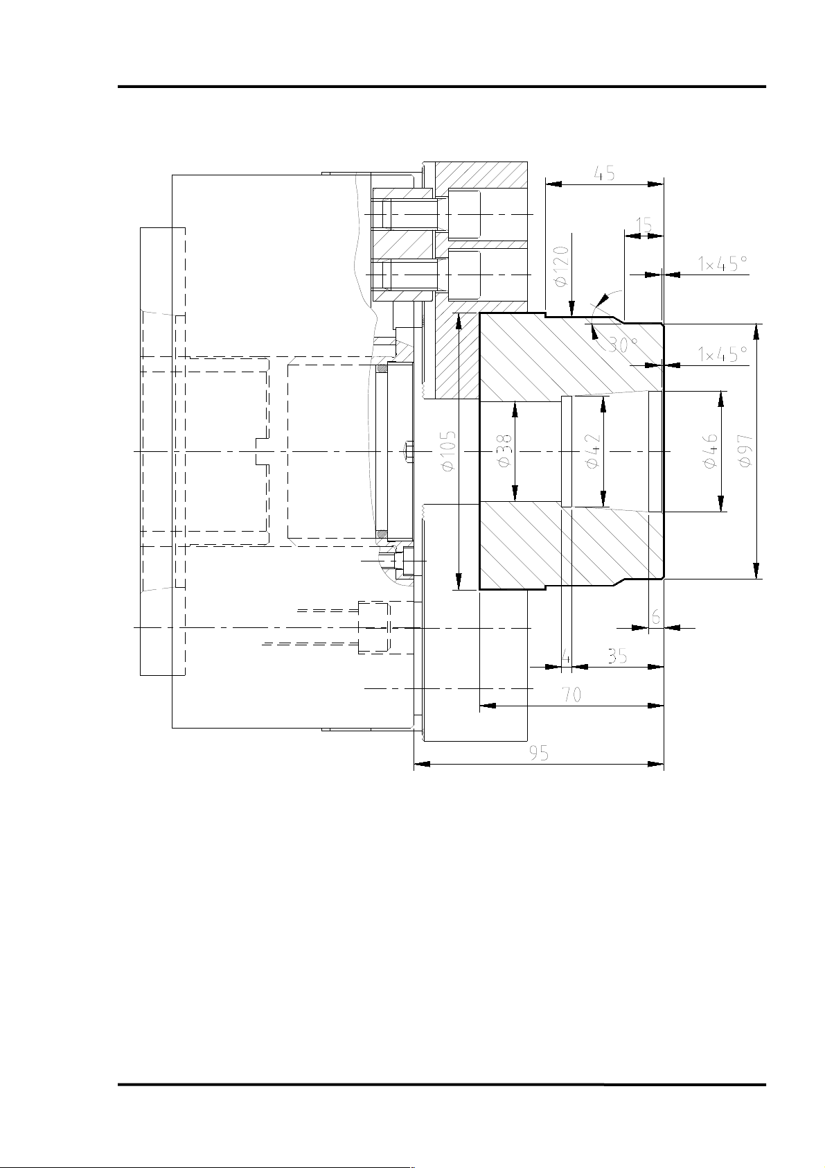
PROGRAMMING MANUAL -62-
7.3 G40 G41 and G42 tool radius compensation
Tools
T1 = EXTERNAL
T8= TWIST DRILL ø38
T10 = INTERNAL
Page 63

PROGRAMMING MANUAL -63-
O0013(TOOL RADIUS COMPENSATION G40, G41, G42);
N10 G10 P0 Z-95;
N20 T101 (EXTERNAL MACHINING);
N30 G50 S2200;
N40 G96 G99 S200 M4 F0.25 M8 M200;
N50 G0 X110 Z0;
N60 G1 X-2;
N70 G0 X100 Z2;
N80 G1 Z-17;
N90 G0 X102 Z3;
N100 G42 X95 Z1 (ACTIVES COMPENSATION RIGHTWARDS);
N110 G1 Z0;
N120 X97 Z-1 F0.15;
N130 Z-15 F0.2;
N140 A150;
N150 X102 Z-45 A180;
N160 X106;
N170 G0 G40 X200 Z200 (DISABLES COMPENSATION);
N180 T808 (BROCA DE 38);
N190 G97 S165 M4 F0.25;
N200 G0 X0 Z3;
N210 G74 R1 (BORING CYCLE);
N220 G74 Z-80 Q25000 F0.25; ATTENTION: in machines with specification of “tenth of
micron”, Q250000 must be set instead of Q25000
N230 G0 Z100;
N240 T1010 (INTERNAL MACHINING);
N250 G96 G99 S150 M4 F0.2;
N260 G0 X45 Z2;
N270 G1 Z-6;
N280 X41 Z-35;
N290 Z-38.9;
N300 G0 X37 Z4;
N310 G41 X48 Z2 (ACTIVES COMPENSATION LEFTWARDS);
N320 G1 Z0;
N330 X46 Z-1 F0.15;
N340 Z-6;
N350 X42 Z-35;
N360 Z-39;
N370 X37;
N380 G0 G40 X35 Z2 (DISABLES COMPENSATION);
N390 X200 Z150 M30;
Page 64
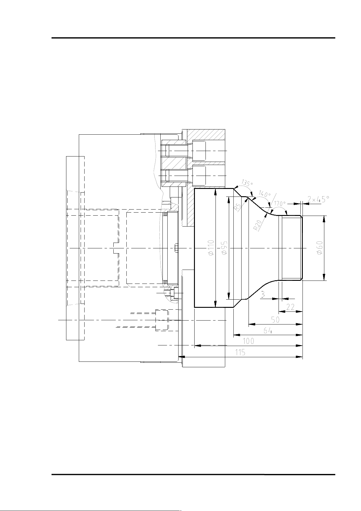
PROGRAMMING MANUAL -64-
7.4 G71 Type I - Example of roughing and finishing cycle with direct definition of profile and tool radius compensation
Page 65

PROGRAMMING MANUAL -65-
O0014 (Example of roughing cycle G71 Type I);
N10 G10 P0 Z-115;
N20 T101 (EXTERNAL ROUGHING);
N30 G50 S2500;
N40 G96 G99 S200 F0.25 M4 M8 M200;
N50 G0 X115 Z2.5;
N60 G1 X-2;
N70 G0 X115 Z5;
N80 Z0;
N90 G1 X-2;
N100 G0 X111 Z2 (POSITIONING, STARTOF CYCLE);
N110 G71 U3 R1 (ROUGHING CYCLE);
N120 G71 P1000 Q1100 U0.3 W0.1 F0.25;
N1000 G0 X56 (START OF PROFILE);
N1010 G1 Z0;
N1020 X60 Z-2;
N1030 Z-22;
N1040 A170 R20;
N1050 X95 Z-50 A140 R5;
N1060 A180;
N1070 X110 Z-64 A135;
N1100 X111 (END POINT OF PROFILE);
N130 G0 X200 Z100;
N140 T303 (EXTERNAL FINISHING);
N150 G96 G99 S230 M4 F0.15;
N160 G0 G42 X111 Z2 (POSITIONING START OF CYCLE);
N170 G70 P1000 Q1100 (FINISHING CYCLE);
N180 G0 G40 X200 Z100;
N190 T505 (THREADING);
N200 G97 S800 M4;
N210 G0 X62 Z4;
N220 G76 P010055 Q50 R0.025; ATTENTION: in machines with
specification of “tenth of micron”, Q500 must be set instead of Q50
N230 G76 X57.641 Z-19 R0 P1179 Q450 F1.814; ATTENTION: in machines with
specification of “tenth of micron”, P11790 and Q4500 must be set instead of P1179 and
Q450
N240 G0 X200 Z200 M30;
All cycles ends where they are started and, because of this, finishing positioning
is done above the workpiece.
Page 66
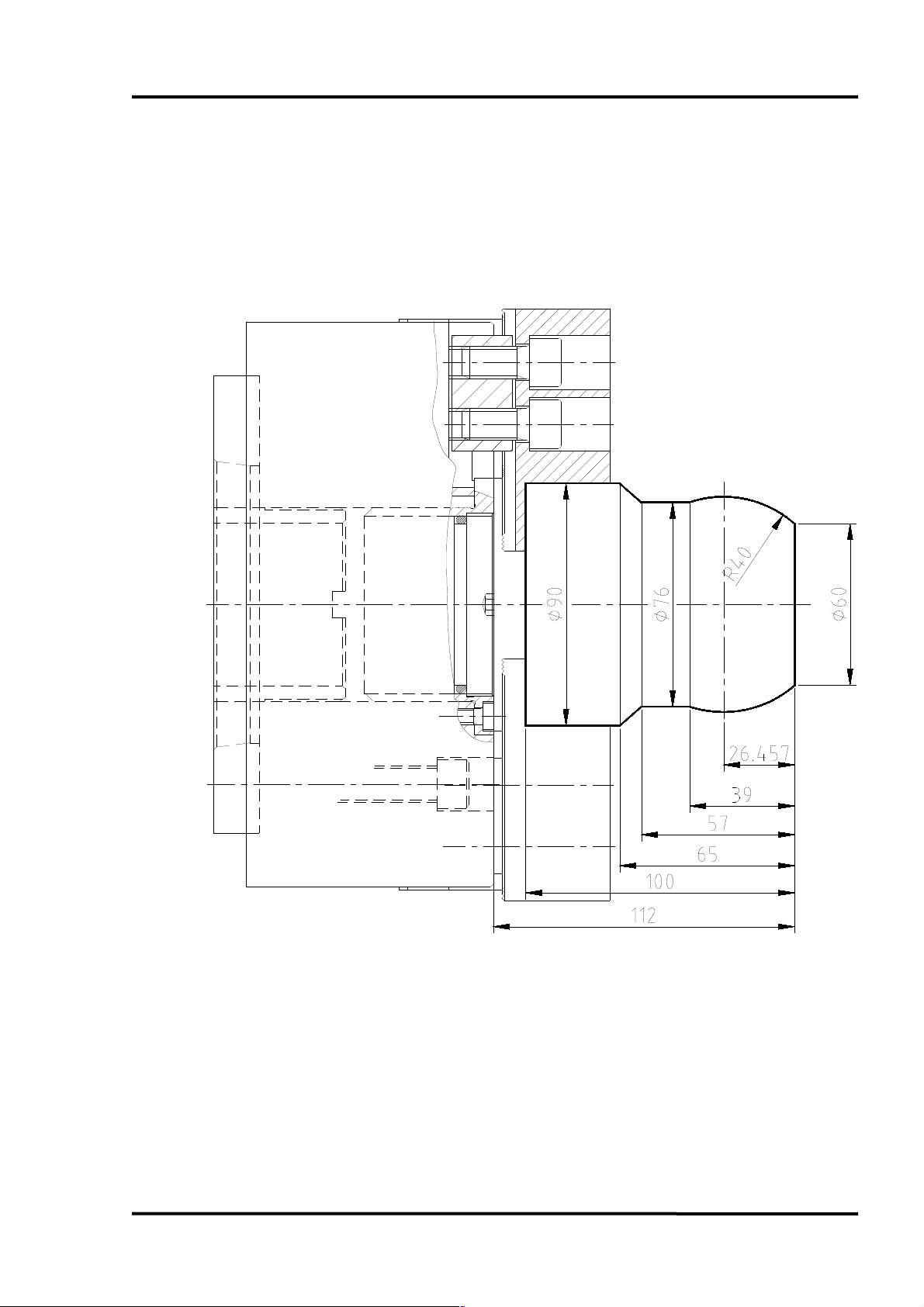
PROGRAMMING MANUAL -66-
7.5 G71 Type II - Roughing cycle with displacement direction reversal on X-axis
Page 67

O0016 (Example of roughing cycle G71 Type II)
N10 TI01 (ROUGHING);
N20 G50 S2200;
N30 G96 G99 S200 M4 F0.25;
N40 G0 X95 Z0 M8;
N50 G1 X-2 M38;
N60 G0 G42 X92 Z2;
N70 G71 U2.5 R1;
N80 G71 P1000 Q1500 U1.2 W0 F0.2;
N1000 G0 X60 W0;
N1010 G1 Z0;
N1040 G3 X76 Z-39 R40;
N1050 G1 Z-57;
N1500 X90 Z-65;
N90 G0 G40 X200 Z100;
N100 T303 (FINISHING);
N110 G0 G42 X92 Z2;
N120 G70 P1000 Q1500;
N130 G0 G40 X200 Z200 M30;
PROGRAMMING MANUAL -67-
For control units with capability for machining profiles with X-axis direction
reversal, the first block for defining the profile must state the movement of the
two axes or include “U0” or “W0”.
Roughing cycles are without tool radius compensation. Because of this, higher
allowances will be specified for X and Z depending on tool radius.
Page 68
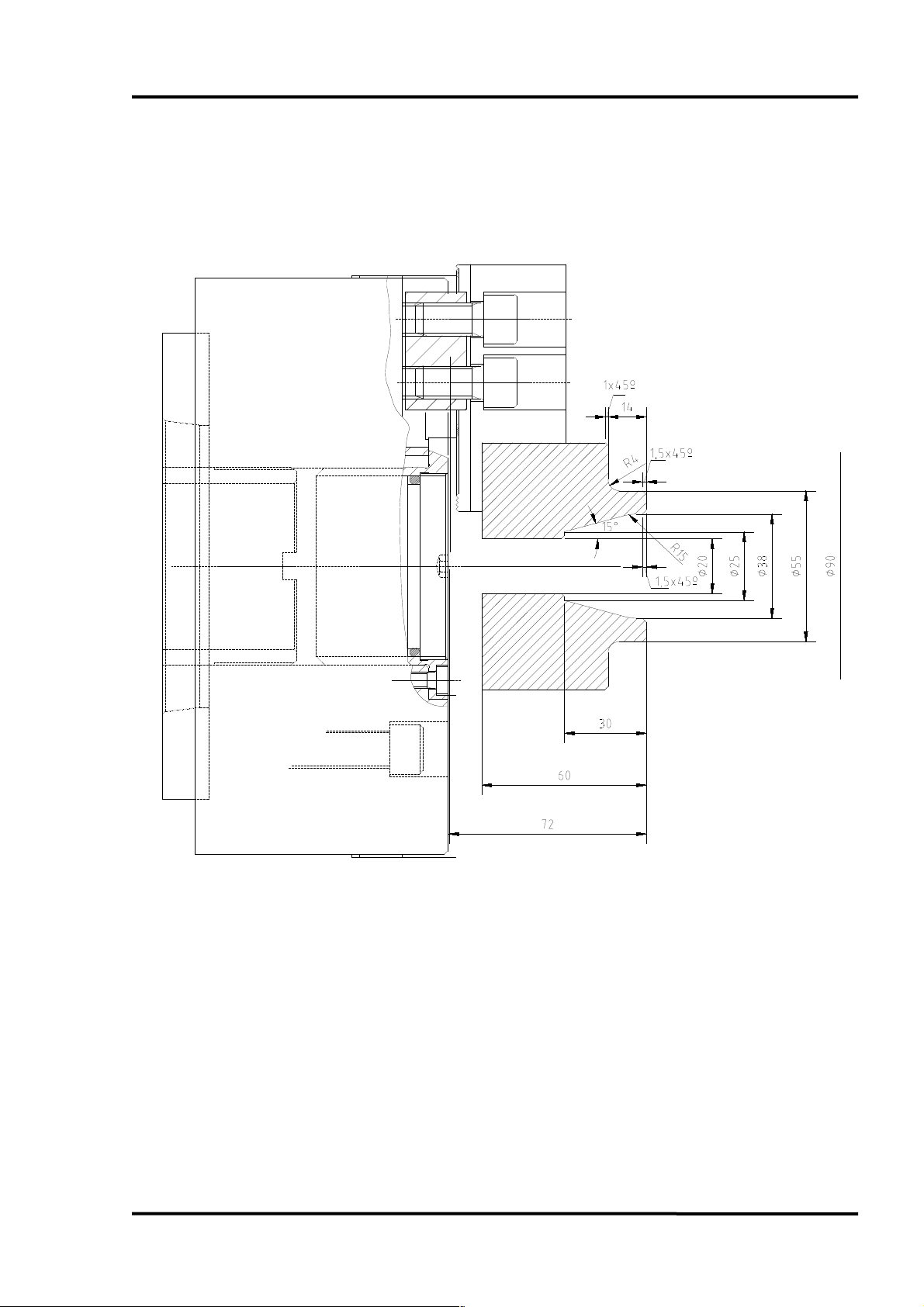
PROGRAMMING MANUAL -68-
7.6 G72 Example of cross roughing cycle parallel to X-axis
TOOLS:
T1 = EXTERNAL ROUGHING
T2 = EXTERNAL FINISHING
T6 = INTERNAL ROUGHING
T10 = INTERNAL FINISHING
Page 69

ROUGHING CYCLE APPLICATION
00017 (Example of roughing cycle G72);
N10 T101 (EXTERNAL ROUGHING);
N20 G50 S2200;
N30 G96 G99 S200 M4 F0,25;
N40 G0 X95 Z0 M8;
N50 G1 X18 M38;
N60 G0 X92 Z2;
N70 G72 W2.5 R1;
N80 G72 P1000 Q1200 U0.3 W0.15 F0.25;
N1000 G0 Z-15;
N1010 G1 X90;
N1020 X88 Z-1;4;
N1030 X55 R4;
N1040 Z-1.5;
N1200 X52 Z0;
N90 G0 X150 Z200;
N100 T606 (INTERNAL ROUGHING);
N110 G96 G99 S150 M4 F0.2;
N120 G0 X18 Z2;
N130 G71 U2.5 R1;
N140 G71 P2000 Q2100 U-0.3 W0.1 F0.2;
N2000 G0 X41;
N2010 G1 Z0;
N2020 X38 Z-1.5;
N2030 A180 R15;
N2040 X25 Z-30 A195;
N2050 X22;
N2100 X20 Z-31;
N150 G0 Z150;
N160 T1010 (INTERNAL FINISHING);
N170 G96 G99 S180 M4 F0.12;
N180 G0 G41 X18 Z2;
N190 G70 P2000 Q2100;
N200 G0 G40 X250 Z150;
N210 T303 (EXTERNAL FINISHING);
N220 G96 G99 S230 M4 F0.15
N230 G0 G41 X92 Z2
N240 G70 P1000 Q1200
N250 G0 G40 X200 M30
PROGRAMMING MANUAL -69-
Page 70
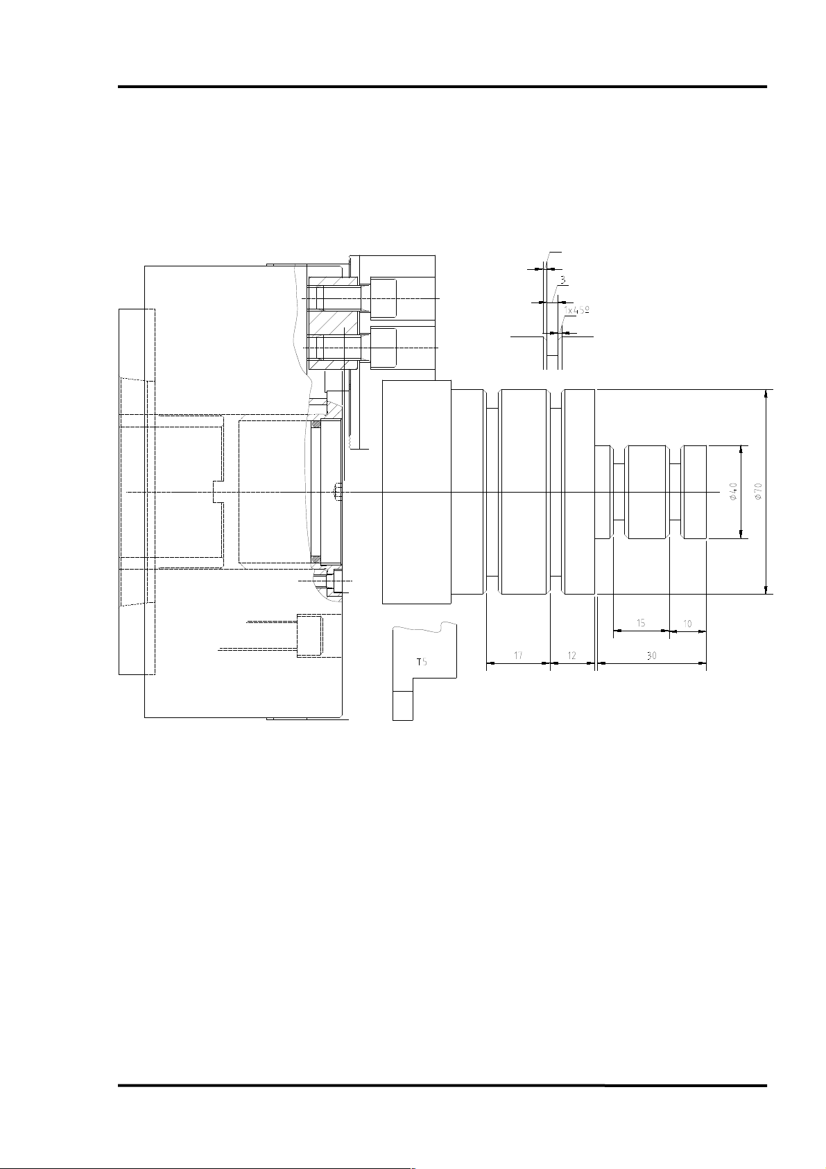
PROGRAMMING MANUAL -70-
7.7 M98 Repetitions of a subprogram
Page 71

SUBPROGRAM REPETITION APPLICATION
00015 (Repeating of subprogram M98);
N10 T505 (GROOVING);
N20 G96 G99 S100 M4 F0.1;
N30 G0 X74 Z-59 M8;
N40 M98 P1000 (CALLING TO SUBPROGRAM 01000);
N50 G0 Z-42;
N60 M98 P1000;
N70 G0 Z-25;
N80 X44;
N90 M98 P1000;
N100 G0 Z-10;
N110 M98 P1000;
N120 G0 X200 Z200 M30
SUBPROGRAM FOR A SLOT:
PROGRAMMING MANUAL -71-
01000 (SUBPROGRAM FOR THE SLOT);
N10 G1 U-12;
N20 G4 X1;
N30 G0 U12;
N40 W-1;
N50 G1 U-4;
N60 U-2 W1;
N70 G0 U6;
N80 W1;
N90 G1 U-4;
N100 U-2 W-1;
N110 G0 U6;
N120 M99 (END OF DE SUBPROGRAM);
The subprogram is called by means of command P followed by a number. This
number consists of four or more characters.
If the number consists of four characters, it indicates the identification number of
subprogram to be called.
If the number consists of more than four characters, the first four characters,
from right to left, indicate the identification number of subprogram to be called.
Next characters indicate the number of repetitions of subprogram to be called.
Page 72
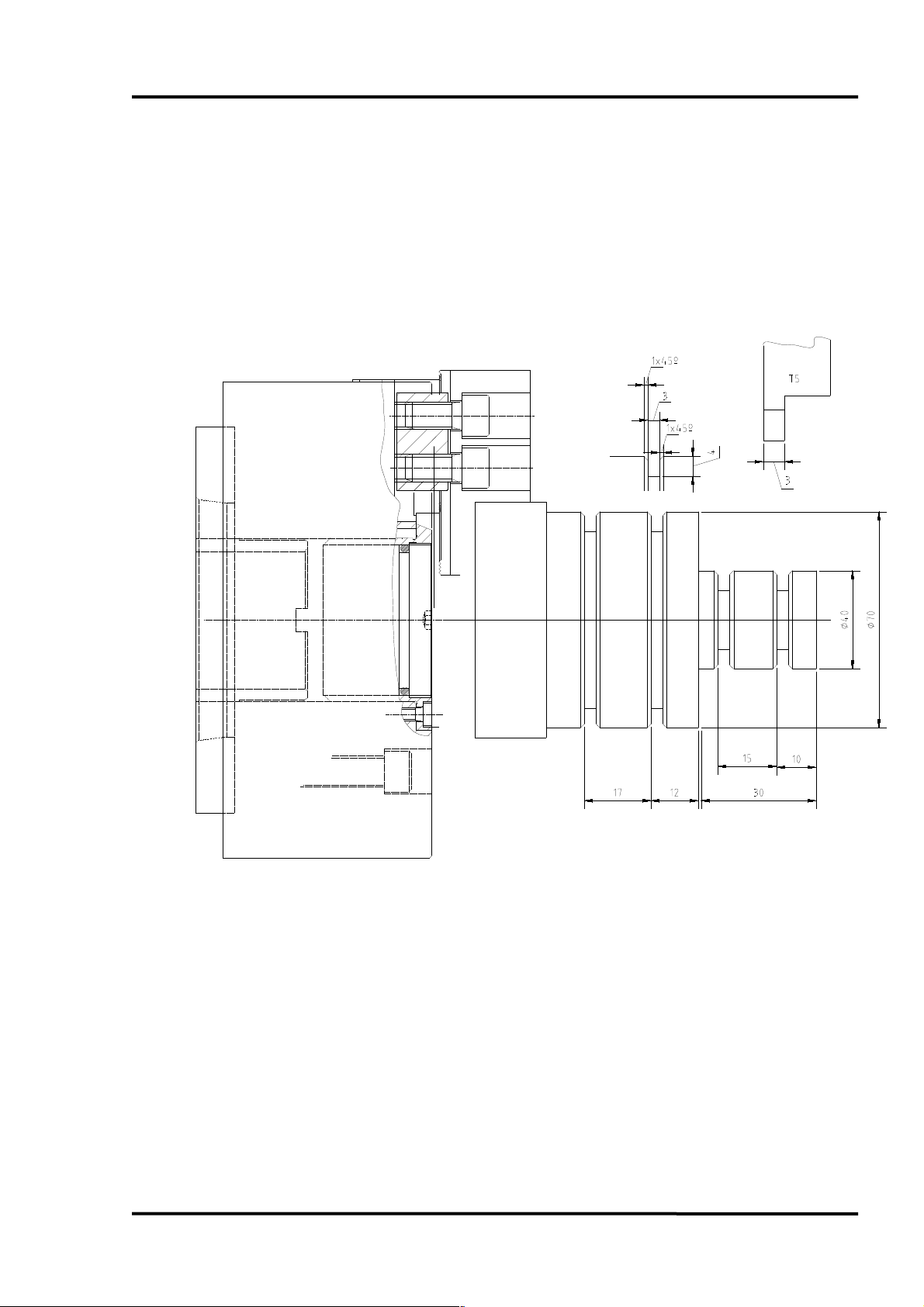
PROGRAMMING MANUAL -72-
7.8 M98 Repetition of parts of a program
Page 73

PARTS OF A PROGRAM REPETITION APPLICATION:
00018 (REPEATING OF PARTS OF A PROGRAM);
N10 T404 (GROOVING);
N20 G96 G99 S90 M4 F0.1;
N30 G0 X36 Z0 M8;
N40 M98 P41001 (REPEATS FOUR TIMES 1001);
N50 G0 X200 Z200
N60 M30
SUBPROGRAM FOR A SLOT:
O1001 (SUBPROGRAM FOR GROOVING);
N10 W-10
N20 G1 X30
N30 G4 X1
N40 G0 X36
N50 M99
PROGRAMMING MANUAL -73-
As described above, a subprogram or part of a subprogram is repeatedly called by means of a
command P followed by several numerical characters. In this example, the subprogram is
repeatedly called by means of “P41001”.
This command consists of three parts:
“P” calling a subprogram.
“4” number of subprogram repetitions.
“1001” number consisting of four characters and directly referring to the subprogram.
The maximum number of repetitions for a subprogram in a single call is
9999.
Page 74
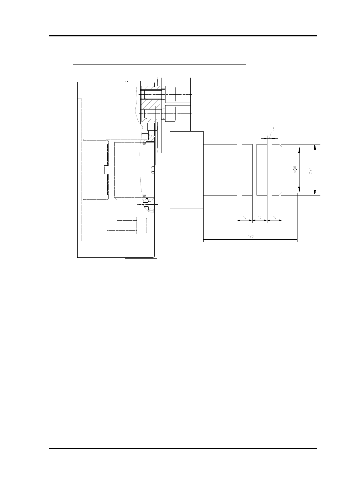
PROGRAMMING MANUAL -74-
OTHER EXAMPLE OF SUBPROGRAM EXECUTION REPETITION
PROGRAM:
O0001 (EXAMPLE OF M98);
N10 G10 PO Z-130;
N20 M98 P30002 (REPEATS 3 TIMES THE SUBPROGRAM 0002);
N30 G0 X150 Z150 M30
SUBPROGRAM
00002 (SUBPROGRAM);
N10 T101;
N25 G50 S1500;
N30 G96 S150 G99 F0.08 M4;
N40 G0 X30 Z-10;
50 G1 X-2;
N60 G0 X30;
N70 G10 P0 W10;
N80 M99
Page 75
PROGRAMMING MANUAL -75-
COMMAND
8. FIXED CYCLES BY CMZ
In this chapter, the description of some G codes that have been programmed by CMZ is
described
8.1 G38, Checking workpiece pushing
G38 is programmed when a workpiece clamped on the head is to be moved to the sub-head.
When transferring the workpiece from the head to the sub-head, it is assumed that the workpiece will
be in contact with sub-head chuck face when the limit value preset for B-axis is reached. Then the
workpiece is clamped on the sub-head and the program advances to the following block.
G38 can be only programmed on machines equipped with sub-head (S)
G38 B (J)_K_F_Q_;
- G38................Workpiece push checking command.
- B....................Absolute command
This is a B-axis coordinate value for the working position at
which the workpiece will be transferred from the head to the
sub-head.
- F....................Advance (mm/min)
This is the advance speed for workpiece transfer operation.
- Q....................Transfer position tolerance.
After the workpiece is positioned on B+Q as a result of transfer
operation, the program will be advanced to the following block.
This detection operation may cause an elongation of aluminium parts,
leading to permanent deformation or damage.
Transfer advance rate must be selected depending on workpiece
material and size.
1- If B-axis position after retracted from detected transfer position is out of the
specified tolerance “B+Q”, an alarm message will be displayed
3011 CYCLE NOT COMPLETED
and the machine will be stopped.
2- If Q value is omitted, the tolerance for workpiece position will be 1 mm.
3- The approach point specified before G38 must be a point located at a
distance of 1 mm from the sub-head chuck.
4- It is assumed that all coordinate values for B-axis are negative.
5- If any cycle argument is erroneous, the following alarm message will be
displayed:
3012 ILLEGAL COMMAND
Page 76

PROGRAMMING MANUAL -76-
EXAMPLE
Program with G38
This function is used to transfer a workpiece from the main head to the sub-head.
Workpiece push (torque) against sub-head chuck is checked during workpiece transfer
operation.
O0001;
N1;
Machining program
(Workpiece machined on main head)
N5;
G97 S1000 M03;.....................Main head rotates at 1000 min-1
M33;........................................Speed synchronisation
M211;......................................Open sub-head chuck jaws
G0 B-_;...................................Sub-head moved to B position (approach point) (machine co-
G98 G01 B-_F1000;................Sub-head approached to workpiece at 1000 mm/min-1 (Second
G38 B_F_Q_;..........................Workpiece push detection
ordinate system) (First approach)
approach)
Includes workpiece clamping operation on subhead.
G99;........................................Advance per revolution.
Machining program
(Cutting the workpiece)
M36;........................................Speed synchronisation disabled
G28 B0;...................................B-axis retracted to reference point.
M30;
Page 77
8.2 G138, workpiece clamping
COMMAND
This cycle can be replaced by G238 (refer to page 60)
G138 is programmed when a workpiece, which was previously clamped with main head, is to
be clamped with the tailstock (B-axis)
In the clamping operation, the workpiece is meant to be properly clamped when B-axis motor
torque reaches the limit value (cycle argument)
G138 is only available for machines equipped with automatic tailstock on B-axis
(T specification)
G138 B_ Q_ T_ S_ J_ E1 ....... Clamping
G138 D_ J_ E2 ....................... Releasing
PROGRAMMING MANUAL -77-
- G138.................Workpiece clamping command.
- B.........Absolute command
This is a B-axis coordinate value for the working final position
at which the workpiece will be clamped. This value should be
never reached by the tailstock
- Q.........Tolerance of final position for workpiece clamping (mm)
After the workpiece is positioned on B - Q as a result of
transfer operation, the program will be advanced to the
following block.
- T.........Limit torque for B-axis thrust (K/cm2).
- S.........Feedrate for final workpiece clamping (mm/min)
- D.........Feedrate for workpiece release (retraction) (mm/min)
- J..........Displacement on G1 when clamping and releasing a
workpiece.
- E.........Specifies tailstock displacement direction:
E1........Workpiece is clamed (advance).
E2........Workpiece is released (retraction).
This clamping operation may cause damage of aluminium parts, leading
to permanent deformation or damage.
Displacement and torque limit for clamping operation should be selected
according to workpiece material and dimensions.
1- If S value is omitted, the default advance value on clamping will be
200mm/min.
2- If D value is omitted, the default retraction value on clamping will be
1500mm/min.
3- If Q value is omitted, the tolerance for workpiece position will be 1mm.
4- If B-axis position after clamping a workpiece is out of the specified tolerance
"B-Q" an alarm message will be displayed:
3011 PART NOT CLAMPED
and the machine will be stopped.
Page 78
PROGRAMMING MANUAL -78-
5- “Workpiece clamped” signal is activated after reaching the torque limit and
current tailstock position is within tolerance "B-Q".
6- J value is optional; its default value, when J is not programmed, is: 5 mm.
7- If any cycle argument is erroneous, the following alarm message will be
displayed:
3012 ILLEGAL COMMAND
EXAMPLE
Clamping a workpiece on main head.
Workpiece push (torque) against centre piece is checked during workpiece clamping
operation.
O0001;
N1;
G138 B-425.8 Q1 S700 T300 J10 E1;...... Workpiece clamping cycle
G97 S1000 M03...................Main head rotates at 1000 rpm
G99; ....................................Advance per revolution.
Program with G138
Advance the tailstock to 10 mm on G0. From this position, the tailstock
must be advanced on G1 until reaching the torque limit with
F700mm/min.
The part will be clamping, if the B-axis position is between (B, B-Q].
If the B-axis final position is greater than “B-Q” (in the example,
-424.8mm), the alarm 3011 PART NOT CLAMPED will appear.
If the B-axis final position is less or equal to “B” (in the example,
-425.8mm), the alarm 3011 PART NOT CLAMPED will appear.
Machining program
G138 D1500 J10 E2; Workpiece releasing cycle
The tailstock is retracted 10 mm, as J is 10; with F1500mm/min.
M30;
Page 79
8.3 G238, workpiece clamping
COMMAND
G238 is programmed for clamping a workpiece, which was previously clamped on main head,
on the tailstock (B-axis).
In the clamping operation, the workpiece is meant to be properly clamped when B-axis motor
torque reaches the limit value (cycle argument)
G238 is only available for machines equipped with automatic tailstock on B-axis
(T specification)
G238 (X_ Z_) B_ K_ Q_ T_ S_ (A_) E1.............Clamping
G238 (X_ Z_) B_ D_ J_ E2.................................Releasing
- G238................Workpiece clamping command.
- X, Z.....Absolute command
These are the X and Z coordinate values for positioning the
axes on G0. This positioning is performed simultaneously with
B-axis.
- B.........Absolute command
This is a B-axis coordinate value for the working final position
at which the workpiece will be clamped. This value should be
never reached by the tailstock.
- Q.........Tolerance of final position for workpiece clamping (mm)
After the workpiece is positioned on B - Q as a result of
clamping operation, the program will be advanced to the
following block.
- T.........Limit torque for B-axis thrust (K/cm2).
- A.........T command for tool change it will be performed at the cycle
start.
- S.........Feedrate for final workpiece clamping (mm/min)
- D.........Feedrate for workpiece release (retraction) (mm/min)
- K.........Traverse on G1 when clamping the workpiece (mm).
- J..........Traverse on G1 when releasing the workpiece (mm).
- E.........Specifies tailstock displacement direction:
E1.......The workpiece is clamped (advance)
E2.......Workpiece is released (retraction).
PROGRAMMING MANUAL -79-
This clamping operation may cause damage of aluminium parts, leading to
permanent deformation or damage.
Displacement and torque limit for clamping operation should be selected
according to workpiece material and dimensions.
If S value is omitted, the default advance value on clamping will be:
200 mm/min.
If D value is omitted, the default retraction value will be:
1500 mm/min.
1- If Q value is omitted, the tolerance for workpiece position will be 1 mm.
2- If B-axis position after clamping the workpiece is out of the specified
tolerance “B,B-Q”, the following alarm message will be displayed:
3011 PART NOT CLAMPED
and the machine will be stopped.
Page 80
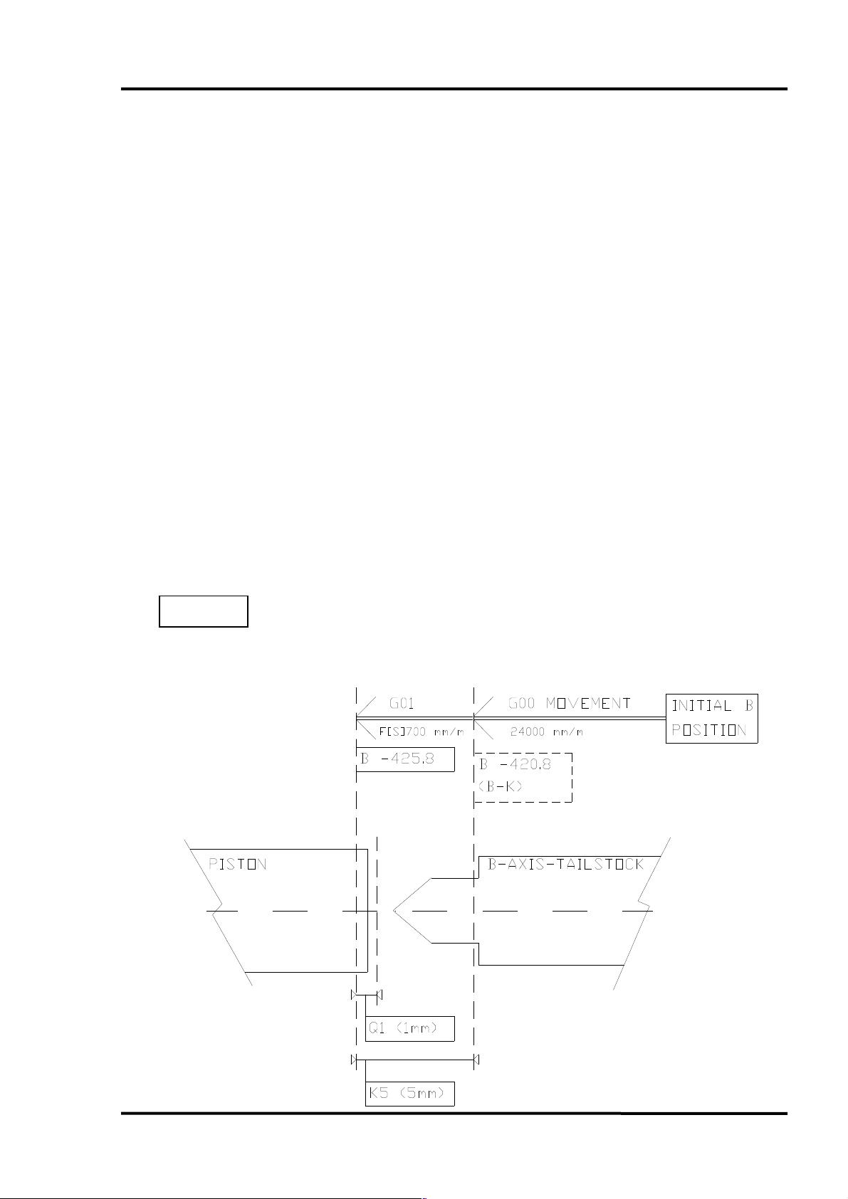
PROGRAMMING MANUAL -80-
3- “Workpiece clamped” signal is activated after reaching the torque limit and
current tailstock position is within tolerance "B,B-Q".
4- Programming X and Z arguments, for both clamping and releasing, is
optional.
5- If programmed, the positioning of X-, Z- and B-axis, when clamping or
releasing the workpiece, is simultaneous movement of 3 axes on G0.
6- Programming A argument is only possible during the clamping cycle and is
optional.
7- If K value is omitted, the default vale will be 10 mm. This value is only
effective on clamping cycle.
8- J value is optional, and is only effective during the releasing cycle its default
value, when B is not programmed, is: 0 mm.
9- When programming B on a releasing cycle, the J argument is optional. If J
is not programmed, the tailstock will go to B position programmed on G0
from the clamping position.
10- If B and J are programmed on a releasing cycle, the tailstock is retracted J
mm on G1 and then will go to B coordinate value programmed on G0.
11- If any cycle argument is erroneous, the following alarm message will be
displayed:
3012 ILLEGAL COMMAND
EXAMPLE
Clamping a workpiece on main head.
Workpiece push (torque) against centre piece is checked during workpiece clamping
operation.
Program with G238
Page 81
PROGRAMMING MANUAL -81-
O0001;
N1;
G238 X100 Z50 B-425.8 K5 Q1 S700 T250 A501 E1; .... Workpiece clamping cycle
The X, Z and B axes moving at the same time.
The tailstock is advanced to the B-position (-425.8+5=-420.8mm) on
G0, as K is 5 and B is –425.8. From this position, the tailstock is
advanced on G1 until reaching the torque, with F700mm/min, as S is
700.
After executing the part-clamping-movement, the new T code will be
executed.
The part will be clamping, if the B-axis position is between (B, B-Q].
If the B-axis final position is greater than “B-Q” (in the example,
-424.8mm), the alarm 3011 PART NOT CLAMPED will appear.
If the B-axis final position is less or equal to “B” (in the example,
-425.8mm), the alarm 3011 PART NOT CLAMPED will appear.
G97 S1000 M03..........................................Main head rotates at 1000 rpm
G99;............................................................Advance per revolution.
Machining program
G238 X250 Z250 B100 D1200 J10 E2; Workpiece releasing cycle
It will be moved 10 mm out from the workpiece, as J is 10; with F1200
mm/min.
Then it will be retracted on G0 to the X, Z and B coordinate values.
M30;
Page 82
PROGRAMMING MANUAL -82-
COMMAND
8.4 G384,G380 Rigid threading cycle
For threading operations, X- or Z-axis displacement per revolution of powered tool must be
equal to thread pitch.
To ensure that an accurate thread pitch is achieved, axis feed (X- or Z-axis) and powered tool
speed must be continuously synchronised.
A rigid threading cycle is disabled by entering G380 in the program.
Commands G384 and G380 can be only used on machines equipped with
powered tool.
< Rigid threading cycle on front end >
G384 X_C_Z_
H_R_F_S_D_M_E_Q_A_T2(T3);
< Rigid threading cycle on a side >
G384 X_C_Z_
H_R_F_S_D_M_E_Q_A_T1;
G380;
- G384..............Enables a rigid threading cycle
- G380..............Disables a rigid threading cycle
- X,Z,C..............Absolute command for positioning the tool in front of hole
centre.< Rigid threading on front end >
- R....................Used to set R point position (incremental value).
- H....................Specifies the position of hole bottom on X- or Z-axis from
point R (incremental value)
- F....................Used to set thread pitch (mm).
- S....................Used to set tool lead-in speed (min-1).
- D....................Used to set tool lead-out speed (min-1).
- A....................Specifies the command for t code, for selecting a new tool.
- M....................Used to activate head brake.
M50.............Brake of head or head 1.
M250...........Brake of head 2.
- T....................Used to set threading direction.
T1................Direction according to X-axis (threaded radial).
T2................Direction according to Z-axis (threaded axial <head 1>).
T3................Direction according to Z-axis (threaded axial <head 2>).
- Transmission ratio powered tool holder
E.................Tool holder input speed
Q.................Tool holder output speed.
If you press emergency stop or RESET pushbutton when a threading cycle is being executed, special attention
should be paid to axis movements, as otherwise damage could be
caused to the machine or workpiece. Executing G380 in MDI
Page 83

PROGRAMMING MANUAL -83-
1- For a threading cycle, axis and head override will be set to 100%.
2- Dry Run function is not available when a threading cycle is being executed.
3- Ensure that powered tool and head are stopped prior to executing a threading
cycle.
4- As axes and tool are synchonised, using a floating tap will not be required.
5- Powered tool speed will be limited when using a rigid threading cycle.
6 Positioning of X-, Z- and C-axis is performed on G0 simultaneously on the 3
axes. This movement is carried out when calling the cycle for the first time.
For subsequent calls, only a single coordinate value is possible. X or Z or C.
7- G384 function is programmed in all blocks requiring a rigid threading cycle. H,
R, F, S, D, M, Q, E, A and T values must not be entered in the second block in
which a rigid threading cycle is programmed, as well as in all subsequent
blocks. Only the position at which a threading operation is to be carried out must
be entered.
8- H argument is the distance from R point to hole bottom.
9- Entering the number of repeats for a rigid threading cycle is not permitted.
10- A rigid threading cycle enabled with G384 must be disabled with G380.
If another fixed cycle is entered without previously disabling a rigid threading
cycle, an alarm message (No. 3011) will be displayed. Indexing the turret with a
T command during a rigid threading cycle is not permitted.
If another fixed cycle is specified without previously cancelling the rigid threading
cycle, a collision between tool and workpiece may occur.
11- During a rigid threading cycle, turret indexing by means of command T is
carried out when starting the cycle and before positioning the axes.
12- If no D value is specified, tool lead-in and lead-out speed will be that
specified for S.
13- If neither M50 nor M250 is specified, there will be no head braking.
14- T3 value must be only specified for machins equipped with a sub-head (S).
This value must not be used to perform a front threading operation on a
workpiece located on the sub-head.
15- Commnad M250 will be only valid if a T3 value is specified.
16- If any cycle argument is erroneous, the following alarm message will be
displayed:
3012 ILLEGAL COMMAND
Page 84
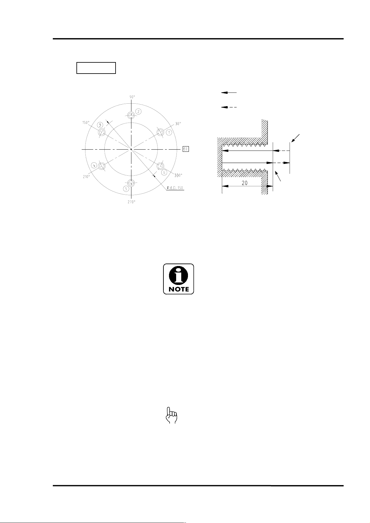
PROGRAMMING MANUAL -84-
EXAMPLE
Programming using G384 and G380
A rigid threading cycle (G384) (pitch: 2 mm; depth: 20 mm) is to be carried out for holes 1 to 6.
Infeed
Rapid displacement
Z30.0
(Initial point)
Normal rotation
Reverse rotation
Z15.0
(R point)
0.1 s dwell time on hole bottom
Movements for G384 on 1 - 6
O0001;
N1;
G98;........................................Advance per minute
M80;........................................C-axis on main head is activated
G28 H0;..................................Go to C-axis reference point
G97;........................................Constant head speed control is activated
Power tool is stopped
G384 X150.0 Z30.0 C30.0 H20.0 R15.0 F2.0 S300. D600. M50. T2. A101;
A rigid threading cycle is executed on point 1
- X150.0 Z30.0 C30.0
The axes are positioned on point 1 (X150, Z30, C30) at quick speed (G0).
- H20.0...........Position of hole bottom (from R)
- R15.0...........Position of R point (from initial point)
- F2.0.............Pitch: 2mm
- S300............Lead-in speed of powered tool: 300 min
- D600............Lead-out speed of powered tool: 600 min
- M50.............Main head brake
- T2................Threading direction (Z-axis direction <main head>)
- A101............Calling tool 01 with corrector 01.
-1
-1
When moving from initial point to R point, powered tool
rotation is stopped.
Page 85

PROGRAMMING MANUAL -85-
G384 C90.0;
G384 C150.0;
G384 C210.0; ...............
G384 C270.0;
G384 C330.0;
G380;......................................Rigid threading cycle is disabled (G384)
G00 X200.0 Z100.0 M05;........Powered tool is stopped.
M81;........................................C-axis is disabled.
G99;........................................Advance per revolution.
M30;
A rigid threading cycle (G384) is executed on
points 2 to 6
Page 86
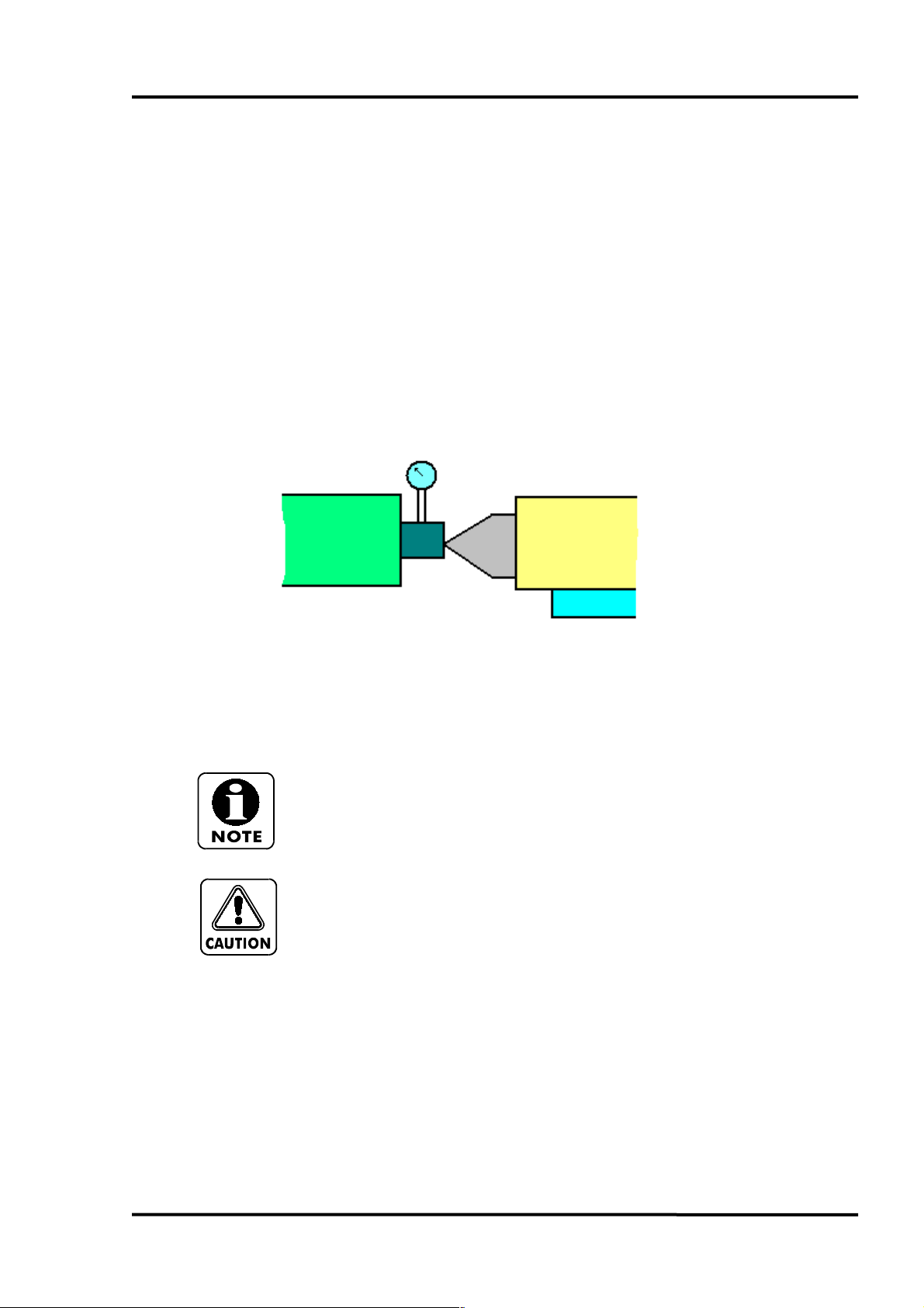
PROGRAMMING MANUAL -86-
8.4.1 Calibrating of tailstock pushing force.
G138 and G238 allow the calibrating of the tailstock pushing force through the variable #130.
When an argument T [Kgf] is programmed for this G function (limit of B axis pushing force),
the tailstock makes this force against the workpiece.
If a force meassurement device is installed between the spindle and the automatic tailstock, as
can be seen on next figure, the force made by the tailstock could be read. This force should be
the same as the one programmed on by the T argument.
Fig. 1.3.1
To calibrate this force, the variable #130 of the program O9016 (for the cycle G138), or the
program O9015 (for the cycle G238) can be introduced from the keyboard, until both
measurements are the same.
The initial #130 is introduced by the manufacturer during the machine
verification process.
If the bit 4 in the parameter 3202 takes the value of “1”, the edition of registered
programs O9000 to O9999 will not be possible.
Page 87
8.5 G384,G380 Rigid threading cycle
COMMAND
For threading operations, X- or Z-axis displacement per revolution of powered tool must be
equal to thread pitch.
To ensure that an accurate thread pitch is achieved, axis feed (X- or Z-axis) and powered tool
speed must be continuously synchronised.
A rigid threading cycle is disabled by entering G380 in the program.
Commands G384 and G380 can be only used on machines equipped with
powered tool.
< Rigid threading cycle on front end >
G384 X_C_Z_
H_R_F_S_D_M_E_Q_A_T2(T3);
< Rigid threading cycle on a side >
PROGRAMMING MANUAL -87-
G384 X_C_Z_
H_R_F_S_D_M_E_Q_A_T1;
G380;
- G384..............Enables a rigid threading cycle
- G380..............Disables a rigid threading cycle
- X,Z,C..............Absolute command for positioning the tool in front of hole
centre.< Rigid threading on front end >
- R....................Used to set R point position (incremental value).
- H....................Specifies the position of hole bottom on X- or Z-axis from
point R (incremental value)
- F....................Used to set thread pitch (mm).
- S....................Used to set tool lead-in speed (min-1).
- D....................Used to set tool lead-out speed (min-1).
- A....................Specifies the command for t code, for selecting a new tool.
- M....................Used to activate head brake.
M50.............Brake of head or head 1.
M250...........Brake of head 2.
- T....................Used to set threading direction.
T1................Direction according to X-axis (threaded radial).
T2................Direction according to Z-axis (threaded axial <head 1>).
T3................Direction according to Z-axis (threaded axial <head 2>).
- Transmission ratio powered tool holder
E.................Tool holder input speed
Q.................Tool holder output speed.
If you press emergency stop or RESET pushbutton when a threading cycle is being executed, special attention
should be paid to axis movements, as otherwise damage could be
caused to the machine or workpiece. Executing G380 in MDI
Page 88

PROGRAMMING MANUAL -88-
1- For a threading cycle, axis and head override will be set to 100%.
2- Dry Run function is not available when a threading cycle is being executed.
3- Ensure that powered tool and head are stopped prior to executing a threading
cycle.
4- As axes and tool are synchonised, using a floating tap will not be required.
5- Powered tool speed will be limited when using a rigid threading cycle.
6 Positioning of X-, Z- and C-axis is performed on G0 simultaneously on the 3
axes. This movement is carried out when calling the cycle for the first time.
For subsequent calls, only a single coordinate value is possible. X or Z or C.
7- G384 function is programmed in all blocks requiring a rigid threading cycle. H,
R, F, S, D, M, Q, E, A and T values must not be entered in the second block in
which a rigid threading cycle is programmed, as well as in all subsequent
blocks. Only the position at which a threading operation is to be carried out must
be entered.
8- H argument is the distance from R point to hole bottom.
9- Entering the number of repeats for a rigid threading cycle is not permitted.
10- A rigid threading cycle enabled with G384 must be disabled with G380.
If another fixed cycle is entered without previously disabling a rigid threading
cycle, an alarm message (No. 3011) will be displayed. Indexing the turret with a
T command during a rigid threading cycle is not permitted.
If another fixed cycle is specified without previously cancelling the rigid threading
cycle, a collision between tool and workpiece may occur.
11- During a rigid threading cycle, turret indexing by means of command T is
carried out when starting the cycle and before positioning the axes.
12- If no D value is specified, tool lead-in and lead-out speed will be that
specified for S.
13- If neither M50 nor M250 is specified, there will be no head braking.
14- T3 value must be only specified for machins equipped with a sub-head (S).
This value must not be used to perform a front threading operation on a
workpiece located on the sub-head.
15- Commnad M250 will be only valid if a T3 value is specified.
16- If any cycle argument is erroneous, the following alarm message will be
displayed:
3012 ILLEGAL COMMAND
Page 89
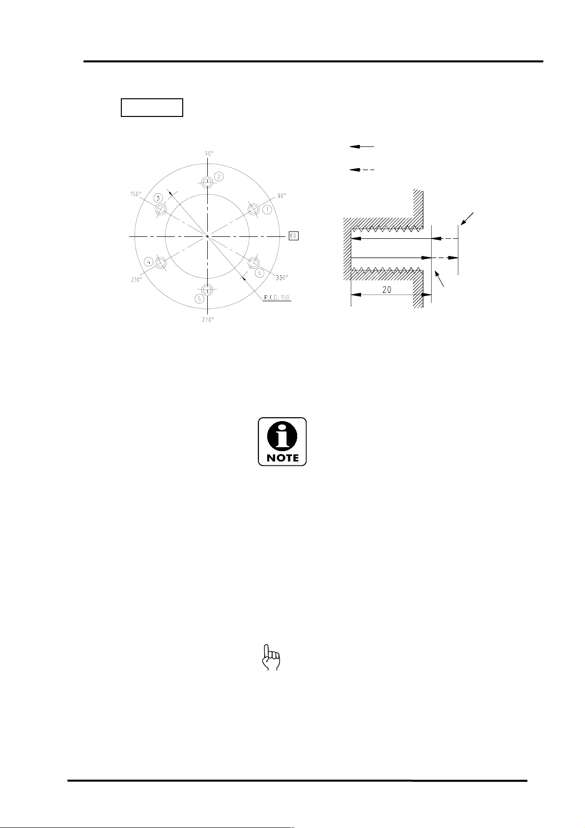
PROGRAMMING MANUAL -89-
EXAMPLE
Programming using G384 and G380
A rigid threading cycle (G384) (pitch: 2 mm; depth: 20 mm) is to be carried out for holes 1 to 6.
Infeed
Rapid displacement
Z30.0
(Initial point)
Normal rotation
Reverse rotation
Z15.0
(R point)
0.1 s dwell time on hole bottom
Movements for G384 on 1 - 6
O0001;
N1;
G98 (G94);..............................Advance per minute
M80;........................................C-axis on main head is activated
G28 H0;..................................Go to C-axis reference point
G97;........................................Constant head speed control is activated
Power tool is stopped
G384 X150.0 Z30.0 C30.0 H20.0 R15.0 F2.0 S300. D600. M50. T2. A101;
A rigid threading cycle is executed on point 1
- X150.0 Z30.0 C30.0
The axes are positioned on point 1 (X150, Z30, C30) at quick speed (G0).
- H20.0...........Position of hole bottom (from R)
- R15.0...........Position of R point (from initial point)
- F2.0.............Pitch: 2mm
- S300............Lead-in speed of powered tool: 300 min
- D600............Lead-out speed of powered tool: 600 min
- M50.............Main head brake
- T2................Threading direction (Z-axis direction <main head>)
- A101............Calling tool 01 with corrector 01.
-1
-1
When moving from initial point to R point, powered tool
rotation is stopped.
Page 90
PROGRAMMING MANUAL -90-
COMMAND
G384 C90.0;
G384 C150.0;
G384 C210.0; ...............
G384 C270.0;
G384 C330.0;
G380;......................................Rigid threading cycle is disabled (G384)
G00 X200.0 Z100.0 M05;........Powered tool is stopped.
M81;........................................C-axis is disabled.
G99 (G95);..............................Advance per revolution.
M30;
A rigid threading cycle (G384) is executed on
points 2 to 6
8.5.1 G100 Tailstock connect joint
When performing center-work, G100 Z_ moves the saddle to the position where the tailstock
can be connected to the saddle and then to the specified positioning point (Z_).
The G100 command can be used only with the programmable tailstock
specification machine.
G100 Z_ or G100 I1;
G100 …. Calls the tailstock connect joint mode
Z ……… Specifies the distance between the chuck face and the tailstock.
I1 ……… Specifies moving the tailstock to the parking position.
1/ Specify the G100 command independently in a block without other
commands.
2/ Specify the coordinate value of the tailstock positioning point (Z) in mm.
3/ For address Z, specify a numeric value with a decimal point.
4/ In order to get the tailstock out from the parking position the G100Z_
command should be commanded.
To execute the G100 command, the following conditions must be satisfied:
The main spindle or the rotary tool spindle is stopped.
The turret head index has completed.
The tailstock spindle is in the IN position.
During setup operation, it is recommended to record the position(s) where the
tailstock should be positioned and the position where the tailstock should be
returned after the completion of machining. The coordinate values must be
specified in the machine coordinate system.
Page 91
<Operation flow chart for G100>
EXAMPLE
<Macro program>
Positioning of the saddle to the tailstock joint position.
PROGRAMMING MANUAL -91-
...
G100 Z_;
...
Execution of M27 (tailstock body unclamp; joint pin extends from the
tailstock body to connect with the saddle).
Z_ (positioning of the tailstock at the position specified by Z_)
Execution of M28 (joint pin extracts from saddle to release the
tailstock body from the saddle ; tailstock body clamp).
Programming using G100
O0005;
N1;
G100 Z_; …………………………. Moving the tailstock to the position specified by Z_ (value in
mm).
M25; ……………………………… The tailstock spindle moves OUT to hold the workpiece by
the tailstock spindle center.
G04 U_; …………………………... Calling for dwell to allow positive support of the workpiece by
the tailstock spindle center.
G50 S1000:
T0101:
G96S100M03;
...
Machining program
…
G28 U0; …………………………. Machine zero return of X-axis to avoid interference with the
tailstock.
M05;
M26; …………………………….. The tailstock spindle moves IN.
G04 U_; …………………………. Calling for dwell to allow tailstock spindle to correctly extract
into the tailstock body.
G100 Z_; ………………………… Moving the tailstock to the previously located position,
specified by Z_ (value in mm).
…
Page 92
PROGRAMMING MANUAL -92-
COMMAND
8.5.2 G101 Tailstock connect joint
When performing center-work, G101 moves the saddle to the position where the tailstock can
be connected to the saddle and then the tailstock can be commanded to a working point.
The G101 command can be used only with the programmable tailstock
specification machine.
G101;
G101 …. Calls the tailstock connect joint mode
1/ Specify the G101 command independently in a block without other
commands.
To execute the G101 command, the following conditions must be satisfied:
The main spindle or the rotary tool spindle is stopped.
The turret head index has completed.
The tailstock spindle is in the IN position.
When programing G101 to get out the tailstock from park position, the joint hole
doesn’t change and the tailstock is coupled to the 2nd hole.
During setup operation, it is recommended to record the position(s) where the
tailstock should be positioned and the position where the tailstock should be
returned after the completion of machining. The coordinate values must be
specified in the machine coordinate system.
<Operation flow chart for G101>
<Macro program>
...
G101;
...
Positioning of the saddle to the tailstock joint position.
Execution of M27 (tailstock body unclamp; joint pin extends from the
tailstock body to connect with the saddle).
Page 93

PROGRAMMING MANUAL -93-
EXAMPLE
Programming using G101
O0005;
N1;
G101; …………………………. Moving the Z axis to the position where the tailstock was left.
G1Z_F100; ……………………….. Approuch the tailstock to the part with the Z-axis.
M28; ………………………..… Uncouple and clamp the tailstock.
M25; ……………………………… The tailstock spindle moves OUT to hold the workpiece by
the tailstock spindle center.
G04 U_; …………………………... Calling for dwell to allow positive support of the workpiece by
the tailstock spindle center.
G50 S1000:
T0101:
G96S100M03;
...
Machining program
…
G28 U0; …………………………. Machine zero return of X-axis to avoid interference with the
tailstock.
M05;
M26; …………………………….. The tailstock spindle moves IN.
G04 U_; …………………………. Calling for dwell to allow tailstock spindle to correctly extract
into the tailstock body.
G101; …………………………. Moving the Z axis to the position where the tailstock was left.
G1Z_F100; ……………………… Moving the tailstock to the previously located position
specified by Z_ (absolute coordinate value).
M28; ………………………… Uncouple and clamp the tailstock.
…
Page 94
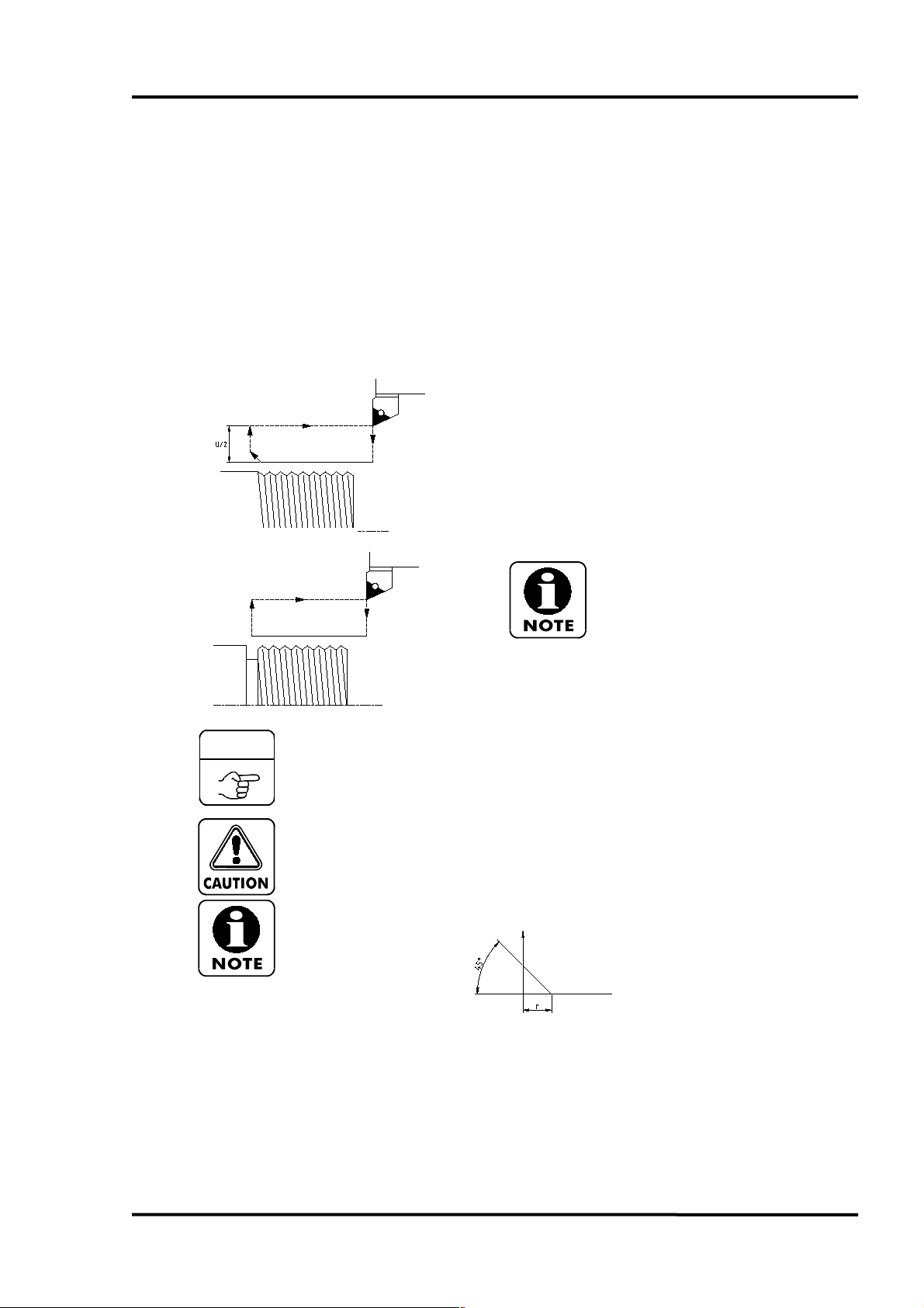
PROGRAMMING MANUAL -94-
COMMAND
9. M functions made by CMZ.
In this chapter, the description of some M functions that have been programmed by CMZ can
be found
9.1 M23,M24 Angular or straight thread runout
(1) Angular runout (M23)
(2) Straight runout (M24)
M23; ............ Used for angular runout.
M24; ............ Used for straight runout (disables angular runout).
M23 and M24 codes are used to specify an
angular or straight runout respectively for fixed
threading cycles.
If the thread is not relieved at the thread end, as
shown on the top left figure, a M23 function must
be programmed (aungular runout.
M24 function is used for threads relieved at the
thread end, as shown on the bottom left figure
(straight runout)
U/2 distance must be greater than
angular runout length ( r ). Refer to
bottom left figure.
Special care should be taken to prevent any interference between
workpiece and tool when using an angular runout.
As shown in the figure, r distance is programmed by means of parameter 5130.
Runout angle will be 45º.
Page 95
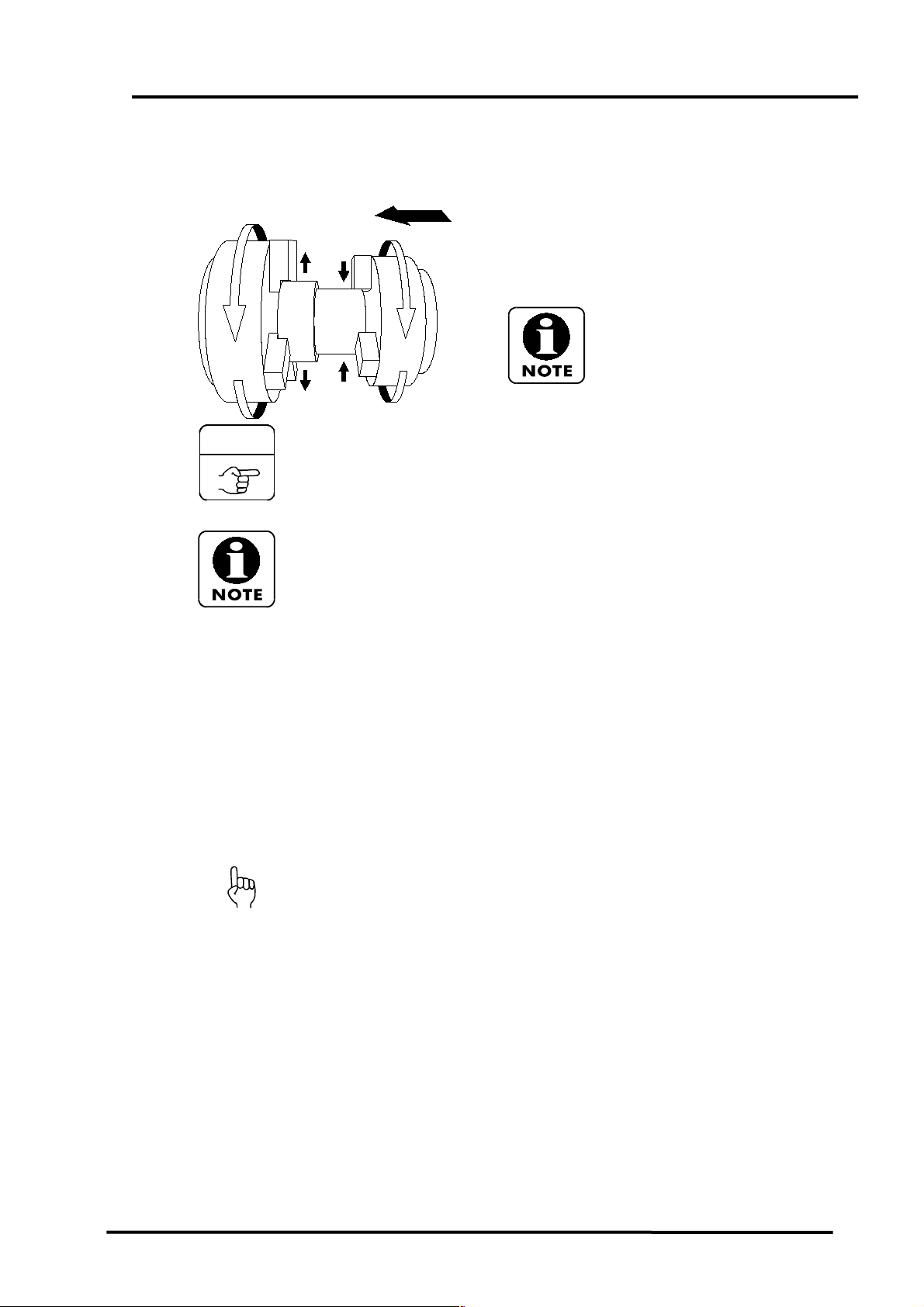
9.2 M33, M34, M36 Synchronising operation
COMMAND
M33 function is used to synchronise only head
and sub-head speed.
M34 function is used to synchronise head and
sub-head phase and speed.
M36 function disables the synchronisation mode.
M33; ............ Speed synchronisation.
M34; ............ Phase and speed synchronisation.
M36; ............ Synchronisation mode disabled.
PROGRAMMING MANUAL -95-
M33, M34 and M36 commands are
only used on machines equipped
with a sub-head (S).
1- For transferring a workpiece from main head to sub-head, head and subhead speed must be synchronised by means of M33 command. If the workpiece
is transferred without activating the synchronisation mode, scratching of
workpiece could result.
2- For transferring an hexagonal bar, head and sub-head phase and speed
must be synchronised by means of M34 command, as otherwise the transfer
operation will not be possible.
3- M36 function should be only programmed after completing a cutting cycle or
when chucks on main head and sub-head are open.
4- If a M34 function is programmed with sub-head jaws closed, alarm message
FM 102 will be displayed.
5- M5 function must not be programmed when phase and/or speed
synchronisation mode is activated. M5 function will disable the synchronisation
mode.
M34 function can de also used for round parts, but considering that phase (and
speed) synchronisation time is longer and speed synchronisation time, using
M33 function is recommended when machining round parts.
Page 96
PROGRAMMING MANUAL -96-
EXAMPLE
Program with M34 and M36 (1)
These functions are used when the workpiece on main head is to be transferred to sub-head
with the synchronisation mode activated.
O0001;
Machining program.
(machining operation on main head)
N5;
G97 S1000 M03;.....................Main head rotates at 1000 min-1.
M34;........................................Phase and speed synchronisation.
M211;......................................Sub-head jaws are opened.
After synchronising the phases, head and subhead speed is synchronised to 1000 min-1.
Sub-head rotates at 1000 min-1 in reverse direction with jaws
open.
During the synchronisation, heads can be rotated
with jaws open.
G53 B-_;.................................Sub-head is moved to limit point on B-axis (machine co-
ordinates)
(First approach)
G98 G01 B-_F1000;................Sub-head is approached to workpiece at a speed of 1000
mm/min
(Second approach)
G38 J_K_F_Q_;......................Workpiece push is detected.
Includes clamping of workpiece on sub-head.
G99;........................................Advance per revolution.
Machining program).
(Cutting operation)
M36;........................................Synchronisation mode is disabled
Sub-head is stopped while main head continues
rotating at programmed speed.
G28 B0;...................................Sub-head is returned to reference point on B-axis.
M01;
Page 97
PROGRAMMING MANUAL -97-
EXAMPLE
Program with M33 and M36 (2)
These functions are used when the workpiece on main head is to be transferred to sub-head
with the synchronisation mode activated.
O0001;
Machining program.
(machining operation on main head)
N5;
G97 S1000 M03;.....................Main head rotates at 1000 min-1.
M33;........................................Speed synchronisation.
Head and sub-head speed is synchronised to
1000 min-1.
M211;......................................Sub-head jaws are opened.
Sub-head rotates at 1000 min-1 in reverse direction with jaws
open.
During the synchronisation, heads can rotate with
jaws open.
G53 B-_;.................................Sub-head is moved to limit point in B-axis (machine co-
ordinates)
(First approach)
G98 G01 B-_F1000;................Sub-head is approached to workpiece at 1000 mm/min
(Second approach)
G38 J_K_F_Q_;......................Workpiece push is detected.
Includes clamping of workpiece on sub-head.
G99;........................................Advance per revolution.
Machining program.
(Cutting operation)
M36;........................................Synchronisation mode is disabled
Sub-head is stopped while main head continues
rotating at programmed speed.
G28 B0;...................................Sub-head is returned to reference point on B-axis
M01;
Page 98
PROGRAMMING MANUAL -98-
COMMAND
COMMAND
9.3 Spindles windings selection
The inetegrated spindles of machines TS and TS-Compact have two windings. By default the
selection of the spindles windings is automatic in the machine. But they can be selected using
the appropiate M codes in the part programm.
M310;............Automatic selection of main spindle windings.
M311; ..........Star-winding selection in main spindle.
M312; ..........Delta-winding selection in main spindle.
M320;...........Automatic selection of windongs in subspindle.
M321; ..........Star-winding selection in subspindle.
M322; ..........Delta-winding selection in subspindle.
In order to avoid any damage on machine, the work piece and the tools
and to make a correct machining of the work piece, is very important to
know the the torque and power characteristics of the wondings of the
spindles before executing any of the M codes described before.
Please look up the specifications manual sent with the machine.
1.- In machines without subspindle no execution of M320, M321 or M322 is
executed.
9.4 M40 Detection of cut workpiece
M40 function is used to check whether the cutting cycle on the workpiece transferred from
main head to sub-head is completed.
A cutting cycle is considered completed when sub-head speed is different to main head speed.
M40; ............ Detection of cut workpiece.
1.- M40 function can be only used on machines equipped with a sub-head (S).
2.- If the cutting cycle is not completed after executing a M40 function, the two
heads are stopped and alarm message FM41 (Cutting cycle not completed)
displayed.
3.- If a M40 function is executed with head synchronisation mode activated, the
head with the rotation is initiated (M3, M4, M203, M204) will rotate at
programmed speed. The other head will be stopped.
4.- Even though a M40 function disables head synchronisation, the operation
synchronisation mode is not disabled. Always enter a M36 function after
entering a M40 function in the program.
Page 99

O0001;
EXAMPLE
PROGRAMMING MANUAL -99-
Program with M40
Machining program
(Machining operation on main head)
N5;
G97 S1000 M03;.....................Main head rotates at 1000 min
-1
M33;........................................Speed synchronised in both heads.
M211;
Workpiece transfer
G99 G00 X42.0 M08;..............Advance per revolution
G01 X-06 F0.08;.....................Cutting cycle. Workpiece cut to X-0.6 at a feed speed of 0.08
mm/sec.
G28 U0 M09;
M40;........................................Detection of cut workpiece
Main head rotates at 1000 min-1 and sub-head is
stopped.
G28 W0;
M36;........................................Head synchronisation mode is disabled
G28 B0;...................................Sub-head is returned to reference point on B-axis.
M01;
Page 100
PROGRAMMING MANUAL -100-
COMMAND
9.5 M73, M74 Workpiece collector IN/OUT
When a M73 function is executed, workpiece collector is moved to a position under the chuck
in order to collect the finished workpiece.
When a M74 function is executed, workpiece collector returns to a position near machine door
for ejection of finished part.
If you try opening machine door, workpiece collector will be retracted to a position allowing the
door to be easily opened.
M73; ............ Workpiece COLLECTION.
(Workpiece collector IN)
M74; ............ Workpiece EJECTION.
(Workpiece collector OUT)
1.- Before executing a M73 function, ensure that the turret is out the
interference area with workpiece collector.
2.- Singly programming a M73 or M74 function in a block without any
other command and entering a G04 function in the next block, will allow
workpiece collector movements to be completed without any
interference.
If a G04 function is not entered in the next block, next block can be
started with workpiece collector not having completed its movements
and thus with a risk of collision.
G04 time period must be longer than the time required for collecting and
ejecting the workpiece. It should be taken also into account that this
time period will depend on air pressure.
3.- If workpiece weight or volume exceeds the capacity of workpiece
collector, do not use it, as otherwise damages could be caused to the
machine.
1.- On machines equipped with a sub-head (S), don not enter a M73 function in
the program if there is any risk of collision with sub-head body.
2.- On machines equipped with a sub-head (S), B-axis displacement is not
permitted when workpiece collector is in collection position.
 Loading...