

Page 1
Page 2

Terms and Conditions of Sale
LIMITED WARRANTY: Subject to the limitation specified herein, all parts included on
original equipment manufactured by CRANE MERCHANDISING SYSTEMS and sold to
purchaser are warranted for one year from the date of shipment of the equipment in
question. This warranty applies only to the original purchaser of the Merchandiser and is
null and void if the Merchandiser is sold during the period of warranty.
Defective parts will be repaired or replaced free of charge when the defective part is
returned, with transportation charges prepaid by purchaser, to a destination designated
by CRANE MERCHANDISING SYSTEMS.
This warranty does not include any cost of service rendered or repairs made by customer
or its agents on Merchandiser, or parts, unless authorization to incur such expense has
been given in writing by CRANE MERCHANDISING SYSTEMS prior to incurring such
expense. This warranty does not cover labor and service charges performed by CRANE
MERCHANDISING SYSTEMS service technicians.
This warranty does not apply to A) electrical components, wiring, or circuits or mechanical parts or assemblies damaged as a result of operating the Merchandiser at other than
the design voltage and frequency specified on the Electrical Rating Tag, or B) in event of
vandalism, fire or negligence, or C) incandescent lamps, neon lamps, fluorescent lamps,
ballasts, starters or other expendable items, or D) when seal is broken on electronic
boards, or E) when other manufactured components are installed in CRANE MERCHANDISING SYSTEMS Merchandisers.
Replacement parts sold by CRANE MERCHANDISING SYSTEMS as After Market shall
be covered for three months from the date shown on the parts invoice. Purchaser must
obtain prior RETURN AUTHORIZATION for return of all parts, following guidelines given
by CRANE MERCHANDISING SYSTEMS.
New, unused parts purchased as After Market can be returned within 30 days from date
of parts invoice, with prior authorization from CRANE MERCHANDISING SYSTEMS.
THIS WARRANTY IS IN LIEU OF ALL OTHER W ARRANTIES EXPRESS OR IMPLIED,
INCLUDING WITHOUT LIMITATION, WARRANTIES OF MERCHANTABILITY OF FITNESS FOR A P ARTICULAR PURPOSE. CRANE MERCHANDISING SYSTEMS SHALL
NOT BE RESPONSIBLE FOR CONSEQUENTIAL OR PUNITIVE DAMAGES. CRANE
MERCHANDISING SYSTEMS neither assumes nor authorizes any person to assume
for it any obligation or liability in connection with the sale of said equipment or any part
thereof.
Page 3

HotCup Operators’ Guide Table of Contents
Table of Contents
Specifications...................................................................................................................... 1
Major Parts .......................................................................................................................... 3
Controls and Indicators...................................................................................................... 7
Initial Setup........................................................................................................................ 13
Location Preparation.................................................................................................................. 13
Electrical Power Requirements.............................................................. .......... .......................... 13
Check the Power Outlet............................................................................................................. 13
Water Requirements.................................................................................................................. 14
Positioning the Merchandiser..................................................................................................... 14
Connecting Everything............................................................................................................... 15
Final Mechanical Preparation .................................................................................................... 16
Adjustments and Minor Maintenance......................................................................................... 30
Programming The HotCup............................................................................................... 34
Getting Around........................................................................................................................... 34
The Service Keypad................................................................................................................... 34
The Selection Switch Panel....................................................................................................... 34
The Displays.............................................................................................................................. 35
The Function Keys..................................................................................................................... 35
Other Keys................................................................................................................................. 36
Control Panel Switches Explained............................................................................................. 36
Programming Procedures ................................................................................................ 38
Some Conventions..................................................................................................................... 38
The Supervisor Mode................................................................................................................. 38
Gain Access to the Supervisor Mode......................................................................................... 38
Enter a New Supervisor Code ....................................................................................................39
Enter a FreeVend Code............................................................................................................. 39
Lock or Unlock Mode or Payout Keys........................................................................................ 39
Set Printer or Dex Options..........................................................................................................40
Lock or Unlock Data Clearing Access........................................................................................ 40
Select Display Language........................................................................................................... 40
Monetary Setup................................................................................................................. 41
Select Coin Mechanism and Options..........................................................................................41
Select Bill Validator and Options.................................................................................................42
Initial Setup of a Nonstandard Bill Validator................................................................................43
Select Monetary Options............................................................................................................ 43
Select Card Reader and Options............................................................................................... 44
Payout Coins.............................................................................................................................. 45
Set Up Winner Mode.................................................................................................................. 45
Set Up the Mug Discount........................................................................................................... 46
Set the Printer Baud Rate.......................................................................................................... 46
Disable Selections in the Merchandiser..................................................................................... 47
Assign Cup Sizes to Selections..................................................................................................48
November, 2007 i 6740001
Page 4

Table of Contents HotCup Operators’ Guide
Hot Drink Setup................................................................................................................ 49
Set Up A Hot Drink...................................................................................................................... 49
Whipper Options............................................................................................................... .......... 50
View or Set the Hot Water Tank Temperature............................................................................ 51
Set Up Low Temperature Dispensing........................................................................................ 51
Set Up Low Power Settings........................................................................................................ 52
Set the Ratio of Chocolate in Cappuccino.................................................................................. 53
Set the Brewer Rinse Time Interval........................................................................................... 53
Clear Tank Errors and Fill the Tank........................................................................................... 54
Set Up the Cup Only Option ...................................................................................................... 56
Product Configuration..................................................................................................... 58
Enter the Supervisor Code......................................................................................................... 62
Set the Machine to Vend a Large “D” Selection......................................................................... 62
Set Up Your Selection................................................................................................................ 62
Rinse the Brewer ....................................................................................................................... 66
Fill the Tank ............................................................................................................................... 66
PosiVend........................................................................................................................... 66
Set Up the PosiVend™ Anti-Jackpot Timer............................................................................... 67
View Number of Mug Vends...................................................................................................... 67
View Cup Ring Cycles Related to PosiVend™.......................................................................... 68
View Times No Cup Was Detected After a Cup Ring Cycled.................................................... 68
View Home Switch Usage Related to PosiVend™.................................................................... 68
View PosiVend™ Average Calibration Value ............................................................................ 69
Pricing............................................................................................................................... 70
Set the Price For a Cup Only..................................................................................................... 70
Set One Price for All Regular Size Drinks.................................................................................. 71
Set One Price for All Large Size Drinks..................................................................................... 71
Time Setup........................................................................................................................ 72
Set the Day of the Week............................................................................................................ 72
Set the Date and Year ............................................................................................................... 72
Set Time-of-Day Discount Vending............................................................................................ 73
Set Time-of-Day Free Vending.................................................................................................. 73
Messages.......................................................................................................................... 75
Select a Stand-by Message....................................................................................................... 75
Select a FreeVend Message...................................................................................................... 76
The End of Message Character................................................................................................. 77
The Character Set...................................................................................................................... 78
Testing............................................................................................................................... 79
Test the Display......................................................................................................................... 79
Test the Cup Mechanism........................................................................................................... 79
Test the Whippers...................................................................................................................... 80
Test the Air Compressor............................................................................................................ 80
Test Various Sensors and Switches.......................................................................................... 81
Rinse All Mixing Bowls............................................................................................................... 81
6740001 ii November, 2007
Page 5

HotCup Operators’ Guide Table of Contents
View Machine Info............................................................................................................. 82
View Discount Sales by Time Interval........................................................................................ 82
View Free Vends........................................................................................................................ 82
View Winners............................................................................................................................. 82
View Total Unpaid Vends........................................................................................................... 84
View Number of Test Vends...................................................................................................... 84
View Sales Data By Price.......................................................................................................... 84
View Machine ID number............................................................................................ .......... ..... 85
View Non-Resettable Sales and Vend Data.............................................................................. 85
View Total Paid Sales................................................................................................................ 86
View Card Reader Paid Sales ................................................................................................... 86
Clear All Resettable Data........................................................................................................... 87
Clear Paid Sales Data Only....................................................................................................... 87
View Amount in Coin Box .......................................................................................................... 87
View Diagnostic Messages........................................................................................................ 88
Change Machine ID Number ..................................................................................................... 91
View the Water Tank Temperature............................................................................................ 91
View the Current Software Version Number.............................................................................. 91
View the Selection Machine Type.............................................................................................. 91
View the Selection Configuration............................................................................................... 92
Sanitation........................................................................................................................... 93
Basics ........................................................................................................................................ 93
Introduction................................................................................................................................ 93
Cleaning and Sanitizing -- What’s the Difference? .................................................................... 93
How Do I Sanitize? .................................................................................................................... 93
A Good Place to Start -- Your Sanitation Kit.............................................................................. 94
Sanitation Procedures................................................................................................................ 94
Overall Cleaning ...................................................................................................................... 100
Preventative Maintenance Cleaning........................................................................................ 101
Appendix A
The Optional Printer.................................................................................................................. A-1
Appendix B
The Infrared Mug/Cup Sensor .................................................................................................. B-1
Appendix C
DEX/UCS Interface Operation.................................................................................................. C-1
Appendix D
Modify Canister to Vend 12oz Cups ........................................................................................ D-1
Appendix E
Clean Hot Water Tank .............................................................................................................. E-1
Appendix F
The FreeVend Keyswitch Option.............................................................................................. F-1
November, 2007 iii 6740001
Page 6

Table of Contents HotCup Operators’ Guide
6740001 iv November, 2007
Page 7

HotCup Operators’ Guide Specifications
Specifications
SPECIFICATIONS COMMON TO ALL MACHINES
DIMENSIONS 72" (183 cm) high
32" (81 cm) wide
28.5" (72 cm) deep
WEIGHT 475 lbs (215.5 kg)
WATER REQUIREMENTS Minimum: 20 psi (137.8 kPa)
Maximum: 80 psi (551.2 kPa)
AMBIENT
TEMPERATURE
OPERATING
ENVIRONMENT
CUP CAPACITIES
(APPROXIMATE)
Minimum: 41° F (5° C)
Maximum: 90° F (32° C)
For indoor use only
5 oz cups - 965
7 oz cups (squat) - 805
8.25 oz cups - 735
9 oz cups (squat) - 770
10 oz cups - 690
12 oz cups - 660
CANISTER CAPACITIES
(APPROXIMATE)
Fresh brew coffee - 13 lbs (Model 6
Freeze dry coffee - 2 lbs
Fresh brew decaf - 9 lbs (Model 6
Freeze dry decaf - 2 lbs
Tea (freeze dry) 1.5 lbs
Chocolate - 10 lbs
Soup (or sugar substitute) - 6.7 lbs (4 lbs)
Sugar - 11 lbs
Lightener - 4.5 lbs
PRODUCT OPTIONS
Model 67
4 Fresh Brew Standard Configuration:
Fresh brew coffee (pre-ground)
Fresh brew OR freeze dry decaf
Freeze dry tea
Espresso, cappuccino, hot chocolate, and "cup only" selections
Optional Configurations:
Hot water selection
Soup selection
OR
Sugar substitute condiment
74 only)
74 only)
Model 67
6 Freeze Dried Standard Configuration:
Freeze dry coffee
Freeze dry decaf
Freeze dry tea
Espresso, cappuccino, hot chocolate, and "cup only" selections
Optional Configurations:
Hot water selection
Soup selection
OR
Sugar substitute condiment
November, 2007 1 6740001
Page 8
Specifications HotCup Operators’ Guide
SPECIFICATIONS COMMON TO ALL MACHINES (CONTINUED)
OPTIONS
ELECTRICAL
Automatic delivery door
Base grille kit (1 sided)
Base grille kit (3 sided)
Coin box lock
Data printer kit
Debit card reader
Door striping kit
Everpure water filter kit
Cuno water filter kit
Hydro-Life water filter kit
Soup whipper kit
Flex Ace door lock and key
Van door lock and key
Free vend keyswitch
Snap-on ingredient canister extension sleeves (4" tall)
Sugar substitute
Ingredient rinse tray
Cup/mug electronic sensor (cup hold switch kit)
PosiVend
Hot water selection kit
Filter paper kit (2400 vends per roll) for brewer (Model 6
Choice of ""Textured white"" or ""Textured gray"" paint for cabinet door
SPECIFICATIONS UNIQUE TO 115 VOLT MACHINES
115 Volts AC
60 Hertz
12 Amps
Single phase
74 only)
COIN MECHANISM
BILL VALIDATORS
SPECIFICATIONS UNIQUE TO 220 - 240 VOLT MACHINES
ELECTRICAL
COIN MECHANISM
OPTIONS AND ACCESSORIES
MARS TRC-6000
COINTRON 3000
MARS TRC-6010XV (24 V)
Maka/Conlux Model USPX-004 (24 V)
Coin Acceptors Model 9302-LF (24 V)
MARS VFM1 pulse
MARS VFM3 serial
MAKA pulse
COINCO
MDB
220 - 240 Volts AC
50 Hertz
10 Amps
2 kW
Single phase
OPTIONS AND ACCESSORIES
Executive coin mechanism interface
6740001 2 November, 2007
Page 9
HotCup Operators’ Guide Major Parts
POINT OF
K
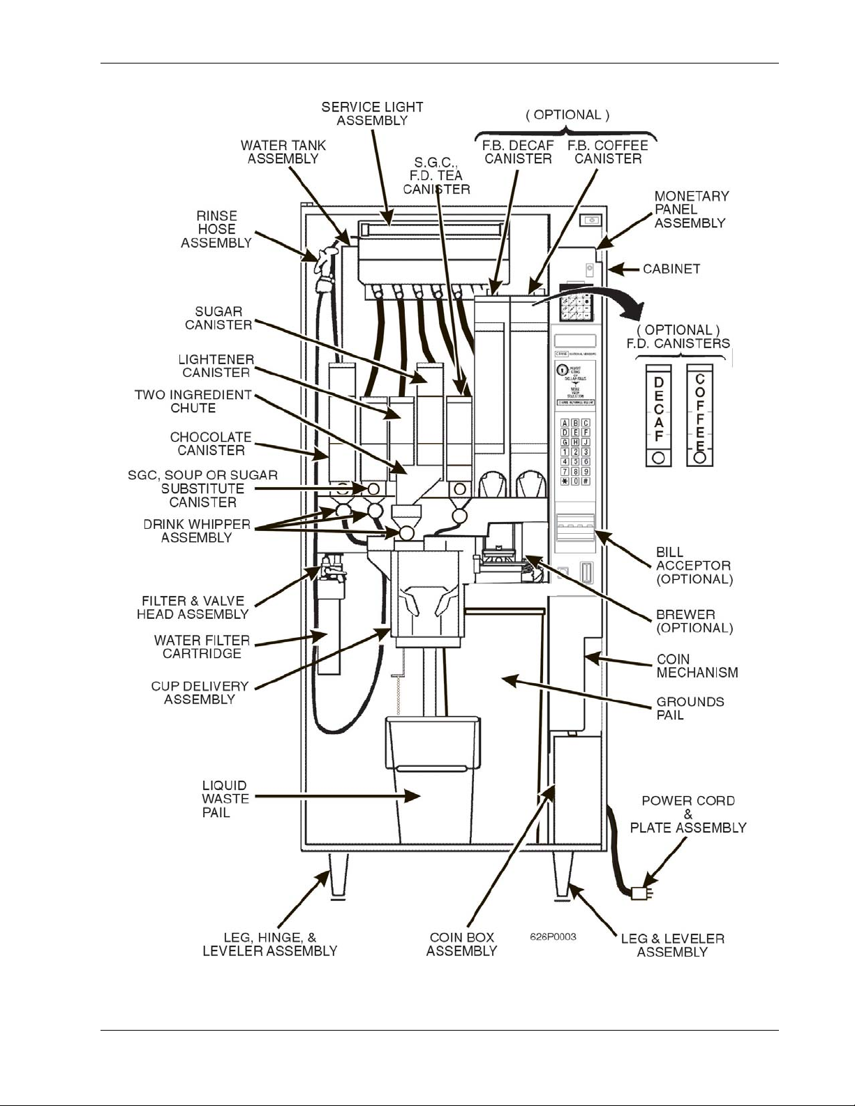
Major Parts
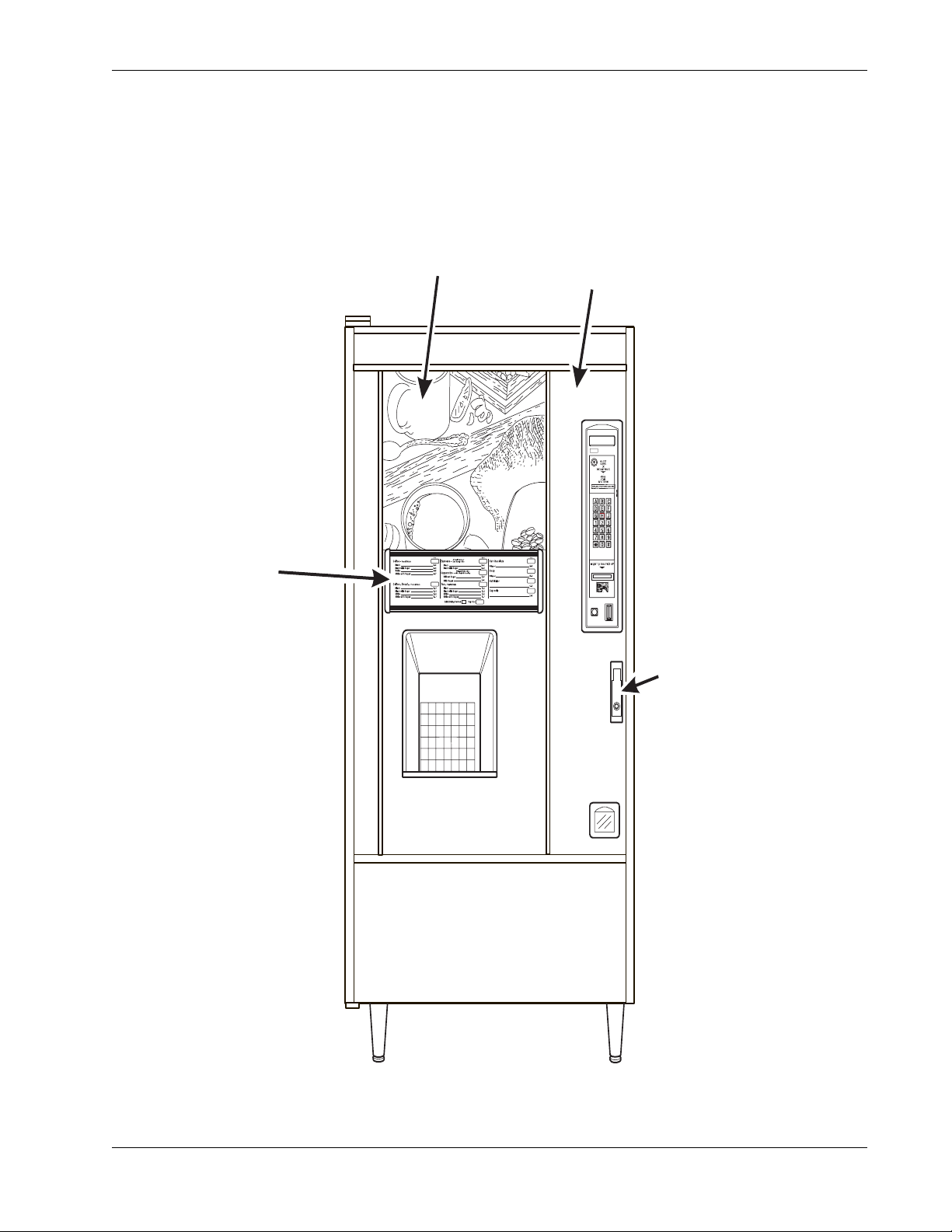
The diagrams on the following pages will acquaint you with the major parts of the HotCup
merchandiser. For more detailed information, please consult your PARTS MANUAL. If you do not
have a PARTS MANUAL, contact National Vendors Parts Department.
MENU
ASSEMBLY
PURCHASE
PHOTO
˜
EXTERIOR
DOOR
ASSEMBLY
˜
CRANE
NATIONAL VENDORS
LOC
FRONT OF MERCHANDISER
November, 2007 3 6740001
Page 10
Major Parts HotCup Operators’ Guide
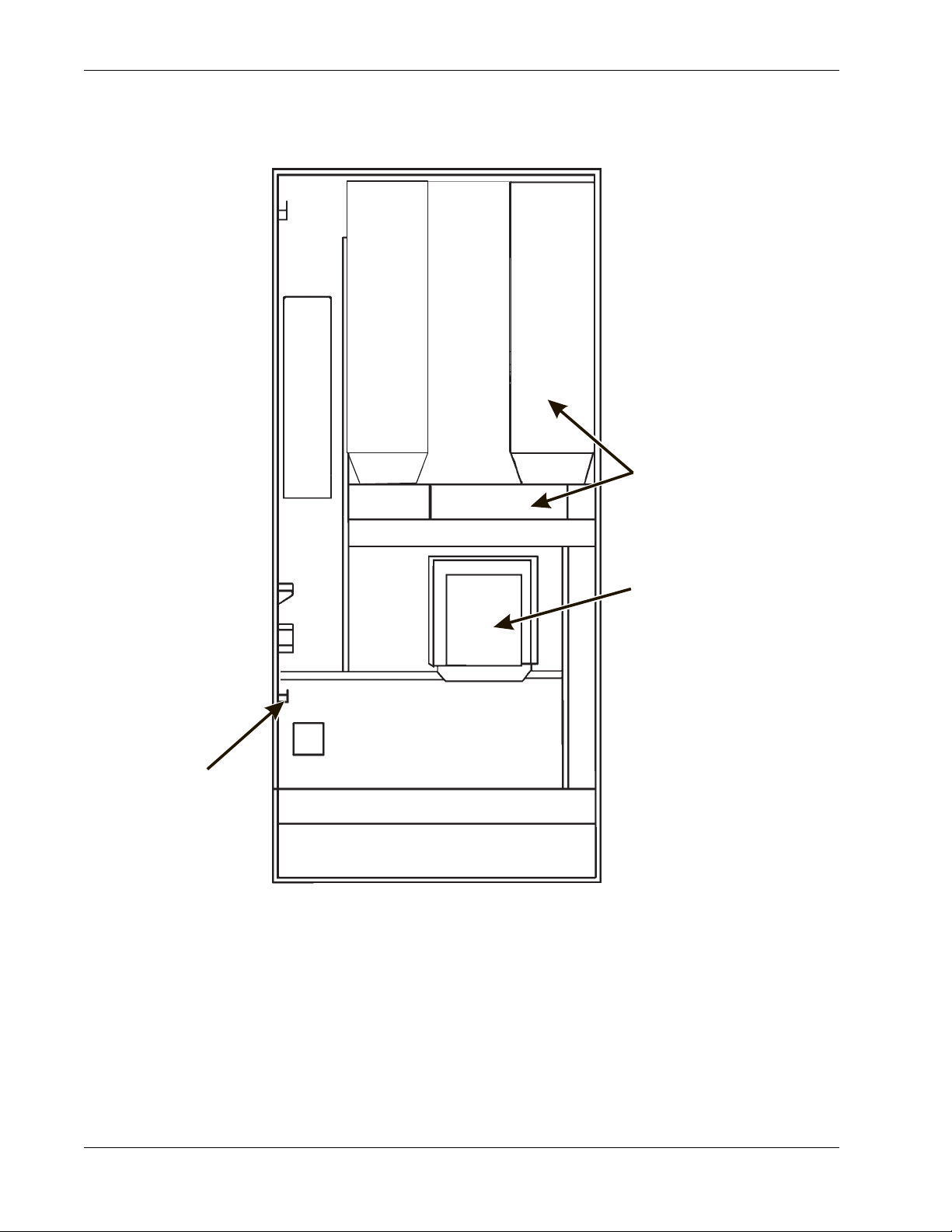
CUP MECHANISM
TURRET ASSEMBLY
AND MOTOR AND PCB
ASSEMBLY
LOCK BAR
ASSEMBLY
DELIVERY DOOR
636p0048
FRONT VIEW OF MERCHANDISER
INTERIOR VIEW OF MERCHANDISER DOOR
6740001 4 November, 2007
Page 11
HotCup Operators’ Guide Major Parts
MERCHANDISER CABINET INTERIOR
November, 2007 5 6740001
Page 12
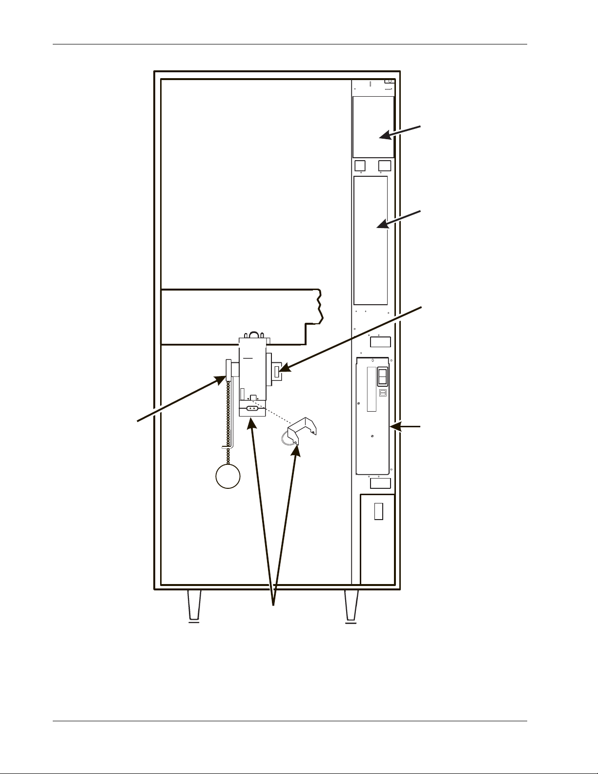
Major Parts HotCup Operators’ Guide
MAIN
˜
CONTROLLER
PCB ASSEMBLY
INTERFACE
BOARD
˜
EXHAUST
FAN
BRACKET
ASSEMBLY
OVERFLOW
SWITCH
ASSEMBLY
OPTIONAL INFRARED
CUP/MUG SENSOR
OR
Posi-Vend
I
O
POWER
PANEL
ASSEMBLY
636P0047
MERCHANDISER CABINET INTERIOR
6740001 6 November, 2007
Page 13
HotCup Operators’ Guide Controls and Indicators
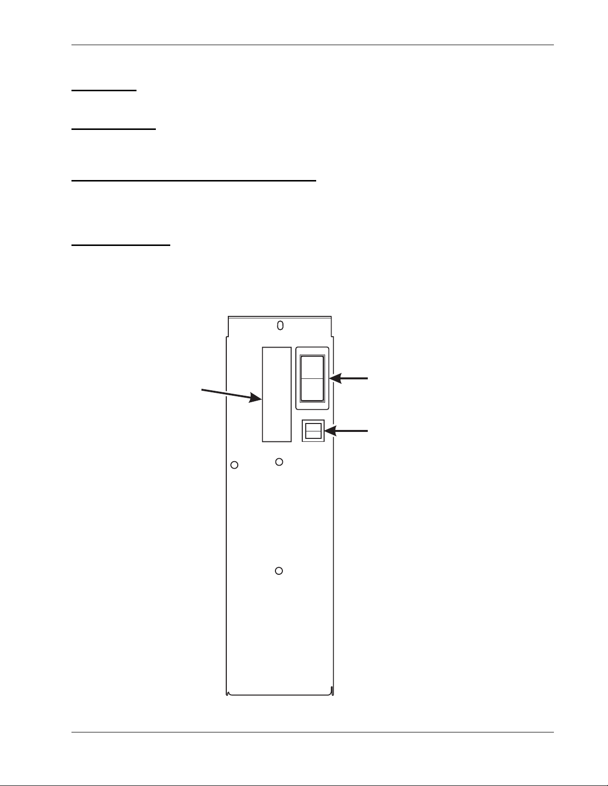
Controls and Indicators
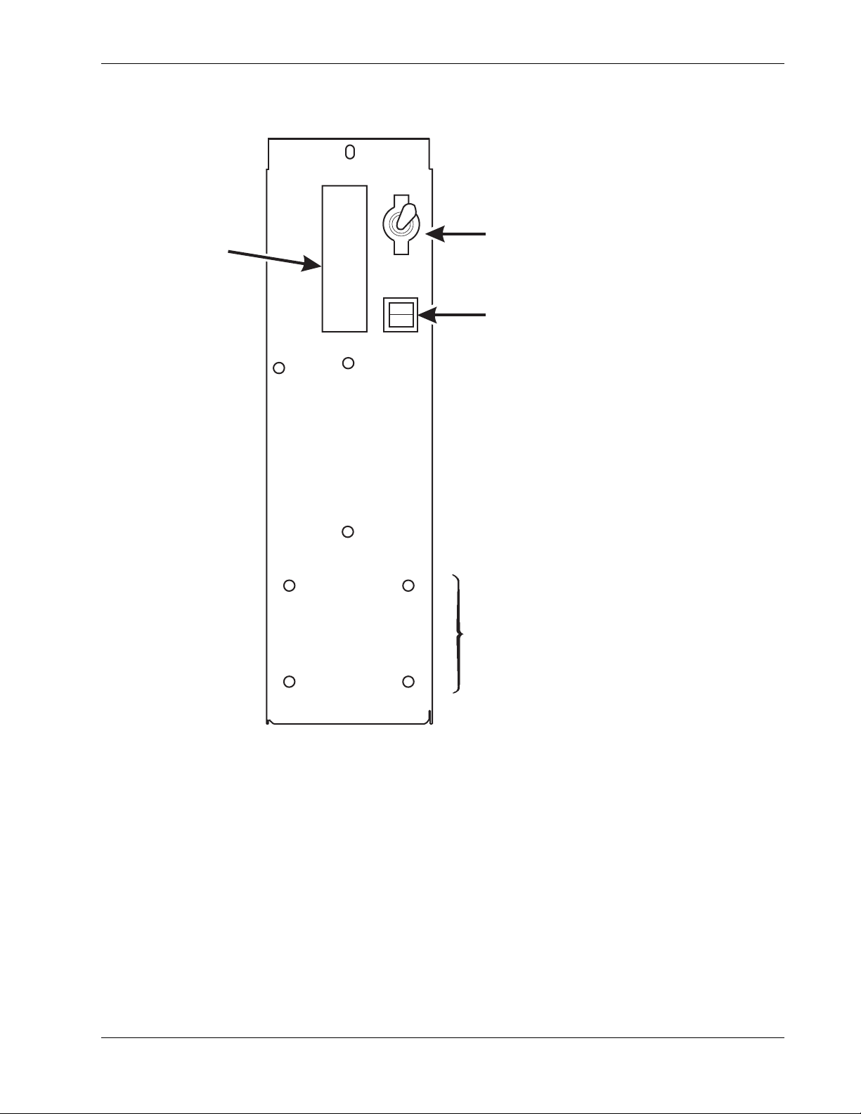
Power Panel. You may have one of three power panels, depending upon where you live. The
controls are fundamentally the same, however.
Circuit Breakers
any of the electrical components. If a circuit breaker trips and cannot be reset, consult your
troubleshooting manual.
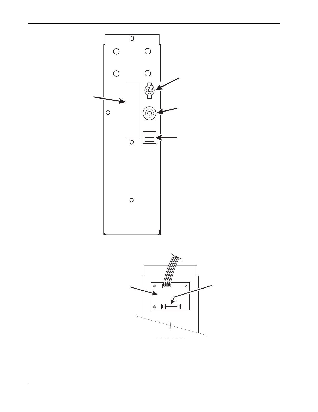
Back Side of U.S./ Canada Power Control Panel
U.S. and Canadian power control panel is a dc power supply for the coin mechanism. A fuse
protects the board circuitry in the event of a coin mechanism solenoid failure. If the coin mechanism
is not working, check this fuse. If the fuse is blown, a bad coin mechanism solenoid could be at fault.
Main Power Switch
. Circuit breakers protect the merchandiser against failures in the power supply or
. The circuit board mounted on the rear of the
. This is the main ON/OFF switch for the merchandiser.
WARNING
To protect against electrical shocks and possible damage to the
machine, turn this switch OFF when performing any maintenance
on the merchandiser.
I
MAIN
POWER
LABEL
O
SWITCH
ELECTRONICS
BREAKER
626P0005
November, 2007 7 6740001
Page 14
Controls and Indicators HotCup Operators’ Guide
1
E
P
MAIN
ON
POWER
SWITCH
LABEL
OFF
MAIN
CIRCUIT
BREAKER
LOW VOLTAGE
CIRCUIT BREAKER
POWER CONTROL PANEL (U.S./CANADA)
TOP
DC POWER
SUPPLY PCB
FOR 110V COIN MECH
˜
AGC
FUS
1 AM
BACK SIDE OF U.S./CANADA POWER CONTROL PANEL
6740001 8 November, 2007
Page 15
HotCup Operators’ Guide Controls and Indicators
L
R
ON
MAIN POWER
ABEL
OFF
SWITCH
ELECTRONICS
CIRCUIT BREAKE
MOUNTING STUDS
FOR MEXICO ONLY
POWER CONTROL PANEL
(U.K./ MEXICO)
November, 2007 9 6740001
Page 16
Controls and Indicators HotCup Operators’ Guide
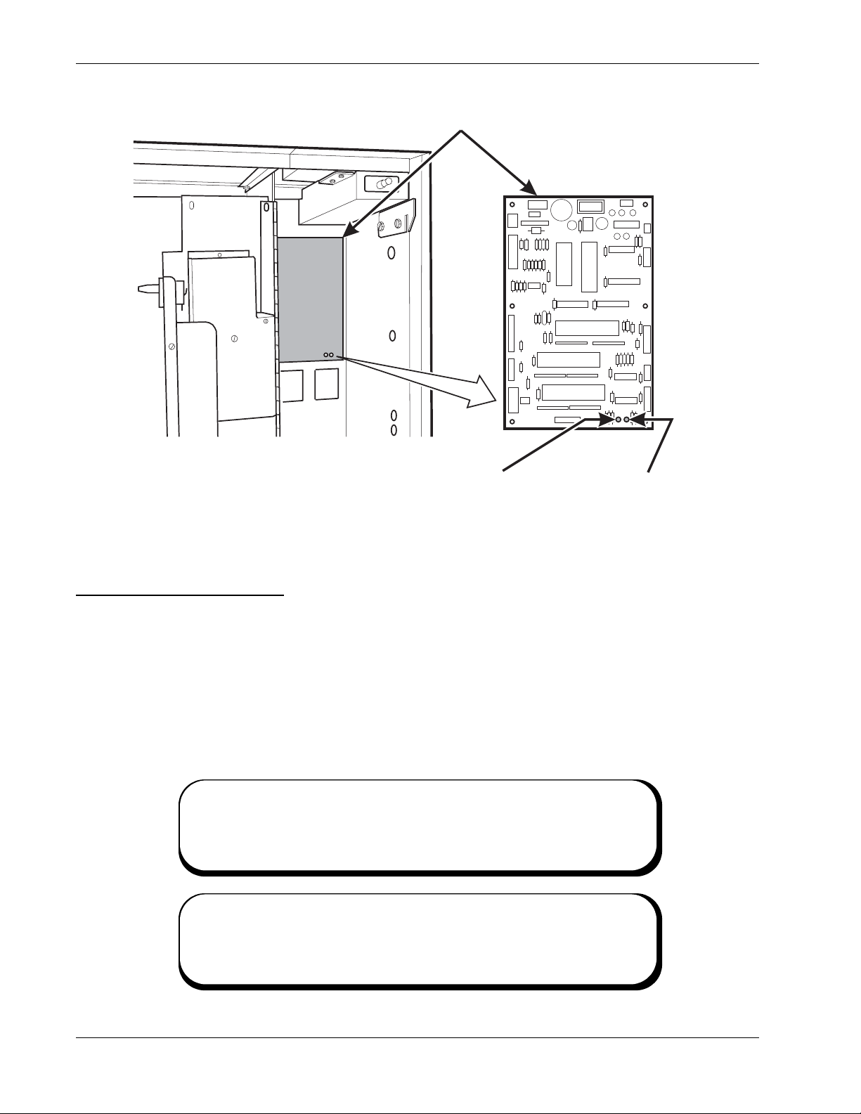
MAIN CONTROLLER
T
PCB ASSEMBLY
LED1 LED2
Main Controller PCB Display
the controller PCB.
POWER ON
(LED 1)
HEARTBEAT
(LED 2)
When lit, this red LED indicates electrical power is applied to the controller
PCB.
When flashing, this red LED indicates that the controller PCB is active, and
the software is operating.
When the merchandiser is operating normally, you should see a
steady red POWER ON indicator . The red HEARTBEAT indicator
POWER ON
(LED 1)
FLASHING
HEARTBEA
(LED 2)
MAIN CONTROLLER DISPLAY
. This display consists of two light emitting diodes (LED) mounted on
NORMAL CONDITIONS:
ERROR CONDITIONS:
If an error is present, the red HEARTBEAT indicator will flash
with an unbalanced on/off pattern (on longer than it is off). The
6740001 10 November, 2007
Page 17
HotCup Operators’ Guide Controls and Indicators
E
E
H
I
HIGH VOLTAG
INTERLOCK
SWITCH
MESSAGE
DISPLAY
FREE VEND
KEYSWITCH
(OPTIONAL)
NSTRUCTION
PLATE
LETTERS
A-H,J
NUMERALS
1-9, *,0, #
MONETARY
PANEL
COIN
RETURN
BUTTON
LOW VOLTAG
DOOR SWITC
SERVICE
KEYPAD
CABINET
SELECTION
SWITCH
BILL
ACCEPTOR
(OPTIONAL)
COIN
INSERT
MONETARY PANEL
November, 2007 11 6740001
Page 18
Controls and Indicators HotCup Operators’ Guide
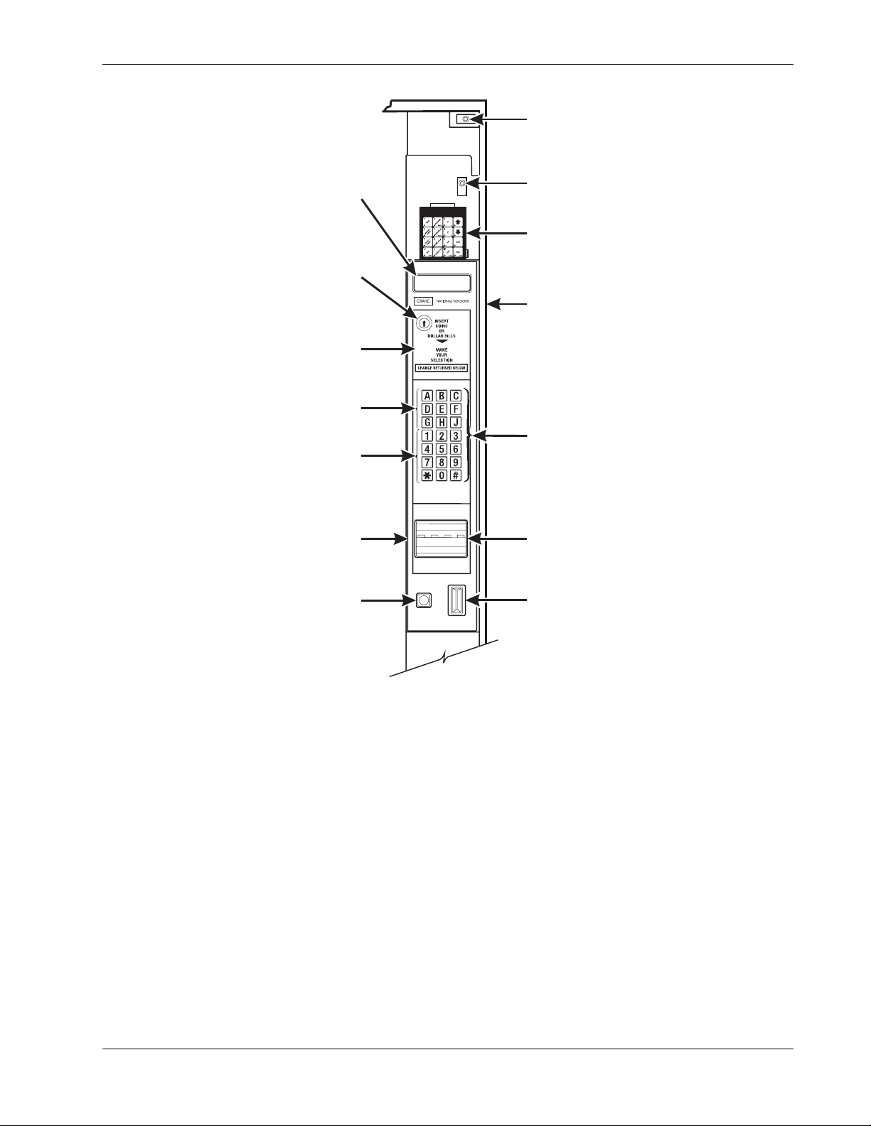
High V olt age Interlock Switch (U.S./ Canada). When the cabinet door is open, this switch turns off
the optional fan and bean light (if equipped), and turns on the service light.
High V olt age Interlock Switch (International)
all high voltage to the cabinet. Pulling the switch out restores high voltage for maintenance
purposes.
Low Voltage Door Switch
Message Display
can see messages about how much money they have put into the merchandiser. The message
display also tells customers when a selection is sold out and when vending is free, inhibited, or
discounted. The message display shows you what you are doing when you program the
merchandiser, and can show you what is wrong if there is a failure.
Free Vend Keyswitch
merchandiser to free vend without opening the door.
Selection Switch Panel
maintenance people may use this switch panel during programming and other support modes.
Coin Return Button
merchandiser prior to a vend.
Bill Acceptor (Optional)
validator, and how the machine is configured.
. This is how the merchandiser communicates with the outside world. Customers
. Informs the controller software of the main door open or closed status.
. This allows someone (other than maintenance people) to set the
. The customer uses these switches to make selections. Also,
. Pressing this button returns any coins that have been paid into the
. Accepts bills in various denominations, depending upon the type of bill
. When the cabinet door is open, this switch turns of f
Service Keypad
personnel the means to program, retrieve data from, and view diagnostic information about, the
merchandiser.
. The service keypad is located at the top of the monetary panel. It gives service
SERVICE KEYPAD
6740001 12 November, 2007
Page 19

HotCup Operators’ Guide Initial Setup
Initial Setup
I. LOCATION PREPARATION
After your machine is unpacked and placed near its permanent location, you need to make sure you
have the proper electrical and water service.
ELECTRICAL POWER REQUIREMENTS
This merchandiser needs electrical power as shown in the following table.
NOTE:
Each merchandiser should have its own electrical circuit.
POWER REQUIREMENTS
Country Volts Frequency
(Hz)
Current
(Amps)
Canada 115 60 15
France 230 50 10
Germany 230 50 10
United
Kingdom
230 50 10
United States 115 60 15
CHECK THE POWER OUTLET
This merchandiser is supplied with a service cord for the country of use and is terminated in a
grounding type plug. The wall receptacle used for this merchandiser must be properly polarized,
grounded, and of the correct voltage. Operating the merchandiser from a source of low voltage will
VOID YOUR WARRANTY. Each merchandiser should have its own electrical circuit and that circuit
should be protected with a circuit breaker or fuse conforming to local regulations.
Voltage Check - Place the leads of a voltmeter across the LINE (LIVE) and NEUTRAL
terminals of the wall receptacle. The voltmeter should indicate 110-130 volts ac for 120 volt,
60 Hz locations, or 220-240 volts ac for 230 volt, 50 Hz locations.
Polarity Check - Place the leads of a voltmeter across the LINE (LIVE) and GROUND
terminals of the wall receptacle. The voltmeter should indicate 110-130 volts ac for 120 volt,
60 Hz locations, or 220-240 volts ac for 230 volt, 50 Hz locations.
Noise Potential Check - Place the leads of a voltmeter across the NEUTRAL and GROUND
terminals of the wall receptacle. The voltmeter should indicate 0 volts ac. A measurement
greater than 1.5-2.0 volts ac could result in problems for the merchandiser's electronic
circuitry caused by electrical noise.
Any deviation from these requirements could result in unreliable performance from your
merchandiser.
November, 2007 13 6740001
Page 20

Initial Setup HotCup Operators’ Guide
WATER REQUIREMENTS
The best type of water for coffee brewing is normal hard (tap) water. If your location has chemically
softened water, you should do one of the following things:
• Have a non-softened supply line run to the merchandiser
• Contact your local water filter supplier for information and suggestions
Well water can also be used in the HotCup Machine. However, you should have it checked
for levels of carbonates and alkalies. Contact your water filter supplier if these values are
relatively high.
What is the Water Pressure at Your Location?
• It should be no less than: 10 psi ( 69.0 KPa) at 1/2 gallon/minute
• And no more than: 80 psi (522.0 KPa) at 1/2 gallon/minute
If you're not sure about the pressure and flow rate, check with your water company.
What to do With the Water Supply Line:
• Locate the supply line at the rear of your merchandiser.
• Equip the line with a shut-off valve.
Flush the water supply line before connecting it to the merchandiser. A minimum of five gallons is
usually required before connecting the merchandiser to the supply line. DO NOT flush the
merchandiser water system. If you do, you might introduce water line contaminants into the
merchandiser.
II. POSITIONING THE MERCHANDISER
You can position this merchandiser anywhere in a bank of machines. It can even be placed on the
end flush against a side wall. Be sure you leave enough room in front of the merchandiser for the
door to move freely.
BE SURE THE REAR OF THE MERCHANDISER IS AT LEAST 6"
AWAY FROM THE WALL. THIS WILL ALLOW WARM, MOIST AIR
TO BE VENTED OUT OF THE MACHINE'S INTERIOR.
WARNING:
THIS MACHINE IS ONLY RATED FOR INSTALLATION IN AN
INDOOR LOCATION.
6740001 14 November, 2007
Page 21

HotCup Operators’ Guide Initial Setup
III. CONNECTING EVERYTHING
1. Connect the Merchandiser to the Water Supply:
a. You will need the following:
•A coil of copper tubing with outside diameter of 3/8 inch (9.5 mm) or greater. The
appropriate plastic tubing may be substituted. The tubing must be long enough to reach
from the water source to your machine with enough left over to form a loop about 2 feet
(60 cm) in diameter. This will allow you to move the machine without straining the water
line.
•A 3/8 inch (9.5 mm) flare fitting.
b. Connect the merchandiser to your water supply.
2. Connect the Merchandiser to the Electrical Power Supply:
Power inside the merchandiser is controlled by the main power switch, located on the power panel.
a. Make sure the main power switch is OFF.
b. Connect the merchandiser’s power cord to your wall outlet.
November, 2007 15 6740001
Page 22
Initial Setup HotCup Operators’ Guide
SPIRIT LEVEL
LEVELER
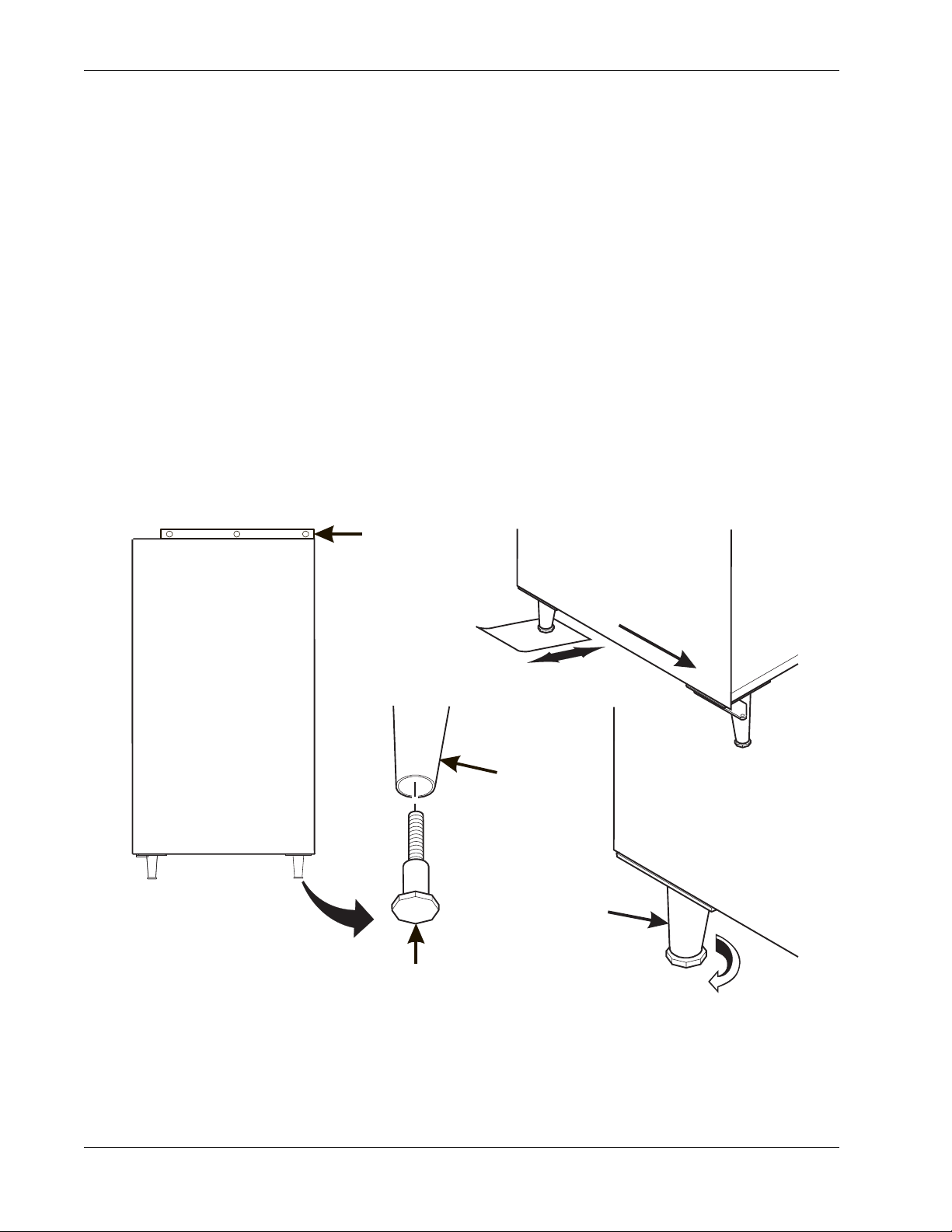
IV. FINAL MECHANICAL PREPARATION
1. Level the Merchandiser:
a. Place a spirit level on the top front edge of the cabinet with the door fully closed. Adjust the
front legs only until the cabinet is reasonably level.
b. Hold the door open about 4 inches.
WARNING:
HAVE AN ASSISTANT HOLD THE MERCHANDISER WHILE YOU
ADJUST THE LEG LEVELERS.
c. Adjust the back legs so that the back leg leveler on the hinge side is off the floor just enough
so a piece of paper can slide under it with only a bit of resistance.
d. For proper weight distribution on all four legs, raise the back leg on the hinge side by
unscrewing the leveler 1½ turns.
NOTE
You may need to use pliers or channel locks to loosen the leg
levelers.
LEG
FRONT
LEG
LEFT REAR
LEG
1-1/2 TURNS
6740001 16 November, 2007
Page 23
HotCup Operators’ Guide Initial Setup
B
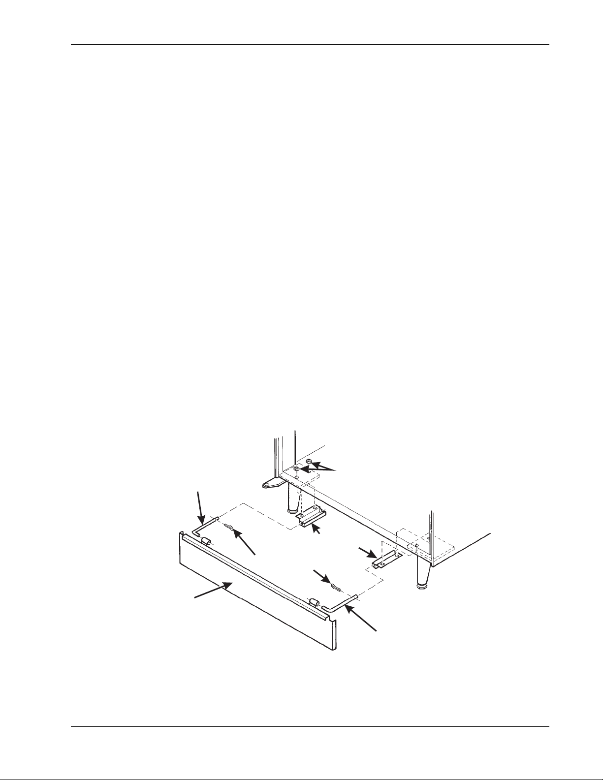
2. Mount the Base Plate:
WARNING
DO NOT MOVE THE CABINET WHILE HEX HEAD SCREWS AND/
OR CARRIAGE BOL TS ARE LOOSENED. THE CABINET WOULD
BECOME UNSTABLE AND LIKELY TO TIP AND CAUSE INJURY.
a. Remove the pail(s) from the inside of the merchandiser.
b. Remove the floor liner from the inside of the merchandiser.
c. Remove the two caps as shown.
d. Loosen the left leg assembly carriage bolts and nuts to allow mounting a base plate bracket.
e. Secure one of the base plate brackets to the leg assembly using the two carriage bolts.
Tighten the carriage bolts and nuts.
f. Loosen the right leg assembly hex head screws to allow mounting the other base plate
bracket.
g. Secure the other base plate bracket to the right leg assembly using the two hex head screws.
Tighten the hex head screws.
h. Insert the short arms of the slides into the hinged t abs of the base plate. Position the slide so
the notch near the short arm is on the bottom side.
i. Insert the long arms of the slides into the base plate brackets.
j. Insert and secure a cotter pin through the hole in the back of each of the slides.
k. Push the base plate toward the merchandiser cabinet. The front tabs of the base plate
brackets should seat in the notches in the long arms of the slides.
l. Replace the caps, liner, and pail(s) removed previously.
CAPS
SLIDE - L.H.
BASE PLATE BRACKET
COTTER PIN
ASE PLATE
ASSEMBLY
SLIDE - R.H.
November, 2007 17 6740001
Page 24
Initial Setup HotCup Operators’ Guide
1
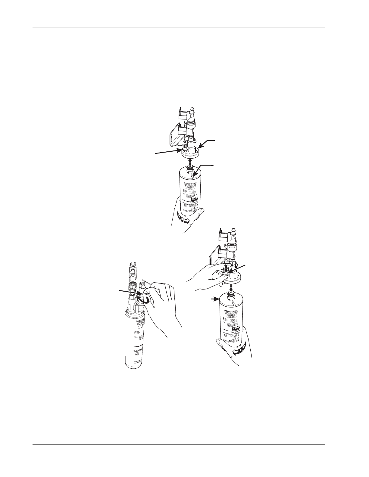
3. Install the Water Filter Cartridge:
IF YOUR MERCHANDISER HAS THE WATER FILTER OPTION, IT
CANNOT BE OPERATED WITHOUT A PROPERLY INSTALLED
WATER FILTER CARTRIDGE. If you do not have the water filter
option, continue with "Fill the Tank".
CUNO BRAND ...
CUNO FILTER
FILTER
LOCKING
TAB
TO INSTALL
THE FILTER:
1. INSERT NEW FILTER,
ROTATE COUNTERCLOCKWISE UNTIL
FILTER LOCKING TAB
SNAPS INTO GROOVE
AS SHOWN.
HEAD ASSEMBLY
GROOVE
TO REMOVE FILTER:
. CLOSE THE WATER SHUT
-OFF VALVE BY TURNING
THE KNOB TO THE
HORIZONTAL POSITION
AS SHOWN.
WATER
SHUT-OFF
KNOB
2. LIFT THE FILTER
LOCKING TAB,
ROTATE FILTER
CLOCKWISE AND
PULL DOWN AS
SHOWN.
CUNO
FILTER
FILTER
LOCKING
TAB
Note:
Check the water filter installation record. There is a pla ce to write
the vend number on the cartridge. The cartridge is effective for a
maximum of 64,000 7 oz. vends, 56,000 8 oz. vends, 50,000 9 oz.
vends, or 37,000 12 oz. vends. Local conditions may require
more frequent replacement.
6740001 18 November, 2007
Page 25
HotCup Operators’ Guide Initial Setup
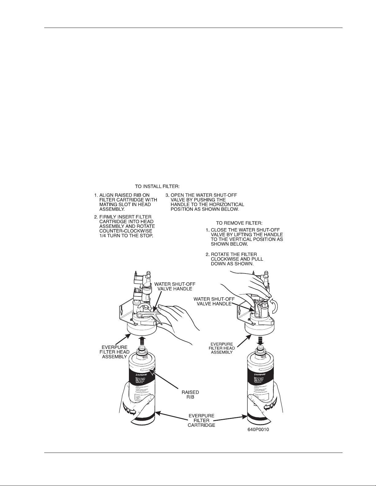
EVERPURE BRAND...
NOTE
Check the water filter installation record. There is a pla ce to write
the vend number on the cartridge. The cartridge is effective for a
maximum of 26,000 7 oz. vends, 22,000 8 oz. vends, 20,000 9 oz.
vends, or 15,000 12 oz. vends. Local conditions may require
more frequent replacement.
a. GPL recommends that you do the following procedure the first time you fill the tank in your
EuroDrink merchandiser:
b. Remove the small inner "O" ring from the filter cartridge.
c. Install the filter cartridge.
d. Turn on the water at its source, and perform the tank filling procedure.
e. Turn off the water at its source, remove the filter cartridge, and replace the "O" ring.
f. Install the filter cartridge.
November, 2007 19 6740001
Page 26
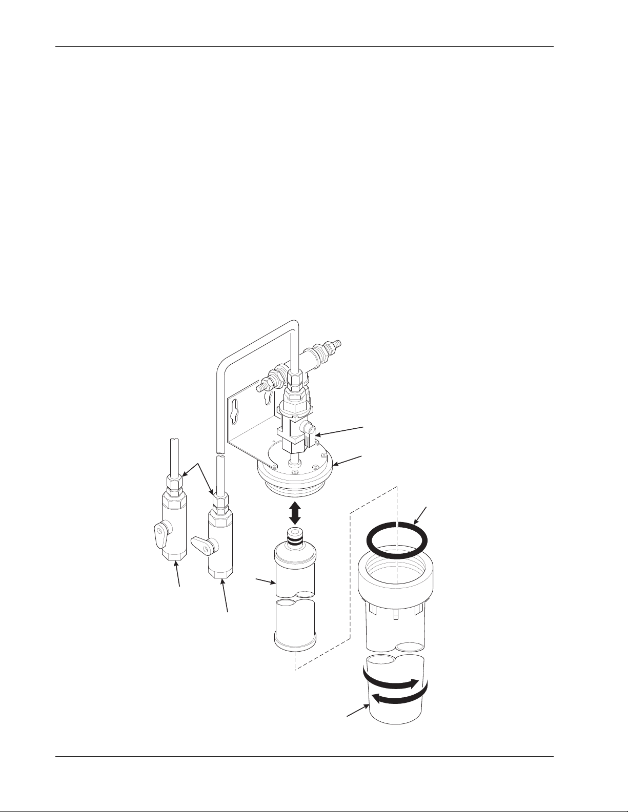
Initial Setup HotCup Operators’ Guide
E
HYDROLIFE BRAND
INSTALLATION:
a. Place the filter inside the canister. Be sure the o-ring is seated in the canister just below the
threads.
b. Screw the canister and filter assembly onto the filter head until it comes to a stop.
c. Open the water valve on the inlet line by rotating the handle to the vertical position as shown.
REMOVAL:
a. Close the valve on the inlet line by rotating the handle into the horizontal position as shown.
b. Relieve water pressure by performing two or three water throws (See “Programming The
HotCup” on page 34).
c. Unscrew the filter and canister assembly from the filter head. Remove the filter from the
canister.
OPEN
POSITION
VALVE
CLOSED
POSITION
FILTER
CANISTER
INSTALL
OPEN
POSITION
HYDROLIFE
FILTER HEAD
O-RING
REMOV
6740001 20 November, 2007
Page 27
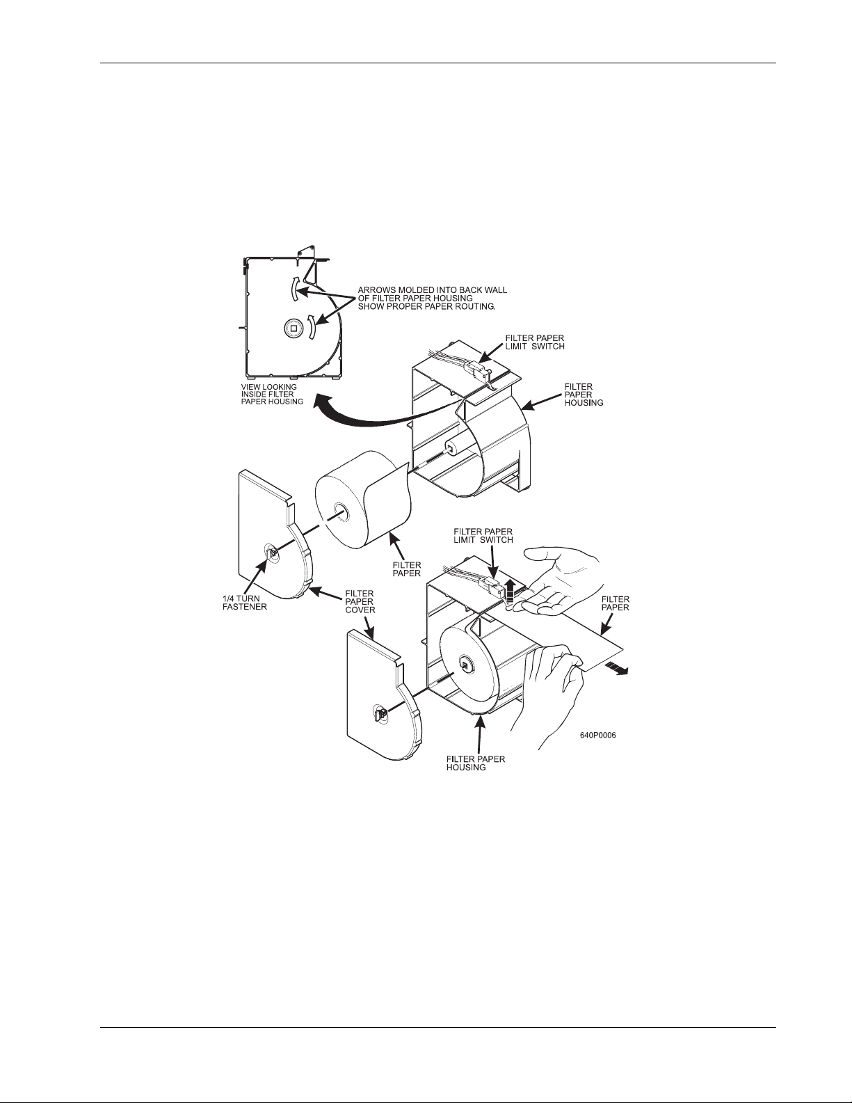
HotCup Operators’ Guide Initial Setup
4. Load the Optional Filter Paper:
1
a. Turn the fastener
b. Insert filter paper in the filter paper housing as shown.
c. Feed the paper out of the housing as shown by the arrows molded into the back wall of the filter paper
housing
/4 turn counterclockwise and remove the filter paper cover.
d. Lift up the limit switch and feed the paper past it as shown. Release the limit switch.
e. Replace the cover.
.
f. Refer to routing label on filter paper cover. Feed paper under paper guide shaft and over rounded edge
of stainless steel brackets as shown.
g. Lift and rotate the idler roller assembly up.
h. Route the paper under the brewer cylinder and the idler rollers.
i. Release the idler roller assembly, capturing the filter paper.
November, 2007 21 6740001
Page 28
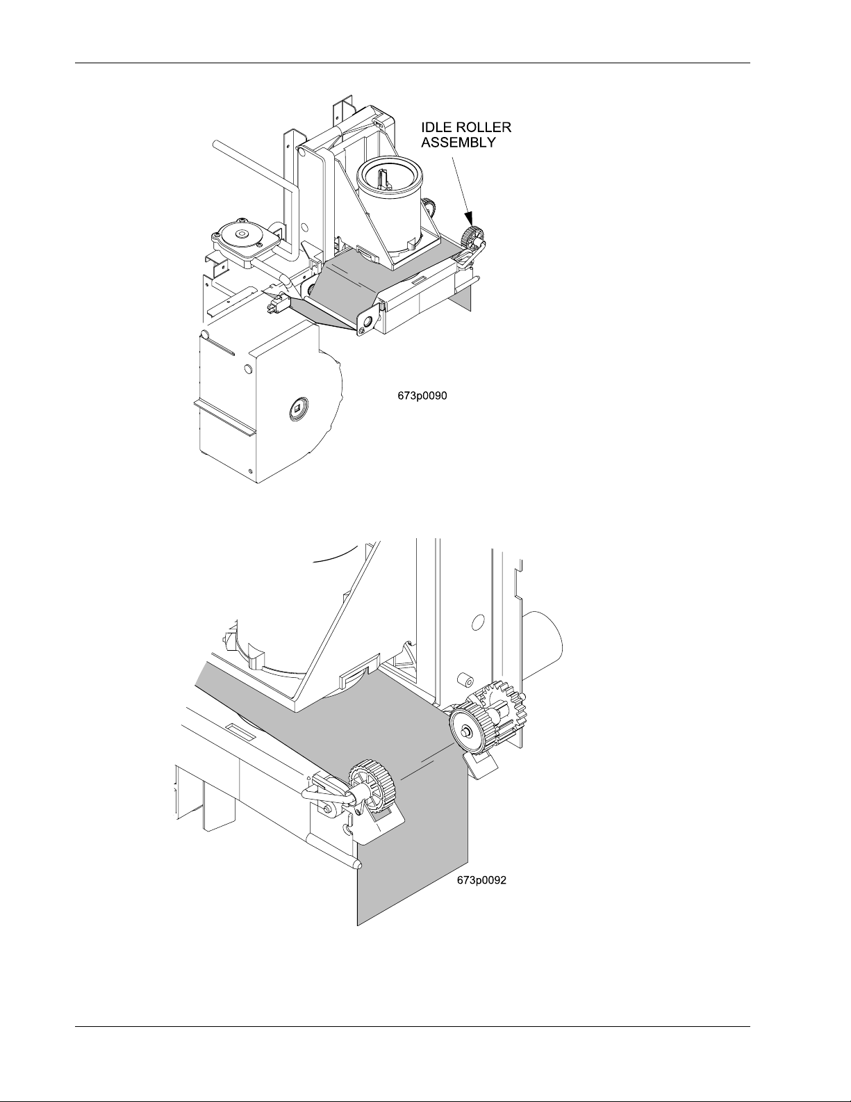
Initial Setup HotCup Operators’ Guide
j. Route the paper into the grounds bucket
k. Place the main power switch in the ON position.
6740001 22 November, 2007
Page 29
HotCup Operators’ Guide Initial Setup
l. Test the brewer to be sure the paper feeds properly: On the service keypad, press ,
then press until the display shows BREW TEST.
i. Press to test each brewer position:
WARNING
Keep away from the brewer mechanism while it is operating.
Coming into contact with moving parts could injure you.
BREW 'R BREW The brewer is in the clamp position.
BREW 'R HOMe The brewer is in the open position.
ii. Make sure the filter paper feeds properly without jamming.
iii. Replace the cup station and grounds bucket.
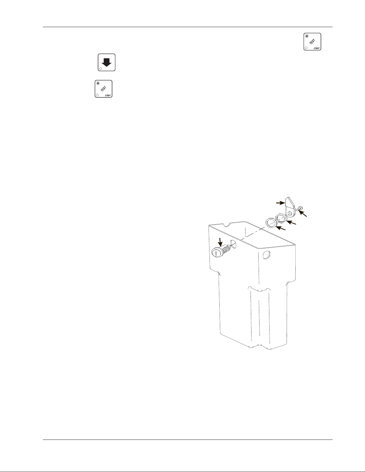
5. Install the Optional Coin Box Lock
a. Install the lock cylinder, washer , and nut in the
order shown.
b. Tighten the nut.
c. Install the lock bar as shown, and secure with
the screw.
6. Set Up and Load the Coin Mechanism
Standard Coin Mechanism
Setting the Quarter Switch. If your coin
mechanism is not a MARS TRC 6000, skip this
procedure and begin LOADING THE COIN
MECHANISM.
a. Flip down the front of the coin mechanism as
shown, and set the quarter switch.
Load the Coin Mechanism.
LOCK
CYLINDER
LOCK BAR
SCREW
NUT
WASHER
626P0011
a. Open the cabinet door and the monetary door.
b. Insert coins into their respective tubes until each tube has been filled.
c. Inspect the tubes for shingled coins and correct if necessary.
November, 2007 23 6740001
Page 30
Initial Setup HotCup Operators’ Guide
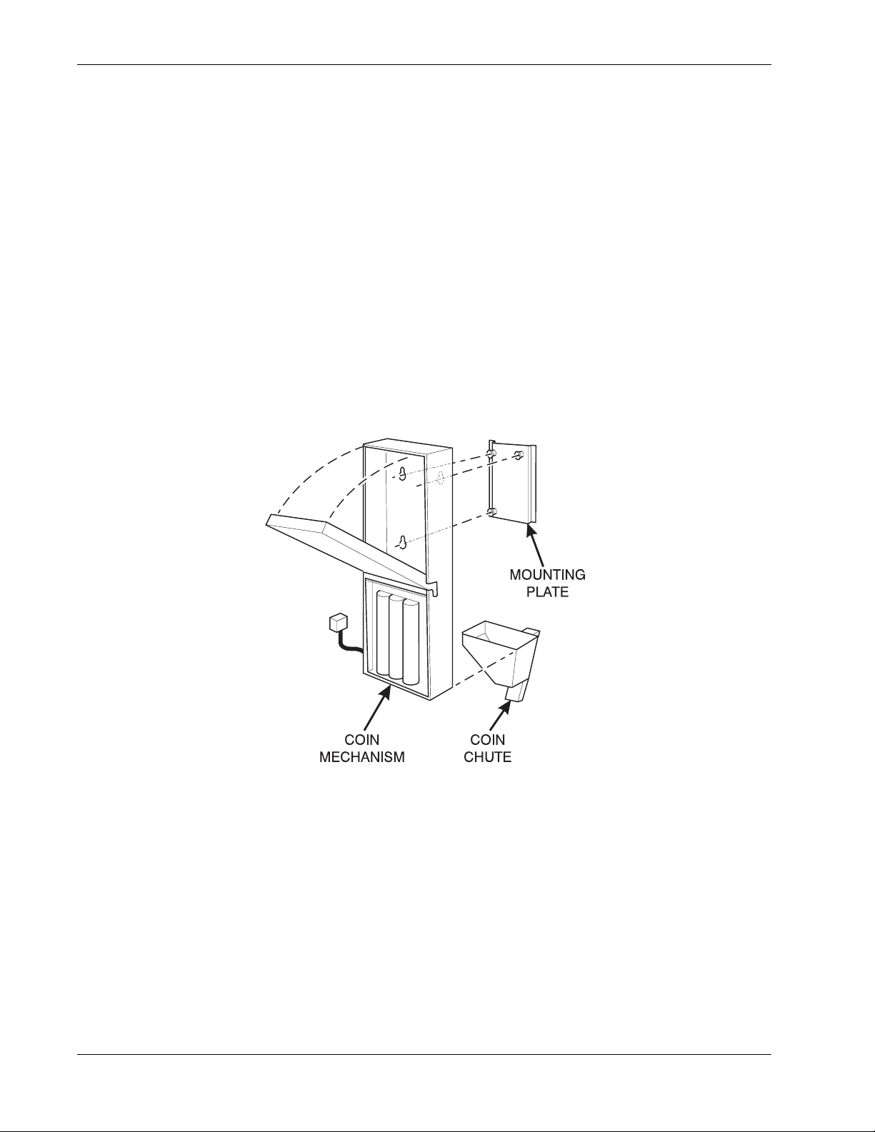
MDB Coin Mechanism
Install the coin mechanism as follows:
WARNING
Make sure the main power switch is turned OFF before
you work on the merchandiser. Failure to do so
could result in death or injury.
a. Turn OFF the main power switch. Refer to the instruction s provided with the coin mechanism
and remove the coin validator assembly.
b. Loosen the coin mechanism mounting screws on the merchandiser so they stand off about 1/
8" (0.3 cm).
c. Position the coin mechanism so the three keyed holes fit over the mounting screws. Pull
down on the coin mechanism to seat the screws in the keyways.
d. Tighten the mounting screws and reinstall the coin validator assembly.
6740001 24 November, 2007
Page 31
HotCup Operators’ Guide Initial Setup
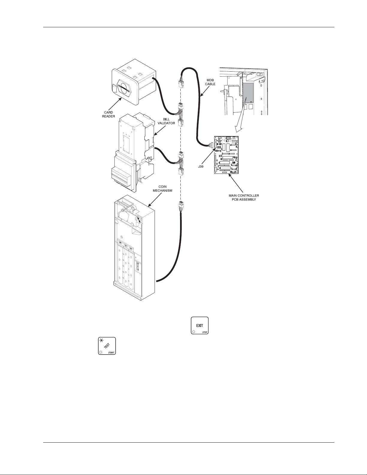
e. The following figure shows a coin mechanism, bill validator, and card reader connected to
one another via an MDB. Some monetary configurations may not include all of these
devices. Connect your coin mechanism as shown:
f. Turn ON the main power switch. Select MDB mech in the SELECT COIN MECHANISM AND
OPTIONS procedure on page 2-11. Press until the standby message is displayed,
then press . Insert enough coins through the coin slot into the coin tubes to more than
cover the empty sensor. Insert coins one at a time and ensure they lay flat in the tubes. The
amount of coins you insert is internally recorded.
g. Payout about 6 coins to ensure proper loading.
h. Finish inserting coins through the coin slot to fill all the tubes with coins.
i. Visually check the coin tubes to make sure coins are not shingled.
November, 2007 25 6740001
Page 32
Initial Setup HotCup Operators’ Guide
7. Fill the Tank:
a. Make sure the main power switch is ON.
b. Turn on the water at its source.
c. On the service keypad, press , then press until the display shows TANK.FILL.
d. Press . You should hear water running into the tank, and the display will show
FILLING. The water will run until either the tank is full or 12 minutes go by, whichever
happens first.
NOTE
The inlet water valve only stays open for 12 minutes at a time.
This is a safety feature to prevent water from running into a leaky
system and making a mess. It is possible for your tank to take
longer than 12 minutes to fill if your location has low water
pressure. T o be on the safe side, check for leaks if the water run s
a long time. If you find none, everything is normal; you just have
low water pressure.
e. When you hear the water stop running, repeat steps 3 and 4. Under normal circumstances,
nothing will happen. If water starts running and the display shows FILLING again, your
pressure is low and it is just taking a long time to fill the tank. Repeat this step if necessary to
be sure your water tank is full.
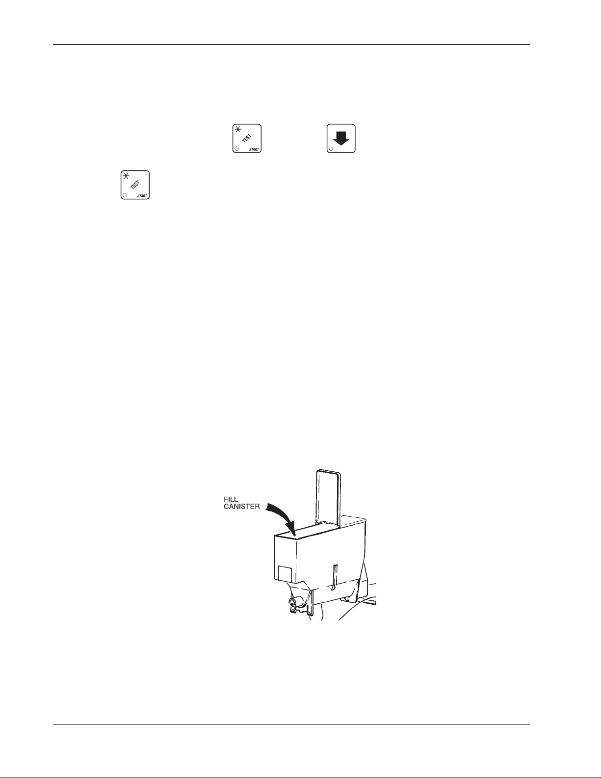
8. Fill the Canisters:
Open the lid as shown, and carefully pour the appropriate product into the canister. Repeat for
all canisters in the machine.
6740001 26 November, 2007
Page 33

HotCup Operators’ Guide Initial Setup
9. Load Cups:
CAUTION
Use only cups which have been designed for use in a hot
beverage vending machine.
a. Support the cup mechanism in the upright position.
b. Push the latch forward to release the cup mechanism. Continue to support the cup
mechanism while you lower it into the loading position.
c. Remove the turret cover.
OBSERVE PROPER HYGIENE - DO NOT TOUCH THE CUPS!
d. Open the bottom of the wrapper on a stack of cups.
e. Insert the wrapped cups into the turret and pull the wrapper out.
DO NOT FILL CUPS ABOVE THE LEVEL MARKED ON THE
OUTSIDE OF THE CUP TURRETS OR ABOVE THE “FILL LINE”
LABEL INSIDE EACH TURRET, OR MOTOR JAMS WILL OCCUR.
USE ONL Y THE SAME SIZE AND BRAND OF HOT DRINK CUPS IN
EACH TURRET; DO NOT INTERMIX!
f. Replace the turret cover afrter the turrets have been loaded.
g. Be sure the cup mechanism is locked into the upright position.
10. Cup Size(s):
a. Make sure the cup sizes you select agree with the cups you have actually loaded during
setup.
b. Press , the display shows X OZ Y. “X” is the currently selected drink size for the cups
in turret 2 (normally large cups), “Y” is the currently selected drink size for the cups in turret 1.
(Normally regular cups).
c. Press to change the #1 cup ring size; press to change the #2 cup ring size.
d. Any changes made to the cup sizes must be “locked in”. There are two ways to do this:
i. If you are keeping some cup sizes the same, or putting the cups in different cup rings,
press and hold . The display momentarily shows CLEARING, two beeps sound,
then shows FINISHED. This will reassign the old throw times to the new cup ring, if
possible.
ii. If you are loading all different size cups, or want to load all new default times, press and
hold . The display momentarily shows CLEARING, two beeps sound, then shows
FINISHED. This will reload the factory default times you have established.
e. CONTINUE.
November, 2007 27 6740001
Page 34

Initial Setup HotCup Operators’ Guide
11. Test the Machine:
Your HotCup merchandiser is now ready to vend coffee, just as soon as the water in the tank
reaches its operating temperature. Press , and a reading of the tank temperature is
displayed. When the display shows 94° C (202° F), it is ready for vending.
a. Close the door, make a selection, and enjoy your cup of coffee!
b. You will now need to do the following before your machine is ready to start earning money:
•Set prices
•Set up the menu
•Establish time of day vending periods (if desired)
•Customize the drink recipes (if desired)
•Set up custom messages (if desired)
Refer to the Programming section for details on these and other procedures.
6740001 28 November, 2007
Page 35

HotCup Operators’ Guide Initial Setup
12. PosiVend:™
PosiVend ™ensures that a cup is always available in the cup st ation before any money is collected or
product delivered. The sensing system is a beam of infra-red light across the cup station which is
broken by the cup when it falls into position.
The PosiVend™ software monitors the cup station sensor during the time the cup ring is cycled and
for three seconds afterward. If a cup is not detected, the soft-ware will first determine if a second cup
ring with the same size cups exists and will then try to drop a cup from the second ring. If the second
ring also fails to drop a cup or is not usable, the software will repeat the attempt from the first cup ring
to attempt to clear any jams in the cup delivery area. Each ring will be tried up to two times. If a cup
is still not detected by the infrared sensor then several things happen:
• Any ring that failed twice in a row is placed temporarily out-of-service for a length of time that
is determined by the user,
• The customer’s credit is either restored for another vend attempt or is returned automatically,
• Three beeps are sounded and the message SELECT ANOTHER SIZE is flashed if another
size cup ring is available, or the message INSERT MUG is flashed in the event that no other
cups are available. The customer may always get his money back by pressing the coin
return button.
Insert mug is the default message.
You may customize this message if desired.
Special rules exist to protect both the customer and the operator from loss. First and foremost, the
customer is protected because no drink is spoiled nor money lost because a cup fails to fall to the
cup station. The customer is given every chance to get his original choice of cup size by trying at
least twice per ring to eject a cup. If two rings are available with the same cup size, the system will
alternately try to vend a cup from each ring until the cup is delivered or both rings are placed out-ofservice.
The operator is protected by the anti-jackpot program of the system. It is con-ceivable that a
customer could prevent cups from reaching the sensing area of the cup station in order to steal the
cups and then get his or her money back for the vend. Under the PosiVend™ Anti-Jackpot system,
the operator can lose no more than two cups in a row per ring. Then that ring is temporarily placed
out-of-ser-vice both to protect the customer and to discourage theft. The amount of time that the cup
ring is out-of-service is programmable from 0 to 99 minutes. After the time has elapsed, the cup ring
will return to service but the count of the two failures is kept. If the previous problem was theft, then
the next vend attempt from that ring will be successful and the count of the two previous failures will
be erased. If the problem is an actual system failure, then the third failure will permanently place that
cup ring out of service until a service technician visits the machine.
Alternate cup vends and mug vends still work as before. If a cup ring is out of service due to
PosiVend™ the alternate vend will only be from a selected large cup to a small cup at the small cup
price. An induced PosiVend™ failure cannot cause an alternate vend from a selected small cup to a
large cup at the small cup price. This protects the operator from customers trying to get large cup
drinks at a small cup price. (PosiVend™ will not automatically switch to a different cup size in midvend because it cannot be ensured that correct change will be returned for the new price.)
PosiVend™ can be turned off if desired, (See “Turn PosiVend™ On or Off” on page 64).
November, 2007 29 6740001
Page 36
Initial Setup HotCup Operators’ Guide
R
WATER
V. ADJUSTMENTS AND MINOR MAINTENANCE
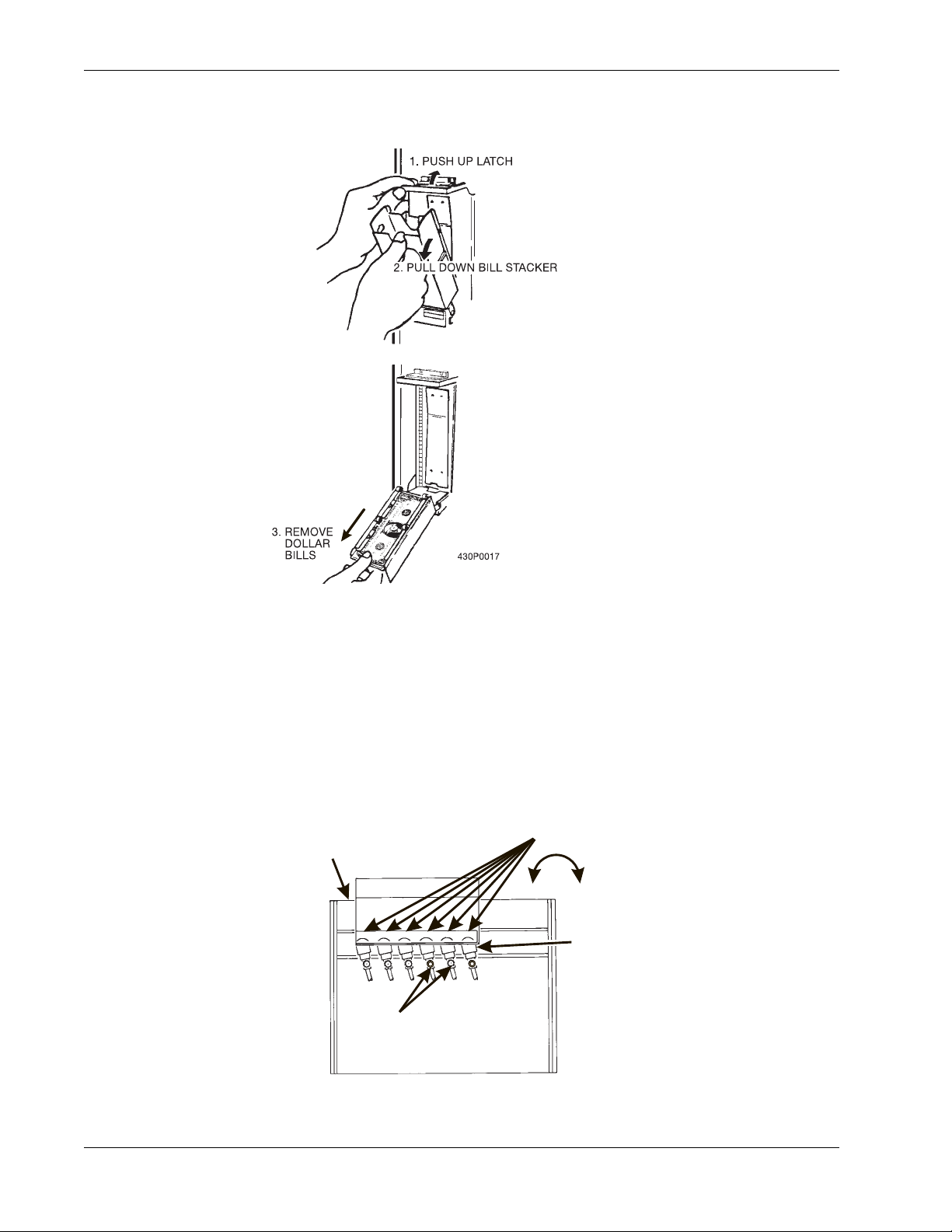
1. Empty the Bill Stacker
2. Adjust the Water Valves
Water valves do not usually require adjustment, but in some cases adequate water volume cannot
be achieved by the throw time setting alone (See “Programming The HotCup” on page 34). If
absolutely necessary, adjust the valves in conjunction with setting the factory default timers during
the Product Configuration programming mode.
a. Using a slotted screwdriver, turn the adjustment screw clockwise to decrease the water flow
rate.
b. Turn the adjustment screw counterclockwise to increase the water flow rate.
WATER
TANK
WATER VALVE
ADJUSTMENT
SCREW
123456
6
+
-
WATE
VALVE
6740001 30 November, 2007
Page 37
HotCup Operators’ Guide Initial Setup
FILL
CANISTER
CANISTER
SHELF
PINS ON MOTOR
SHAFT MUST ENGAGE
SLOTS
IN CANISTER
COUPLER
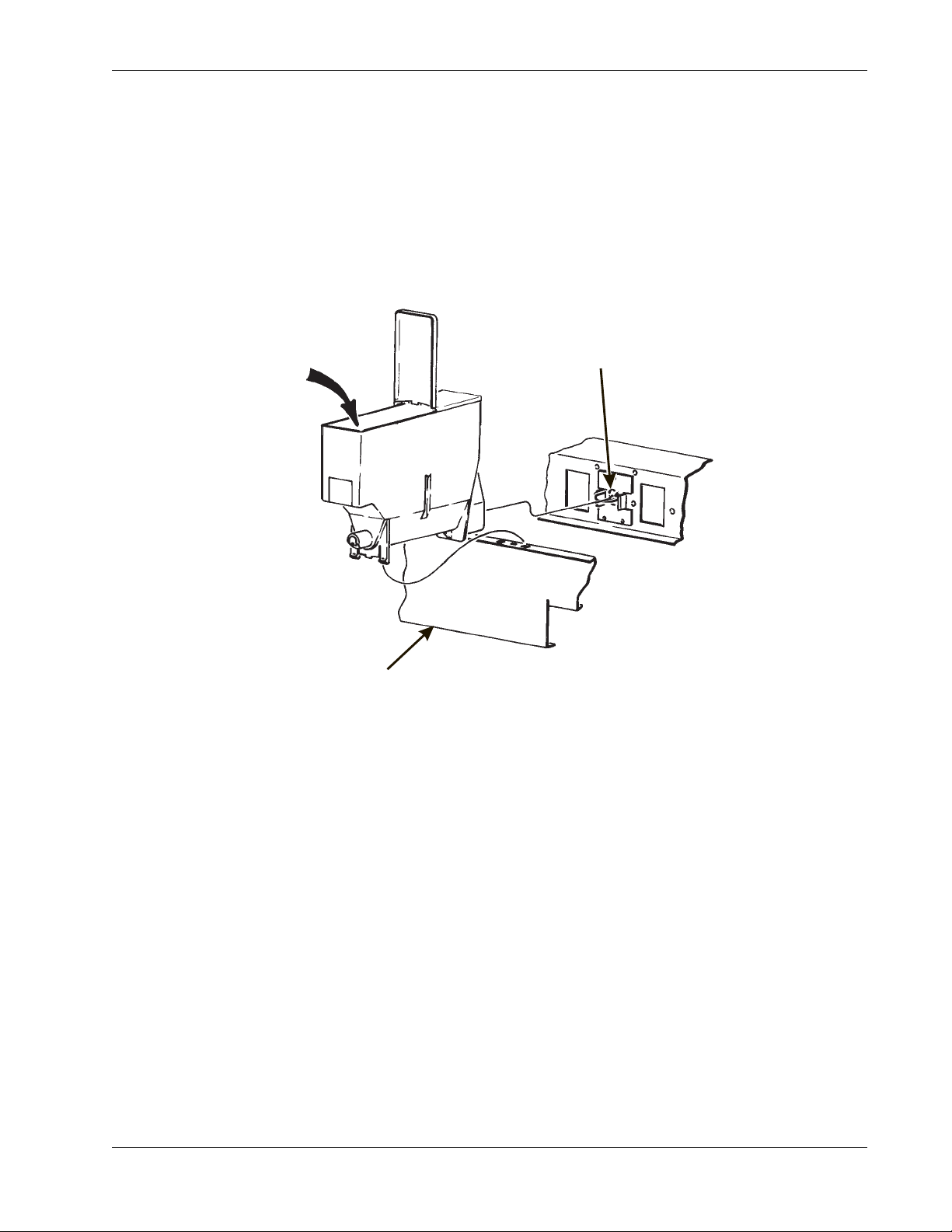
3. Install Canisters.
a. Place the canister in position as shown.
b. Engage the pins on the motor shaft with the slots in the canister coupler.
c. Fit tabs on canister into the slots on the canister shelf.
d. To ensure canister is correctly engaged with the rear mounting bracket, gently push down on
the front edge of the canister lid.
PINS ON MOTOR
SHAFT MUST ENGAGE
SLOTS IN CANISTER
FILL
CANISTER
COUPLER
CANISTER
SHELF
626P0017
November, 2007 31 6740001
Page 38
Initial Setup HotCup Operators’ Guide
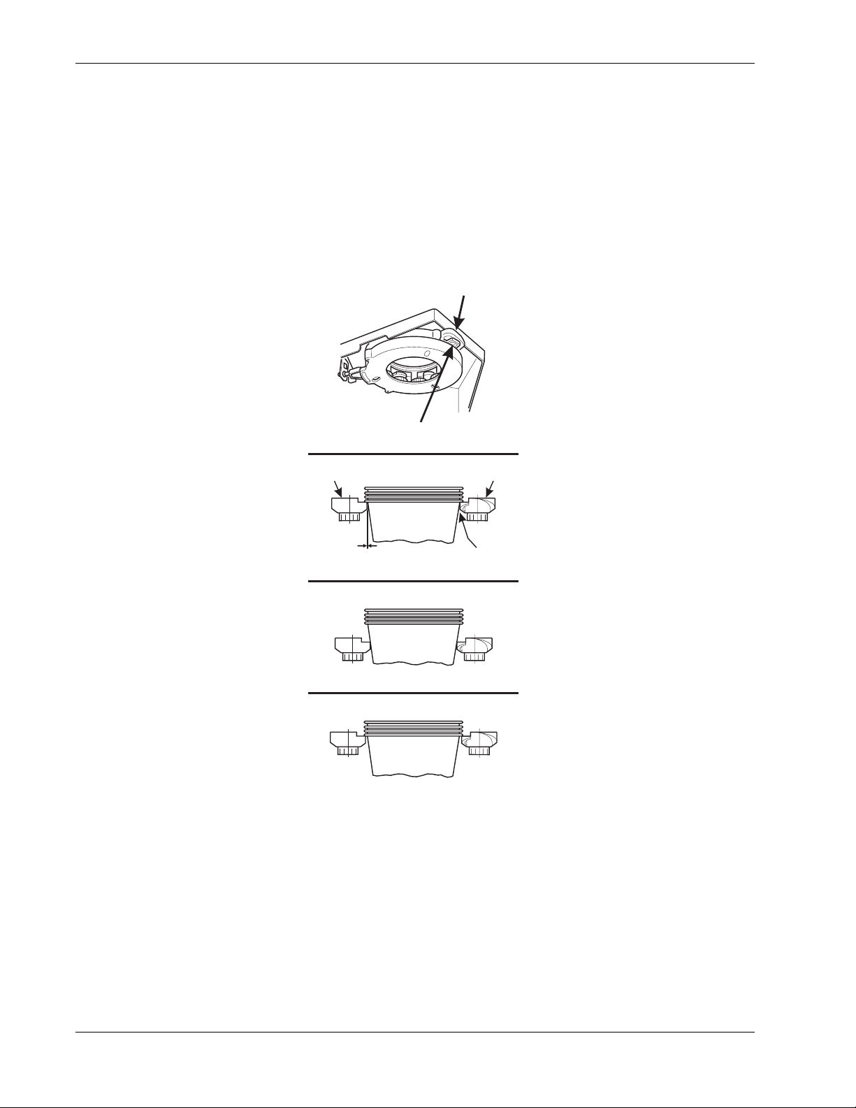
4. Adjust the Cup Mechanism.
a. Place seven cups in the cup ring.
b. Observe the clearance as shown in view B.
c. If necessary adjust by first loosening the adjustment arm screw (view A).
d. Move adjustment arm until correct clearance is achieved.
e. Hold adjustment arm in place and tighten adjustment arm screw.
ADJUSTMENT
ARM
View A
LOOSEN SCREW
MOVE ARM
CUP
CAM
CUP
CAM
View B
CORRECT
ADJUSTMENT
This clearance is just
large enough to allow
cup ejection
ADJUSTED
TOO TIGHT
ADJUSTED
TOO LOOSE
This side is snug
against cam
316P0118
6740001 32 November, 2007
Page 39
HotCup Operators’ Guide Initial Setup
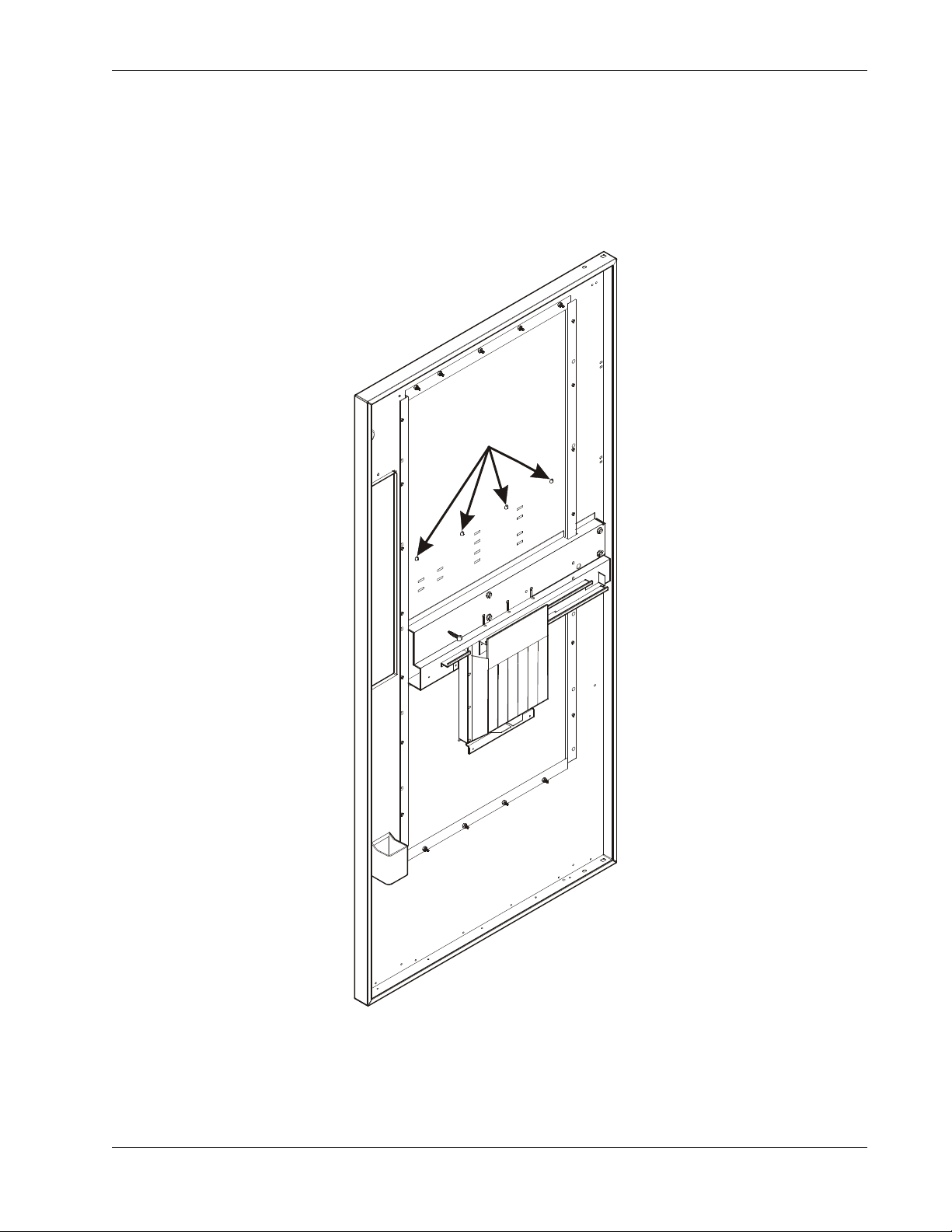
5. Set Up the Menu Assembly.
a. From the inside of the door, remove screws as indicated in the figure below.
b. Remove the menu board. If it is still held too tightly, repeat step 2.
c. Set up the menu board as desired and reinstall it in the reverse order of disassembly.
REMOVE
THESE
SCREWS
674p0005
November, 2007 33 6740001
Page 40
Programming The HotCup HotCup Operators’ Guide
Programming The HotCup
I. GETTING AROUND
Getting around the HotCup software is pretty easy once you know the features that are available to
you, and how to use them. The three main parts you will use are the SERVICE KEYPAD, the
SELECTION SWITCH PANEL, and the DISPLAY.
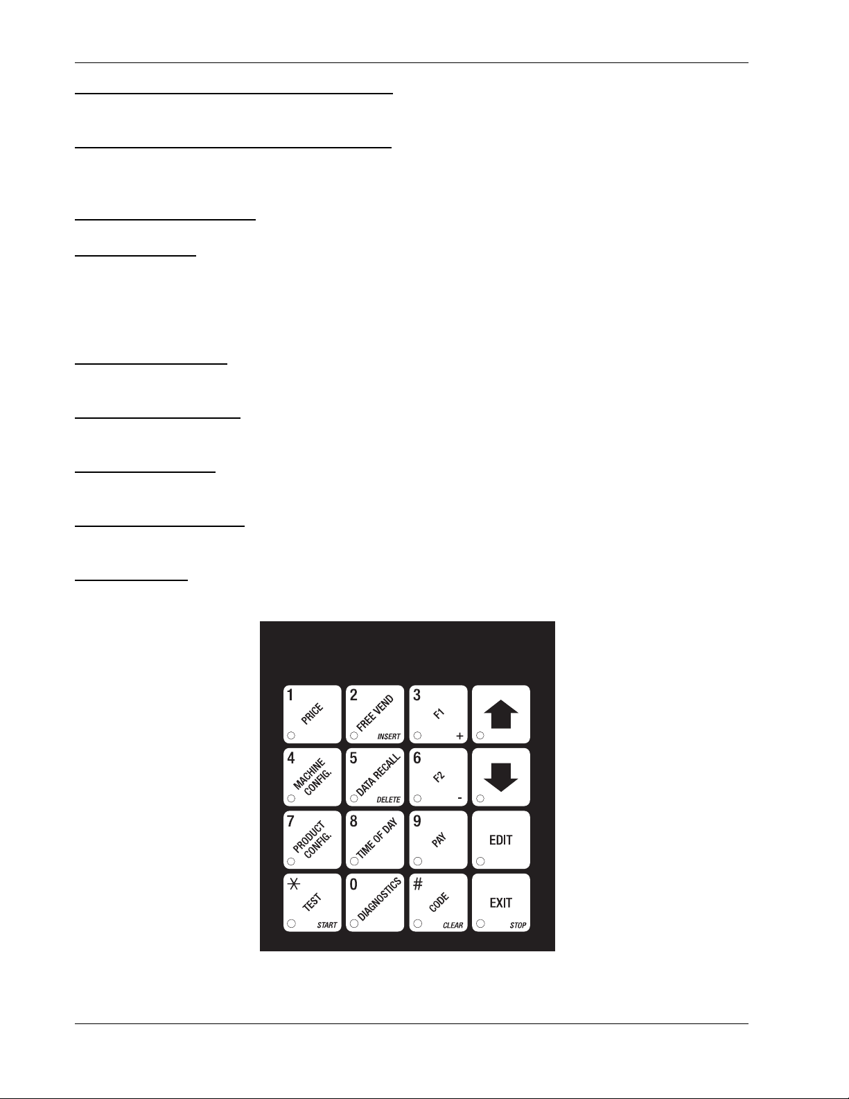
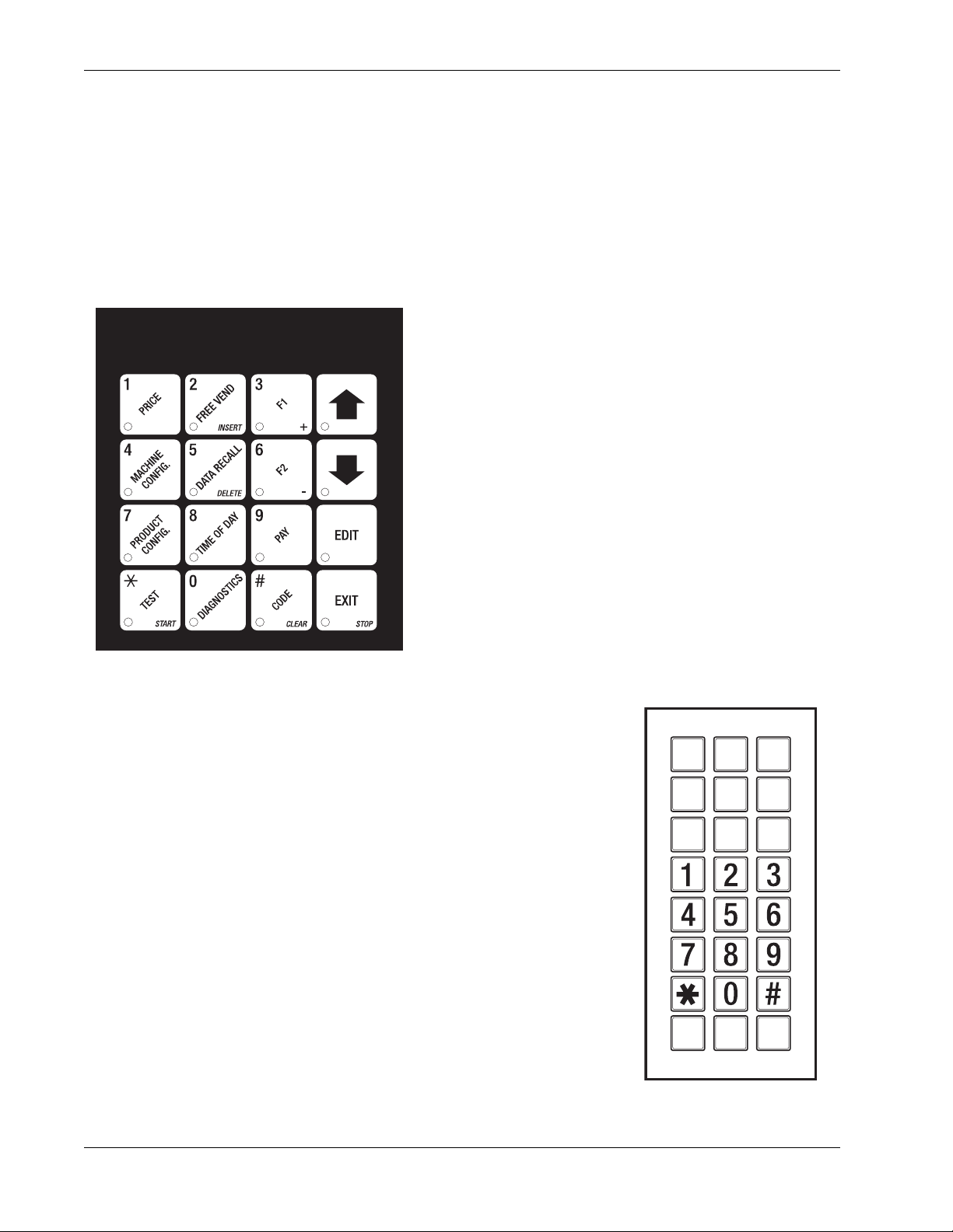
II. THE SERVICE KEYPAD
For most of your programming jobs, you will be using
the service keypad conveniently located on the
monetary panel. The service keypad has 16 keys. The
three columns on the left are the mode keys. The right
hand column contains the movement keys.
III. THE SELECTION SWITCH PANEL
The selection switch panel is also located on the monetary panel.
Unlike the service keypad, it is accessible when the cabinet door is
closed. These are the keys the customer will use to make selections.
You can also use these keys during programming procedures.
AB
C
DEF
H
J
G
XYZ
636P0044
6740001 34 November, 2007
Page 41
HotCup Operators’ Guide Programming The HotCup
IV. THE DISPLAYS
The 10-character display performs two functions, and is referred to in this book as "the display":
1. It shows the customer's selection and how much credit is in the machine, as well as the ready,
service, and time of day messages.
2. It provides information and feedback to the service person during maintenance.
DISPL
V. THE FUNCTION KEYS
The FUNCTION keys on the service keypad can be used for up to three things:
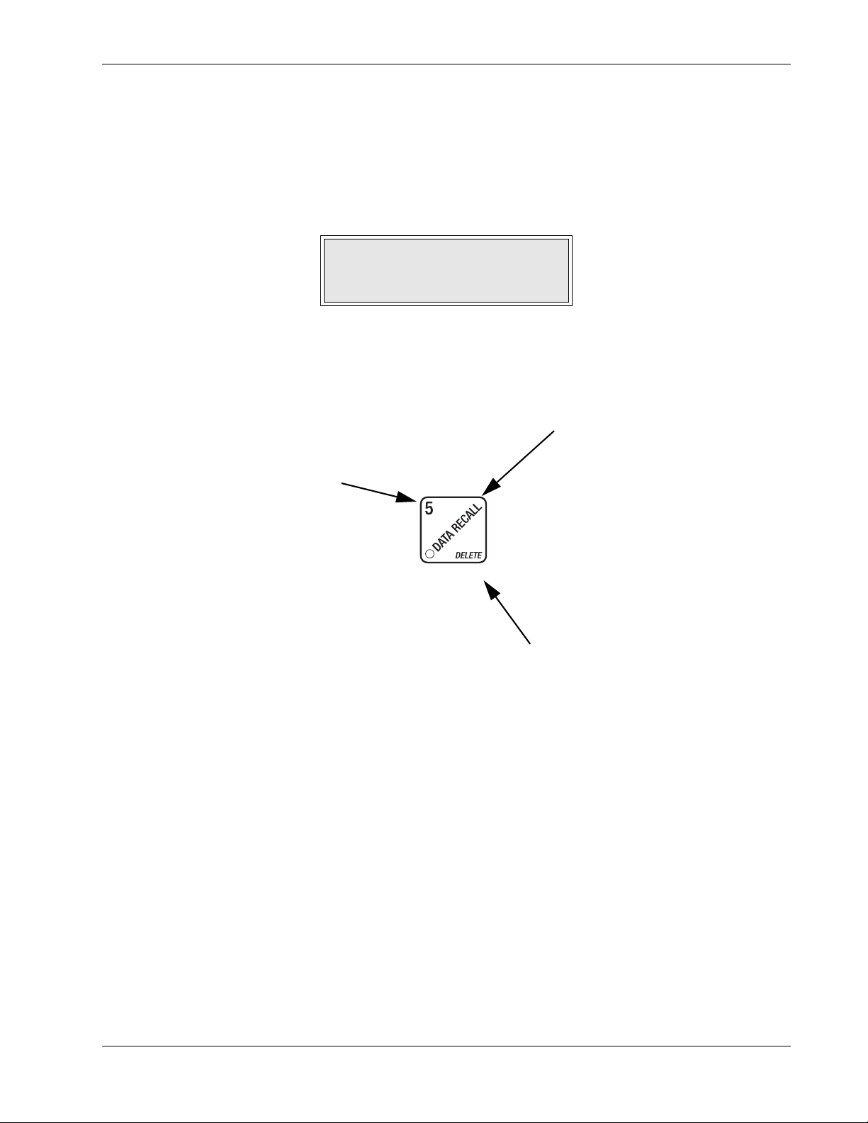
THE PRIMAR Y PURPOSE
THE NUMBER
You might be asked to
enter a numerical value.
You can do this in two
ways: pressing this key
is the same as pressing
the "5" on the selection
switch panel.
This is the main job of the
key. From the standby
message, it will allow you to
enter a programming mode.
In this example, you can
view stored sales.
THE SECONDARY
PURPOSE
This is the key's "second
job". This key can be used
to delete a character when
you are editing custom
messages.
November, 2007 35 6740001
Page 42
Programming The HotCup HotCup Operators’ Guide
VI. OTHER KEYS
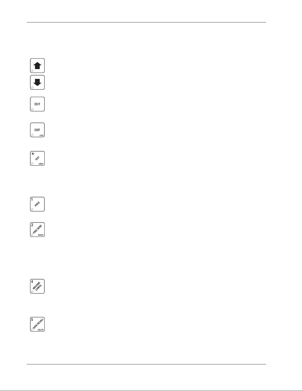
The MOVEMENT keys on the control panel let you move inside a mode, and back and forth between
modes. To see how these keys let you move around, study the flow diagram on the next page.
The up and down arrow keys are your "legs", which let you move up and down the list of
tasks. These keys are what let you continue from one step to the next in programming
procedures.
This is your "activate" or "choose" key. It "opens a door" to additional information and lets
you begin a programming task once you are inside of a mode. Sometimes, it is used as a
toggle switch to show you your choices during a programming task.
This is your "end" key. Pressing it one or more times will move you back to the start of the
mode, or all the way back to the standby message.
This key lets you start an action, such as a test.
VII. CONTROL PANEL SWITCHES EXPLAINED
Press this button to put your machine into the Price Setting mode. You can see maximum
and minimum machine prices, and change prices for entire machine or individual
selection.
Press this button to set up how the Free Vend mode will operate.
Press this button to view the water tank temperature, software version number, machine
and accessory configuration, and active selection status.
Press this button to:
• Select display language
• Select coin mechanism and options
• Select bill validator and options
Press this button to:
• View total sales and vends by whole machine, selection, or drink size
• Clear resettable data
• View or set machine
• Select card reader and options
• Select monetary options
• Set winner feature
6740001 36 November, 2007
Page 43
HotCup Operators’ Guide Programming The HotCup
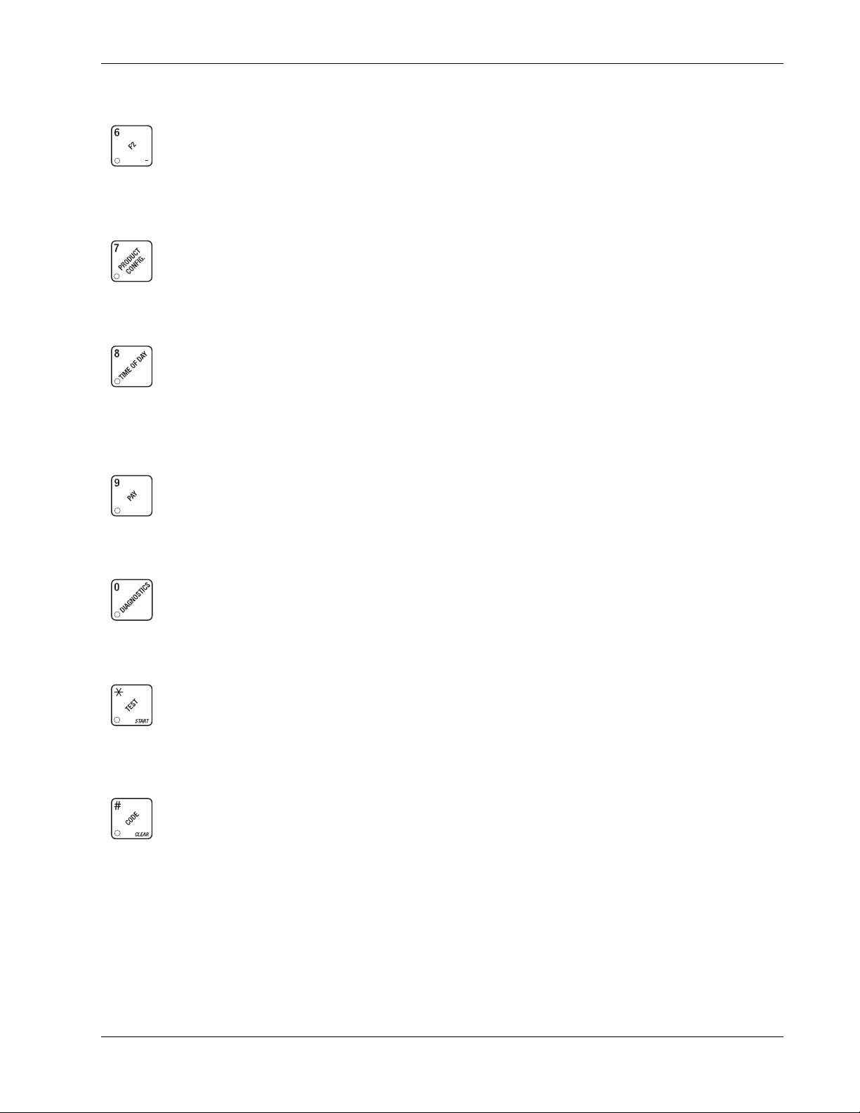
Press this button to:
• Download data into your portable data collection device (PDCD), OR
• Set printer baud rate, depending upon which device you are using
Press this button to:
• Set machine type configuration
• Set which selections are active
• Set up blended selections
• Set up cup sizes
Press this button to:
• Set time of day
• Set day, month, year
• Select display messages
• Press this button to pay one or more coins from the coin mechanism.
• Allows you to see any fault or condition that has placed the machine out of service
Press this button to:
• Perform test vends
• Test machine functions
• Set up time of day intervals for
inhibit, freevend, and discount
vending
• Edit messages
• Set message scrolling speed
• Test displays
• Fill the water tank
Press this button to:
• Enter the SUPERVISOR mode
• Change the SUPERVISOR access
code
November, 2007 37 6740001
• Lock and unlock access to
functions
Page 44
Programming Procedures HotCup Operators’ Guide
Programming Procedures
SOME CONVENTIONS
The pages that follow contain all the programming procedures for the HotCup. If you need to do a
specific task, you can find it immediately by using the Programming Index. Most of the procedures
have things in common, and here is a short guide to help you through these conventional
presentations:
• All programming procedures assume that you are starting with the standby message showing
in the display. If not, just press until you get there.
• Each programming procedure is highlighted by a pointing hand: so it will stand out.
• To exit a mode (CONTINUE) at any time, press . Sometimes you may have to press
the key more than once in order to exit all the way to the standby message.
• Text that looks like this:
monetary panel.
• Definitions and helpful information will appear in shadow boxes:
DISPLAY represents what you will see in the display on the
HELPFUL HINT
THE SUPERVISOR MODE
The supervisor is allowed to do things that a normal user cannot, like controlling access to certain
modes. The supervisor can lock out any of the programming modes to anyone who does not have
the right "key". Once a supervisor enters the proper code, he or she will be able to:
• Change the supervisor access code
• Lock out any or all of the service keypad modes
• Select whether price lines are used
• Set whether data is cleared after being downloaded into a portable data collection device
• Grant or deny access to data items during
• Modify the machine configuration
GAIN ACCESS TO THE SUPERVISOR MODE
a. Press . The display shows:
code within 6 seconds to gain access.
A new machine has a factory-set supervisor code of
ENTER CODE. You must enter the four-digit supervisor
DATA RECALL
NOTE
0000.
b. When you have entered the right code, you will hear two beeps and see
display.
6740001 38 November, 2007
UNLOCKED in the
Page 45
HotCup Operators’ Guide Programming Procedures
ENTER A NEW SUPERVISOR CODE
a. Follow the steps in (See “Gain Access to the Supervisor Mode” on page 38).
b. Press , then until the display shows
current supervisor code. Use the number keys to enter a new code.
IMPORTANT!
If you enter a new code, be sure to keep a written record of it.
There is no other way to access the SUPERVISOR mode.
c. CONTINUE.
ENTER A FREEVEND CODE
a. Follow the steps in (See “Gain Access to the Supervisor Mode” on page 38).
b. Press until the display shows
The X's represent the current freevend code. Use the number keys to enter a new code. If
the code is anything other than "
to enable free vends.
c. CONTINUE
FREE XXXX.
0000", it must be entered after the key lock is turned in order
SUPER XXXX. The X's represent the
LOCK OR UNLOCK MODE OR PAYOUT KEYS
a. Follow the steps in (See “Gain Access to the Supervisor Mode” on page 38).
b. Press until the display shows either
the number or character shown on the mode or payout key in question (1 through 9, # and *).
To see if a key is locked or unlocked, press that key.
c. Press to change between locked and unlocked. When anyone other than the supervisor
tries to enter a locked mode, the display shows
The following mode keys cannot be locked out:
d. CONTINUE.
X. LOCKED or X. UNLOCKED. "X" refers to
LOCKED.
NOTE
November, 2007 39 6740001
Page 46
Programming Procedures HotCup Operators’ Guide
SET PRINTER OR DEX OPTIONS
a. Follow the steps in (See “Gain Access to the Supervisor Mode” on page 38).
b. Press until the display shows:
PRINTER means that data will be sent directly to a printer,
OR
DEX ONLY means that data remains in memory after it is downloaded into a portable data
collection device (PDCD),
OR
DEX +CLR means that resettable data is cleared after it is downloaded into a PDCD.
c. Press to change between the three choices.
d. CONTINUE.
LOCK OR UNLOCK DATA CLEARING ACCESS
a. Follow the steps in (See “Gain Access to the Supervisor Mode” on page 38).
b. Press until the display shows either #
. UNLOCKED. LOCKED means that non-supervisors cannot clear resettable machine
#
sales and vend data from the key.
c. Press to switch between #
The supervisor can clear data regardl ess of this setting, provided
the supervisor code was correctly entered first.
d. CONTINUE
SELECT DISPLAY LANGUAGE
a. Press . The current LANGUAGE is shown in the display. Press to choose the
. LOCKED and #. UNLOCKED.
. LOCKED or
NOTE
desired language. Your choices are:
ENGLISH, DEUTSCH, FRANCAIS, ESPANOL,
PORTUGUESE, SWEDISH, or NEDERLANDS.
b. CONTINUE.
6740001 40 November, 2007
Page 47
HotCup Operators’ Guide Monetary Setup
Monetary Setup
SELECT COIN MECHANISM AND OPTIONS
a. Press , then press until the current COIN MECHANISM is shown in the display .
b. Press to choose the desired coin mechanism. Your choices are:
DUMB MECH,
MDB MECH, EXEC MECH, or NO MECH
NOTE
If you selected EXEC MECH you can exit the function.
c. Press until the display shows
Coins and bills which are less than or equal to this value will be returned without a purchase
being made.
Examples:
CHANGE X.XX.
CHANGE 0.00 Forced vend; NO change returned without a purchase.
CHANGE .25 Nickels, dimes, and quarters returned without purchase.
CHANGE 1.00 $1 bills and SBAs will be returned as change without purchase. Nickels,
dimes, and quarters are also returned.
d. Press until the display shows:
LOW.MSG X.XX. The display will show USE
EXACT CHANGE when the amount of available change in the coin mechanism falls below
the value of "
is displayed, the
worth of change is in the coin mechanism.
e. CONTINUE.
X.XX". Enter a value with the number keys. For example, if LOW.MSG 1.00
USE EXACT CHANGE message is displayed when less than a dollar's
November, 2007 41 6740001
Page 48
Monetary Setup HotCup Operators’ Guide
SELECT BILL VALIDATOR AND OPTIONS
a. Press , then press until one of the following is displayed:
NO DBV
SER.1.2.5.10.20
MDB.1.2.5.10.20
MDB. <*>
No bills will be accepted or there is no bill validator installed (you can
exit the function).
The serial bill validator is selected and will accept $1, $2, $5, $10,
and $20 bills. Use BILL SELECTION METHOD below to change
the bills which will be accepted.
A standard MDB bill validator is selected. It will accept $1, $2, $5,
$10 and $20 bills. Use BILL SELECTION METHOD below to
change the bills which will be accepted.
BILL SELECTION METHOD:
The standard $1, $2, $5, $10 and $20 bills are enabled by pressing
the 1, 2, 5, 6, or 7 ke y(s), respecti vely, to display which bill(s) will be
accepted.
An MDB bill validator which accepts nonstandard bills or tokens is
connected and operating. Press to enter list of bills.
(See “Initial Setup of a Nonstandard Bill Validator” on page 43).
BILL LIST OPERATION:
1. 1.00 ON
1. 1.00 OFF
TKN
Use and to scroll through the list of bills.
Use to turn the bill acceptance ON or OFF.
Use to move up to the top level screen.
1. = Bill validator channel 1, each bill has its own channel
1.00 = Bill value
ON = $1.00 bill will be accepted
OFF = $1.00 bill will not be accepted
Token bills (same as coupon bills)
6740001 42 November, 2007
Page 49
HotCup Operators’ Guide Monetary Setup
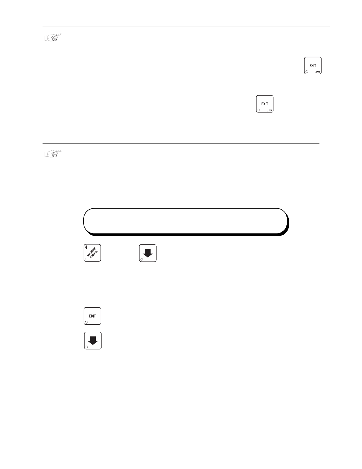
INITIAL SETUP OF A NONSTANDARD BILL VALIDATOR
a. Connect the bill validator, select MDB in the bill validator selection screens. The standard
MDB.1.2.5.10.20" screen will appear first. Exit the bill validator setup by pressing .
"
Bill information is now collected from the validator . Re-enter the bill validator selection screen
and the nonstandard screen "
PULSE DBV The pulse bill validator will accept $1 bills. Press to choose the
desired option.
b. CONTINUE.
SELECT MONETARY OPTIONS
This function lets you:
• Set declining balance,
• Set currency acceptance on low change,
• Set overbuy options,
• Set last bill stacking options
MDB. <*>" will appear.
Declining
Balance
a. Press , then press until one of the following is displayed:
Once Credit is established, multiple vends may
occur until the coin return is pressed
DECLINE.ON - More than one vend is allowed, with a declining balance.
OR
DECLINE.OFF - A declining balance is not allowed.
b. Press to display the desired choice.
c. Press until one of the following is displayed:
ACC <$$ X.XX The last bill which meets or exceeds maximum price will be held in escrow.
OR
ACC.STK X.XX The last bill which meets or exceeds maximum price and MDB coupon
bills (token bills) will be immediately stacked.
Example: If setting is
immediately stack the second $1.00 bill inserted.
November, 2007 43 6740001
ACC.STK 1.00 and maximum price is $1.50. This setting will
Page 50
Monetary Setup HotCup Operators’ Guide
d. Press to display the desired choice.
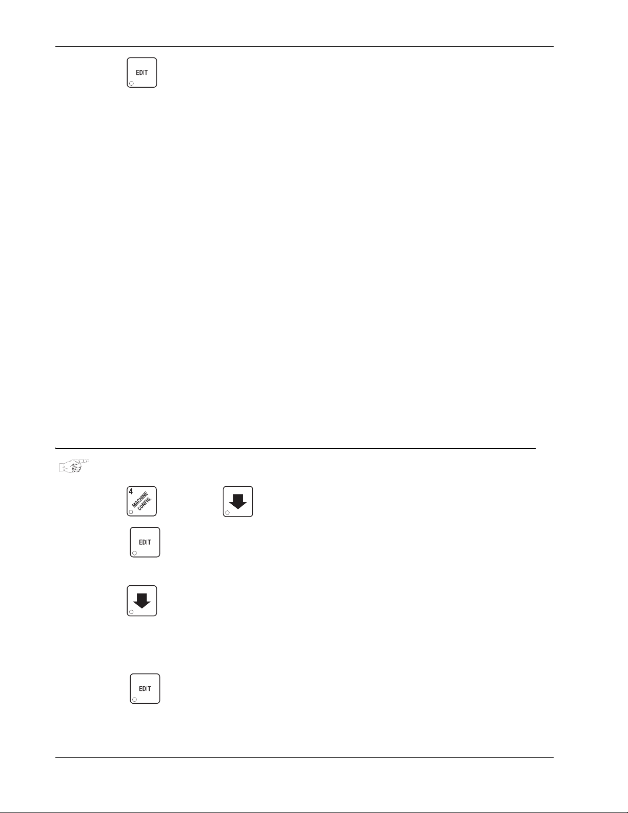
The value of "
i. First, "
enough change in the coin mech to cover all possible paybacks.
• For example, enter
is less than $1.00's worth of change. Entering
even though there is less than $5.00's worth of change, and so forth.
• Entering
to cover them.
ii. The value of "
product. The customer will be shortchanged when an overbuy occurs.
• For example, for a value of $0.25: if there is no change in the machine and the
customer inserts a $1.00 bill. The customer can purchase a product for $0.75 even
though the change cannot be paid back. The customer will be shortchanged.
Normally a purchase will not be approved unless all change can be paid.
• Entering 0.00 means that the vend will only be approved when the correct change can
be returned (overbuy disabled).
X.XX" has two purposes:
X.XX" tells the machine how big a bill or coin to accept even though there is not
1.00. The machine will take a dollar bill or coin even though the re
5.00 tells the machine to take a five
NOTE:
This could cause a customer to be shortchanged.
0.00 means that bills or coins will only be accepted if there is enough change
X.XX" tells the machine how much the customer is allowed to overbuy a
e. CONTINUE.
SELECT CARD READER AND OPTIONS
a. Press , then press until the current card reader is shown in the display.
b. Press to choose the desired card reader. Your choices are:
NO CARD, DUMB
CARD, or MDB CARD.
c. Press until one of the following is displayed:
REVALUE.ON Allows credit to be transferred onto the card
REVALUE.OFF Credit cannot be transferred to the card
d. Press to display the desired choice.
e. CONTINUE.
6740001 44 November, 2007
Page 51
HotCup Operators’ Guide Monetary Setup
PAYOUT COINS
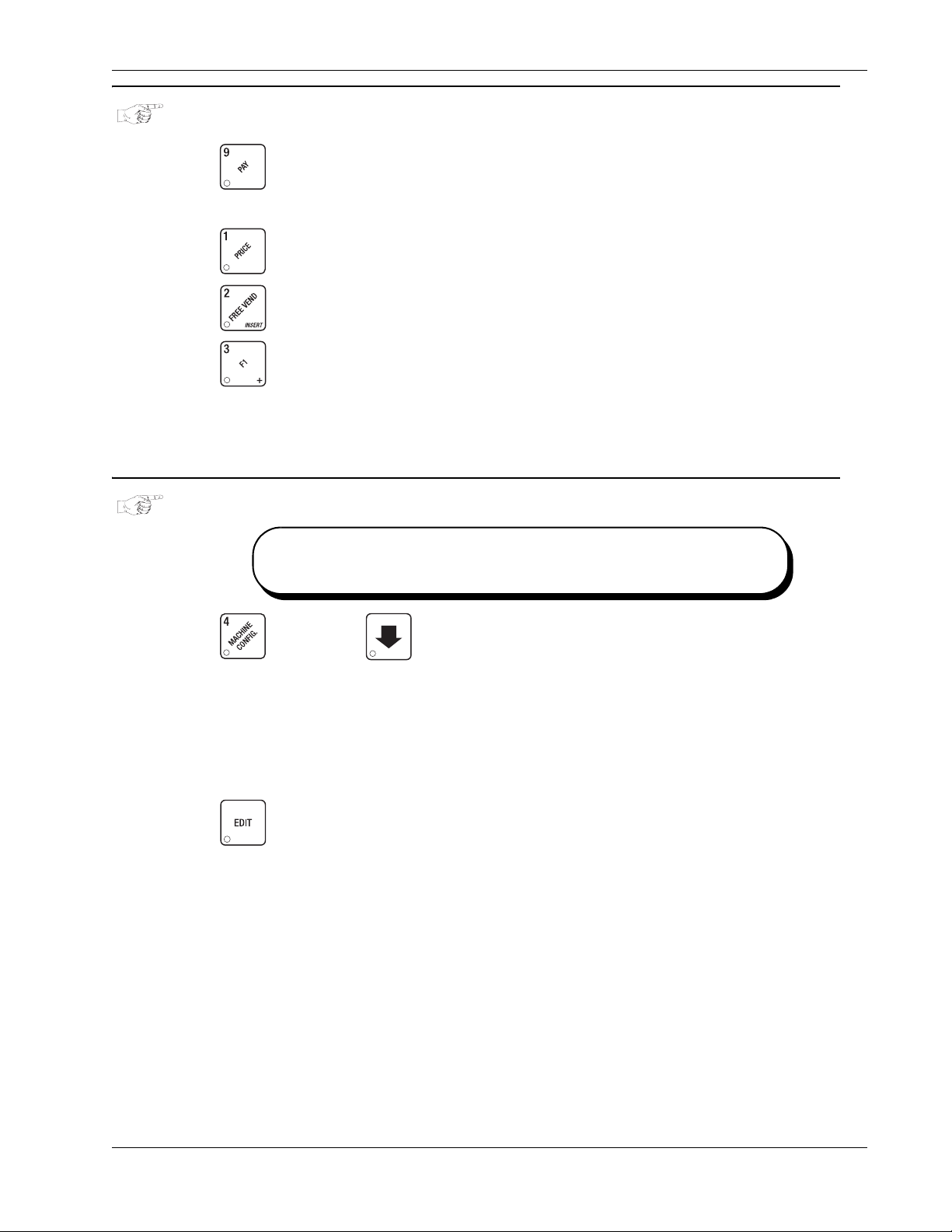
a. Press . If a dumb mech was selected, the display shows
was selected the display shows
b. Press . A dumb mech pays out one Nickel; an MDB mech pays a coin from tube 1.
Press . A dumb mech pays out one Dime; an MDB mech pays a coin from tube 2.
Press . A dumb mech pays out one Quarter; an MDB mech pays a coin from tube 3.
c. To continuously pay out coins, hold down the appropriate key.
d. CONTINUE.
SET UP WINNER MODE
Winner:
At pre-selected intervals, a customer may receive a
refund for a selection. You can select the intervals
and qualifying selections.
PAY 123.
NDQ =123; if an MDB mech
a. Press , then press until one of the following is displayed:
WINNER OFF Winner function is disabled.
OR
WIN XXX Winners are allowed at certain intervals, represented by "XXX".
b. Press to display the desired choice.
If you selected
c. The display shows
each winner vend. For example, an interval number of 50 means that a winner can happen
any one time during the next 50 vends. Using the number keys, enter an interval number
between 10 and 9999.
WINNER OFF, you can CONTINUE. Otherwise, go to the next step.
WIN XXX. XXX represents the number of vends that must occur per
November, 2007 45 6740001
Page 52

Monetary Setup HotCup Operators’ Guide
d. Press . The display shows * .---------. The dashes in the display represent which
selections are allowed winners. Press the appropriate letter key to enable a selection; press
the key again to disable it. For example, pressing A, C, and E will cause the display to look
like this: *
ADVANCED OPTIONS:
• Press to enable all selections; press to disable all selections.
•Press 0 or 1 to enable winners by cup size.
AN EXAMPLE . . .
You want to enable winners on all selections except E and F.
Do the following:
.A-C-E----, meaning that all A, C, and E selections can have a winner.
i. Press . The letters
ii. Press E and F. The letters
e. CONTINUE.
SET UP THE MUG DISCOUNT
a. Press , then press until the display shows
value of the discount customers will receive for using their own mugs or cups. Enter the
amount with the number keys. Enter 0 for no discount.
b. CONTINUE.
SET THE PRINTER BAUD RATE
a. Press . The display will show one of the following rates:
A through J appear in the display instead of the dashes.
E and F in the display are replaced by dashes.
MUG DSC XX. XX represents the
BAUD 1200, BAUD 2400, BAUD 4800, or BAUD 9600.
b. Press until the desired baud rate is displayed.
NOTE:
This baud rate must match that of your printer,
or it will not function properly.
c. CONTINUE.
6740001 46 November, 2007
Page 53
HotCup Operators’ Guide Monetary Setup
LOCK OR UNLOCK SELECTIONS
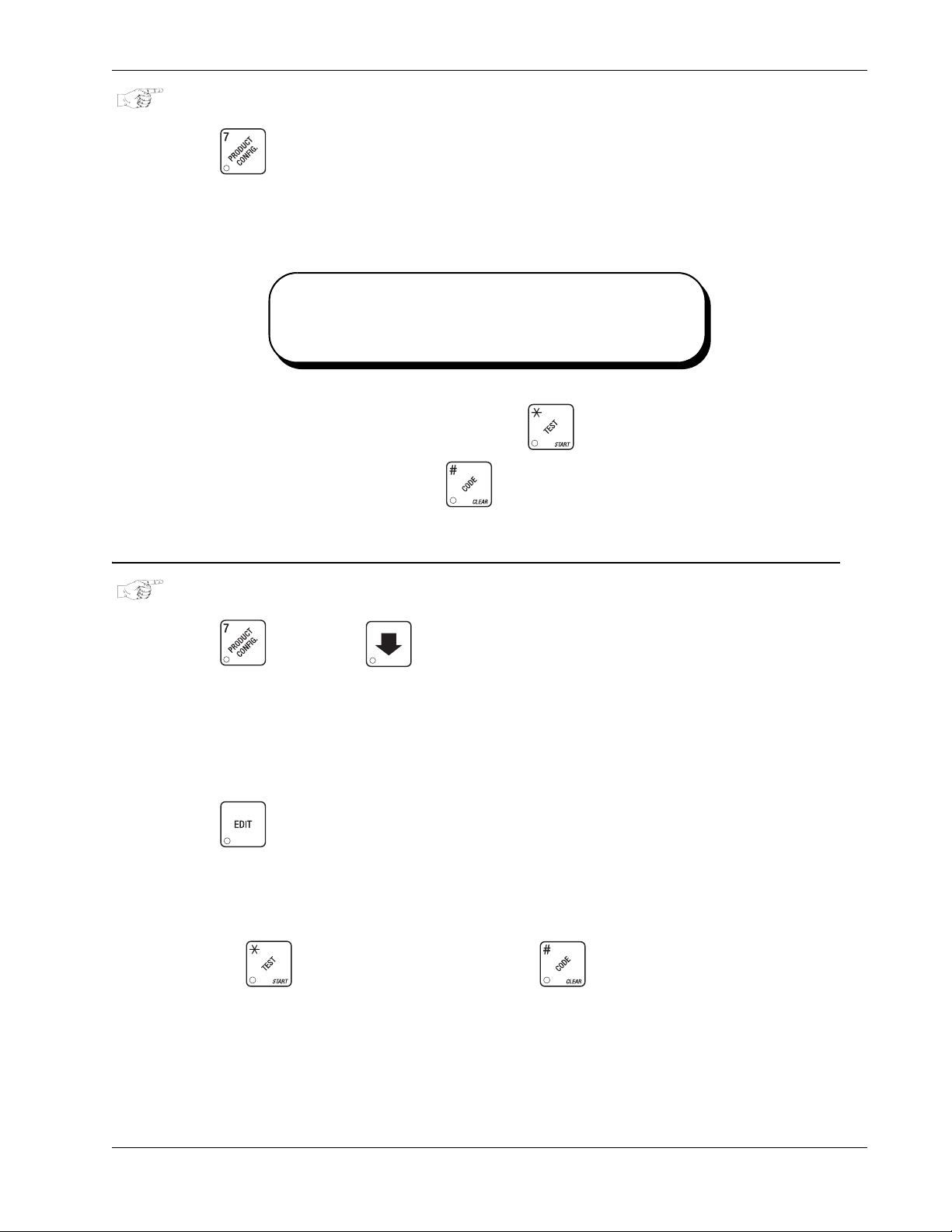
a. Press . The display shows
locked. Here, all selections are unlocked because they show up as dashes (-). Press the
appropriate selection letter to switch from locked to unlocked and back again. For example,
to lock out the "A" and "C" selections, press those letter keys on the selection switch panel.
For this example, the display will show
Selections can be LOCKED OUT (made unavailable for
vending). You may want to do this if there is a problem
with that slelection, such as no product in the canister.
You can lock all selections at once by pressing .
Unlock them all at once by pressing .
b. CONTINUE.
DISABLE SELECTIONS IN THE MERCHANDISER
LK. - - - - - - - . This shows a list of selections that are
LK. A - C - - - - .
a. Press , then press until the display shows something like this:
LK. ABCDEFGH. This display means that all regular size selections
(A - H) are not available for vending. An available selection has its letter replaced by a
blank space.
b. Press to display the second screen for X, Y, and Z selections.
c. Press the appropriate letter to toggle the display on or off.
NOTE
Press to lock all selections; press to unlock all selections.
November, 2007 47 6740001
Page 54
Monetary Setup HotCup Operators’ Guide
ASSIGN CUP SIZES TO SELECTIONS
(Supervisor Mode Only)
You can load up to two different sizes of cups in your machine (See “Assign Cup Sizes to Selections”
on page 48). You may not always want a certain selection to use all of the cup sizes in your
machine. For example, espresso is normally served in regular cups, so you probab ly will not want it
to be available in large or jumbo cups.
a. Press , then press , until the display shows something like this:
O.
ABCDEFGH. This display means that the smaller of the two cup sizes (0) is available for
selections (A-H).
b. Press to display all selections; press to clear all selections.
c. Press to display remaining selections (
represents the blended product, and the “2” represents the cup only selection.
NOTE:
If you have only one cup size in your machine, you will not see
the next display.
d. Press . The display shows something like this:
that the larger of the two cup sizes (1) is available for all selections (A - H).
e. Press the appropriate letter to toggle the display on or off. A selection that doesn’t vend the
displayed size cup has its letter replaced by a dash (-).
0 YZ2_ _ _ _ ). In this display, the “Y and Z”
1. ABCDEFGH. This display means
f. Press to display all selections; press to clear all selections.
g. Press to display remaining selections (1 YZ2_ _ _ _ ).
In this display, the “Y and Z” represents the blended product, and the “2” represents the cup
only selection.
To vend a cup only, press 1, 2, 3 (large size) or 2, 3 (regular size).
h. Continue.
6740001 48 November, 2007
Page 55
HotCup Operators’ Guide Hot Drink Setup
Hot Drink Setup
SET UP A HOT DRINK
Be sure that the cup sizes you set in (setup cup sizes page, ), agree with the cup sizes actually in
your machine. All procedures for setting up the hot drinks are similar, so this example will
demonstrate how to set up the A selection, regular size fresh brew coffee.
a. Press , then press until the display shows
the selection (A, B, etc.). The dash (-) represents the size of the selection.
b. Press A. (If you were setting up the A selection for the large size drink, you would press 1
first, then A.) The display shows
throw time for the A selection is 12.00 seconds. Enter a new time if desired.
c. Press . The display shows DRY. A .60. This means that the currently set dry product
throw time for the A selection is .60 seconds. Enter a new time if desired.
d. Pressing after each display will cause the following screens to appear:
WAT. A 12.00. This means that the currently set water
SETUP -*. The star (*) represents
DRY. A+ View and change the settings for an extra strong drink
SUG. A View and change the settings for the sugar throw time
SUG. A+ View and change the settings for extra sugar throw time
LIT. A View and change the settings for the lightener throw time
LIT. A+ View and change the settings for extra lightener throw time
SUB. A View and change the settings for the sugar sub throw time
SUB. A+ View and change the settings for extra sugar sub throw time
STP. A View and change the steep time
STP. A+ View and change the steep time for an extra strong drink
AIR. A View and change the air compressor/pump running time
dly. A View and change the amount of time after the vend to open the auto vend door
November, 2007 49 6740001
Page 56

Hot Drink Setup HotCup Operators’ Guide
WHIPPER OPTIONS
WHP. A XXX Press to view and change the whipper settings as follows:
ON- The last 3 seconds of the drink is always whipped
ON+ The whole drink is always whipped
OFF The drink is never whipped
opt See below
• If
J+ is selected (See “Set the Machine Type Configuration Code” on page 55):
OPT- The last 3 seconds of the drink is whipped only when the J key is pressed
OPT+ The whole drink is whipped only when the J key is pressed
• If
J- is selected(See “Set the Machine Type Configuration Code” on page 55):
OPT- The last 3 seconds of the drink is whipped unless the J key is pressed
OPT+ The whole drink is whipped unless the J key is pressed
DIFFERENCES:
Some selections will not show all of these items. The E selection will have some additional
selections:
WA.2 E View and set the water throw time for the cappuccino second product (chocolate)
DR.2 E View and set the chocolate throw time for cappuccino
PCT. E To automatically compute new times for cappuccino, enter a percentage, then
press . This percentage represents the amount of chocolate product in
cappuccino, versus that in a normal chocolate drink. This time and the normal
coffee settings will compute the new cappuccino time.
(This is a handy way to move from one selection to another without going to the
screen first.)
If you try to set up a selection that is not configured, the
display.
OPTIONS:
i. At any of the preceding displays, you can press to test throw that item.
ii. At any of the preceding displays, you can press * or # (on the selection switch panel) to
step through a list of that item’s throw times for other selections where that item is active.
For example, pressing # at the
is a handy way to move from one selection to another without going to the
first.
If you try to set up a selection that is not configured, the
screen will remain in the display.
e. Continue.
WAT. A display will show the throw time for WAT. B. This
NOTE
SETUP screen will remain in the
SETUP
SETUP
SETUP screen
6740001 50 November, 2007
Page 57
HotCup Operators’ Guide Hot Drink Setup
VIEW OR SET THE HOT WATER TANK TEMPERATURE
a. Press then until the display shows
water tank temperature setpoint in degrees Fahrenheit. If a decimal point appears ne xt to the
“F”, the heater is on.
b. If desired, enter a new setpoint in the accepted range of 149° - 205° F (65° - 96° C).
NOTE
The lower limit for vending is 20° below setpoint, up to a
maximum of 180° F (82° C).
c. To change display units (replace the “F” with a “C” for Celsius), press .
d. Continue.
SET UP LOW TEMPERATURE DISPENSING
a. Press then press until the screen displays either:
SET 202 °F . In this example, 202° is the
LTDIS off. This causes the machine to operate the same as the previous HotCup Center.
For example, with a setpoint temperature of 202º F the machine will in hibit vending when the
water tank temperature reaches 182º F.
-or-
ltdis on. Allows vending to a water tank temperature of 140º F.
b. Press to change between ON and OFF.
c. Continue.
November, 2007 51 6740001
Page 58
Hot Drink Setup HotCup Operators’ Guide
SET UP LOW POWER SETTINGS
Low power settings allow for the water tank to be se t to a lower temperature at up to 4 dif ferent dates
and times. For example, you want to lower the tank temperature to 160º F overnight on Mondays
through Fridays. The machine tank temperature setpoint will be changed to 160º F at 6:00 pm and
maintained at that temperature until 5:00 am on the following morning when the setpoint is returned
to 202º F. Please keep in mind that at 5:00, the machine will just begin to increase to the 202º F
setpoint temperature. It is up to you to determine how long that will t ake and to allow enough time for
the tank to be at its proper temperature when the machine will be used. Typically, one hour is
adequate to return to the normal operating temperature.
NOTE:
The machine OUT OF SERVICE condition during the low power interval will be
determined by how you have set the LTDIS configuration.
a. Press then press until the screen displays
b. Press the number of the time interval you want to edit, or to edit time interval 1( we will
use interval 1 for this example.
c. The display shows
interval (represented by 1) is on or off. Press to change the condition of the time
interval.
d. If you turn an interval ON, it must be edited. You can edit a time interval now, then turn it
OFF until another time.
e. Press . The display shows
a new start time (24-hour format) for this interval. To enter the time for 6:00 pm, enter 1800.
f. Press . The display shows
a new stop time (24-hour format) for this interval. To enter the time for 5:00 am, enter 0500.
low.pw ON or low.pw Off. This display tells you whether your time
1.STRT X.XX.. X.XX is the currently set start time. Enter
1.STOP X.XX.. X.XX is the currently set stop time. Enter
LOW.PWR.
g. Press . The display shows
time interval is active. Pressing number keys 1 through 7 switches the days on/off. For
example, press “2”, “3”, “4”, “5”, and “6”. The display now shows
This interval is active on Monday through Friday.
6740001 52 November, 2007
1.@ - - - - - - -. The dashes represent the days that this
1.@ - M t W t F -.
Page 59
HotCup Operators’ Guide Hot Drink Setup
SET THE RATIO OF CHOCOLATE IN CAPPUCCINO
a. Press , then press until the display shows either:
RA TIO XX "XX" is the percent age of chocolat e cont ained in a cappuccino drink or RATIO
No ratio is selected.
OFF
b. Press to switch between these two displays. To change the value of
enter the numbers directly . This is a quick way to set up your cappu ccino drinks. You can set
a ratio close to your taste, turn ratio OFF, then alter the product throw.
NOTE
Leaving this step with
E and I selections. Leaving this step with a ratio set will alte r those setting s. The ratio
automatically selects the times for water and dry product throw. The E and I
selections no longer appear in the displays for those steps. If you desire greater
control over your cappuccino drinks, leave ratio OFF.
c. CONTINUE.
SET THE BREWER RINSE TIME INTERVAL
a. Press , then press until the display shows
the time of day (in hours and tenths of hours) the machine rinses the brewer. For example,
RATIO OFF displayed does not alter any previous settings for
SAN.TIM X.X. "X.X" represents
RATIO XX,
SAN.TIM 4.5 means that brewer rinse takes place at 4:30 am. Use the number keys to
enter a new time, if desired. Range: 0.0 - 23.9 in .1 hour (6 minutes) increments.
b. Press . The display shows
rinses the brewer after the last brewed selection. For example,
brewer rinse takes place 2.5 hours after the last vend. Use the number keys to enter a new
time, if desired. Range: 2.0 - 12.5 hours, in .1 hour (6 minutes) increments.
c. CONTINUE.
November, 2007 53 6740001
SAN.HRS X.X. "X.X" represents how soon the machine
SAN.HRS 2.5 means
Page 60
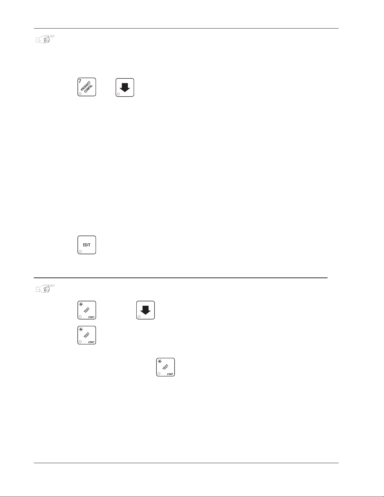
Hot Drink Setup HotCup Operators’ Guide
SET THE BOWL RINSE TIME
Mixing bowl(s) can be automatically rinsed by one of two methods: You can specify a set time of day
when the bowl is rinsed, or you can specify that rinsing takes place a set time after the last selection
is vended.1.
a. Press then until the display shows one of the following:
RIN.HRS 2.5 - This is how soon the machine rinses the bowls after a vend. In this example,
bowl rinse takes place 2.5 hours after the last vend. Range: 2.0 - 12.5 hours, in .1 hour (6
minute) increments.
-or-
RIN.TIM 4.5 - The time of day (in hours and tenths of hours) the machine rinses the bowls.
In this example, bowl rinse takes place at 4:30 am. Range: 0.0 - 23.9 in .1 hour (6 minute)
increments.
NOTE:
If 24 hours passes without a vend, no rinsing will t ake pl ace. This
eliminates unnecessary rinsing over a weekend or holiday.
-or-
RINSE OFF - No bowl rinse takes place.
b. Press to switch between these options, and the number keys to enter new values.
c. Continue.
CLEAR TANK ERRORS AND FILL THE TANK
a. Press , then press until the display shows
b. Press . This clears any tank error and start s filling the tank, if necessary. If it is taking
a long time to fill the tank AND THERE ARE NO LEAKS, you may see
diagnostic list again. Just press again after making sure there are no other problems,
such as a restriction in the water inlet line or a clogged water filter.
c. Continue.
TANK FILL.
TANK ERR in the
6740001 54 November, 2007
Page 61
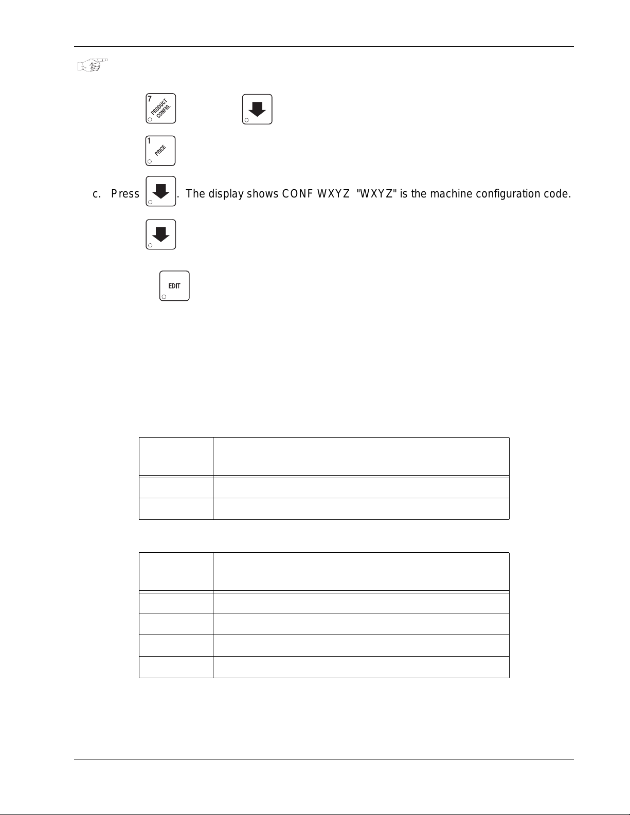
HotCup Operators’ Guide Hot Drink Setup
SET THE MACHINE TYPE CONFIGURATION CODE
(Supervisor Mode Only)
a. Press , then press until the display shows Mach.type (x).
b. Press to enter MACH.TYPE (1).
c. Press . The display shows CONF WXYZ "WXYZ" is the machine configuration code.
c. Press until the display shows D+J+ WXYZ. “D” is the automatic delivery door status.
A plus sign (+) means the door is on; a dash (-) means the door is off. Toggle this setting by
pressing . “J” is the whipper setting. Toggle a plus sign (+) or a dash (-) with the J key.
(See “Whipper Options” on page 50).
“W” represents the machine type, “X” is the soup and sugar substitute configuration, “Y” is the
brewer configuration, and “Z” is canister mapping. The following tables give the possible
values for each of the four numbers. Enter the appropriate configuration code for your
machine.
d. CONTINUE.
ENTER
FOR (W)
ENTER
FOR (X)
MACHINE TYPE CONFIGURATION
DEFINITION
1 Freeze Dried Use
5 Single Fresh Brew or Dual Fresh Brew
SOUP AND SUGAR SUBSTITITUE CONFIGURATION
DEFINITION
1 Canister 5 is not used
2 Canister 5 present, but receives no condiments
3 Canister 5 present, may receive condiments
4 Water Only
November, 2007 55 6740001
Page 62
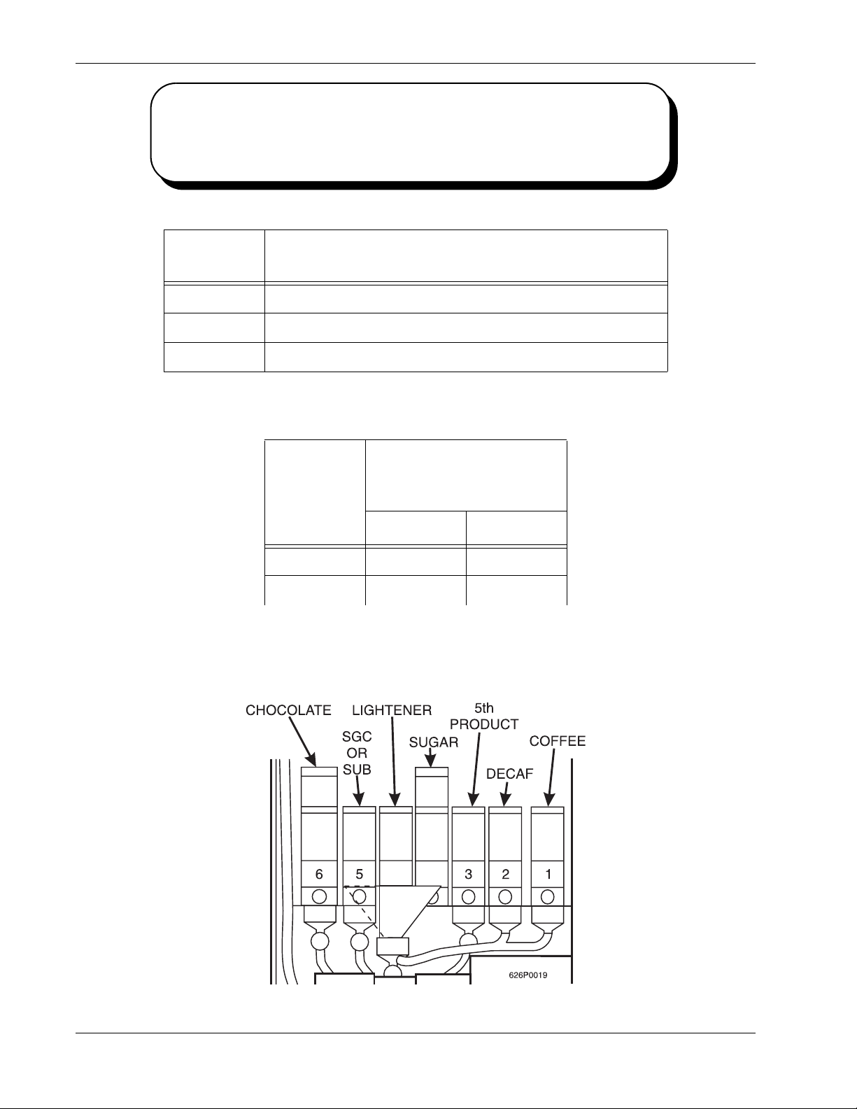
Hot Drink Setup HotCup Operators’ Guide
SINGLE BREW
DUAL BREW
ENTER
FOR (Y)
1 Single Brew - Cofffee (Model 6
2 Dual Brew - Coffee and decaf coffee (Model 674)
6Freeze Dried
A machine with only one brewed selection (the second
selection is freeze dried). Uses a single barrel brewer.
A Machine with two brewed selections. uses a single
barrel brewer.
BREWER CONFIGURATION
DEFINITION
74)
CANISTER MAPPING (SEE FIGURE BELOW)
ENTER
FOR (Z)
MENU SELECTION
LETTERS FOR
CANISTER NUMBERS
21
1BA
2AB
Index: A=Coffee B=Decaf
6740001 56 November, 2007
Page 63
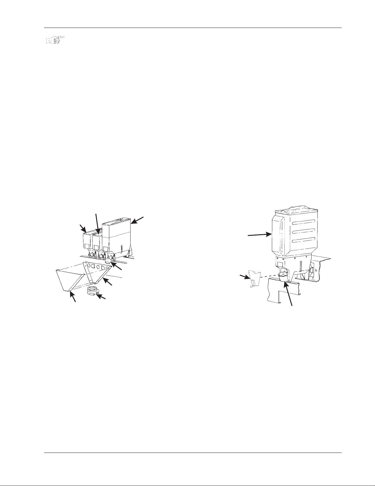
HotCup Operators’ Guide Product Configuration
S
S
Product Configuration
COLLECTING DRY PRODUCT GRAM THROWS
Measuring the gram throw allows you to get the right amount of dry product or condiment into your
hot drink. To do this, you need a container to catch the product throw and an accurate gram scale to
measure its weight.
a. Make a measuring container by cutting down a p aper cup until it fits under the canister spout
as shown.
b. Weigh the measuring cup and zero the gram scale accordingly.
c. Make 5 test throws as instructed in the programming steps, then average the results.
d. Weigh the test throw.
e. Repeat steps 3 and 4 until you get the correct product or condiment weight.
Tables D1 and D2 show the factory default settings for the various dry products sold by the
merchandiser. They are good starting points for you to use in setting up your machine. In the end,
the amount of dry product or condiments you use in your drinks depends upon taste and
manufacturers’ recommendations. Recommended weights and times are for guidance only, and you
do not have to adhere to them.
UGAR
UBSTITUTE
COVER
LIGHTENER
MIXING
BOWL
CHUTE
SUGAR
CUP POSITION
FOR TEST
THROW
FRESH BREW
COFFEE
CANISTER
CHUTE
CUP POSITION
FOR TEST THROW
Collecting Condiment Throws Collecting Ingredient Throws
November, 2007 57 6740001
Page 64

Product Configuration HotCup Operators’ Guide
DRY PRODUCT WEIGHT AND THROW TIME FACTORY DEFAULT SETTINGS
WEIGHT (IN GRAMS) PER SIZE CUP
SELECTION
AFresh Brew Coffee
A Freeze Dry Coffee
A Strong freeze dry coffee
B Fresh brew decaf
B Freeze dry decaf
B Strong freeze dry decaf
Fresh brew coffee
D
ESPRESSO
Freeze dry coffee
D
ESPRESSO
THROW TIMES (IN SECONDS) PER SIZE CUP
5oz 7oz 8oz 9oz 10oz 12oz
5.70
1.60
0.90
0.35
1.10
0.65
5.70
1.60
0.90
0.35
1.10
0.65
5.70
1.60
0.90
0.35
8.00
2.20
1.20
0.50
1.50
0.90
8.00
2.20
1.20
0.50
1.50
0.90
8.00
2.20
1.20
0.50
9.00
2.50
1.50
0.60
1.80
1.10
9.00
2.50
1.50
0.60
1.80
1.10
9.00
2.50
1.50
0.60
10.00
2.80
1.60
0.65
2.00
1.20
10.00
2.80
1.60
0.65
2.00
1.20
10.00
2.80
1.60
0.65
11.00
3.10
1.80
0.70
2.20
1.35
11.00
3.10
1.80
0.70
2.20
1.35
11.00
3.10
1.80
0.70
13.00
3.65
2.20
0.90
2.60
1.60
13.00
3.65
2.20
0.90
2.60
1.60
13.00
3.65
2.20
0.90
Strong freeze dry coffee
D
ESPRESSO
Fresh brew coffee
E
CAPPUCCINO
Freeze dry coffee
E
CAPPUCCINO
Strong freeze dry coffee
E
CAPPUCCINO
F Instant tea
F Strong instant tea
GChocolate
HSoup
H Soluble Product
1.10
0.65
5.70
1.60
0.90
0.35
1.10
0.65
0.90
0.70
1.10
0.90
17.00
2.80
4.30
0.70
10.0
2.45
1.50
0.90
8.00
2.20
1.20
0.50
1.50
0.90
1.20
1.00
1.50
1.25
24.00
4.00
6.00
1.00
13.5
3.35
1.80
1.10
9.00
2.50
1.50
0.60
1.80
1.10
1.50
1.25
1.80
1.60
28.00
4.65
7.00
1.15
16.2
4.00
2.00
1.20
10.00
2.80
1.60
0.65
2.00
1.20
1.60
1.30
2.00
1.75
31.00
5.15
7.60
1.25
17.8
4.35
2.20
1.35
11.00
3.10
1.80
0.70
2.20
1.35
1.80
1.60
2.20
1.85
34.00
5.65
8.50
1.35
19.7
4.85
2.60
1.60
13.00
3.65
2.20
0.90
2.60
1.60
2.20
1.85
2.60
2.10
41.00
6.80
10.20
1.65
23.7
5.80
6740001 58 November, 2007
Page 65
HotCup Operators’ Guide Product Configuration
DRY PRODUCT WEIGHT AND THROW TIME FACTORY DEFAULT SETTINGS (CONTINUED)
WEIGHT (IN GRAMS) PER SIZE CUP
SELECTION
D Sugar used in espresso
D Extra sugar used in espresso
E Sugar used in cappuccino
E Extra sugar used in cappuccino
F Sugar used in tea
F Extra sugar used in tea
F Lightener used in tea
F Extra lightener used in tea
F Sugar substitute used in tea
THROW TIMES (IN SECONDS) PER SIZE CUP
5oz 7oz 8oz 9oz 10oz 12oz
2.10
0.35
3.00
0.50
3.50
0.45
4.60
0.60
4.20
0.55
5.50
0.70
1.20
0.70
1.50
0.85
0.60
0.75
3.00
0.45
4.35
0.65
5.10
0.65
6.80
0.90
6.00
0.75
8.00
1.00
1.50
0.85
2.00
1.15
0.85
1.05
3.50
0.55
4.80
0.75
6.00
0.75
7.70
1.00
7.00
0.90
9.00
1.15
2.00
1.15
2.50
1.45
1.00
1.25
4.00
0.60
5.35
0.80
6.80
0.85
8.50
1.10
8.00
1.00
10.00
1.25
2.50
1.45
3.00
1.70
1.10
1.35
4.50
0.65
6.25
0.90
7.70
0.95
9.40
1.20
9.00
1.15
11.00
1.40
3.00
1.70
3.50
2.00
1.30
1.60
5.50
0.80
7.20
1.05
9.40
1.20
11.00
1.45
11.00
1.40
13.00
1.65
4.00
2.25
4.50
2.60
1.50
1.90
F Extra sugar substitute used in tea
*-* Sugar
*-* Extra sugar
*-* Lightener
*-* Extra lightene
*-* Sugar substitute
*-* Extra sugar substitute
D= Espresso E= Cappuccino I= Cocolate times for cappuccino
* The actual gram weight of a product or condiment throw will vary depending upon the type of product or condiment used.
The weights given are approximate based upon factory testing.
*-* Separate sugar, lightener, and sugar substitute timers are available for selections A/B/C, D, E, and F.
0.80
1.00
4.20
0.55
5.50
0.70
1.20
0.70
1.50
0.85
0.60
0.75
0.80
1.00
1.10
1.35
6.00
0.75
8.00
1.00
1.50
0.85
2.00
1.15
0.85
1.05
1.10
1.35
1.30
1.60
7.00
0.90
9.00
1.15
2.00
1.15
2.50
1.45
1.00
1.25
1.30
1.60
1.40
1.75
8.00
1.00
10.00
1.25
2.50
1.45
3.00
1.70
1.10
1.35
1.40
1.75
1.60
2.00
9.00
1.15
11.00
1.40
3.00
1.70
3.50
2.00
1.30
1.60
1.60
2.00
1.90
2.40
11.00
1.40
13.00
1.65
4.00
2.25
4.50
2.60
1.50
1.90
1.90
2.40
November, 2007 59 6740001
Page 66
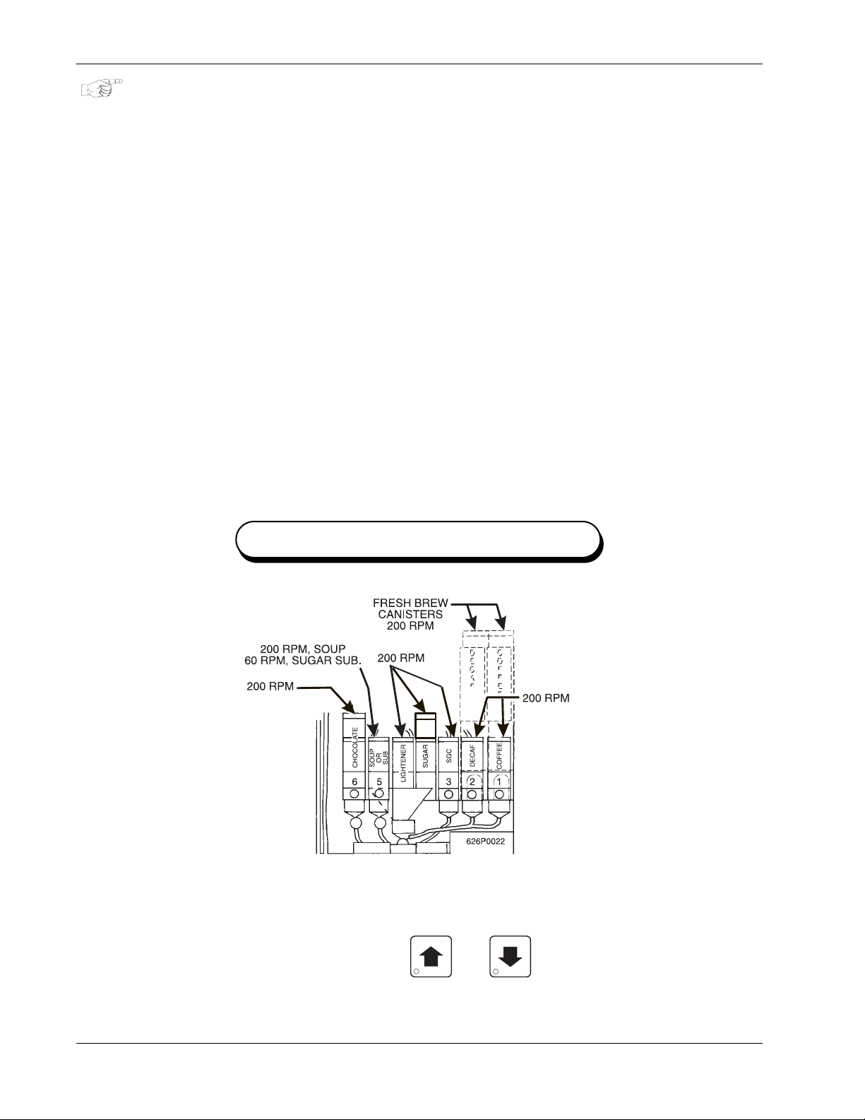
Product Configuration HotCup Operators’ Guide
CAPPUCCINO
Cappuccino is made with various ratios of chocolate to cof fee, according to taste. Lightener (E timer)
is also used for cappuccino. For an example, the default chocolate-to-cof fee ratio of 15/ 85 in a 8.2 5
oz. cup consists of the following:
• A chocolate throw (DR.2) lasting .65 seconds, providing 15% of the normal chocolate throw
(approximately 5.4 grams*).
• A water throw for the chocolate (WA.2) lasting 2.65 seconds (chocolate product throw plus 2
seconds to ensure the mixing bowl is fully rinsed). The volume is about 59 ml, depending
upon how the flow rate is adjusted.
• A throw for cappuccino coffee (product E) equal to a normal coffee (product A) throw.
• A water throw for the freeze dry coffee selection (water E) lasting for 5.55 seconds (132 ml).
OR
• A water throw for the fresh brew coffee selection (water E) lasting for 5.55 seconds (153 ml).
In either case the water volume is enough to fill the remainder of the cup.
The actual mixing sequence is as follows:
a. The coffee portion of cappuccino is made using the same canister/valve combination as the
normal (A) coffee.
b. After the coffee is completely in the cup, the chocolate portion is made with the selection G
canister/valve combination. This gives the drink its traditional "layering"
* Chocolate weights will vary with different brands.
MOTOR SPEED BY LOCATION
HINTS:
To “fine tune” your Cappuccino drink to your exact taste, set a ratio close to what you like (between
5% and 50%). Adjust the individual timers using and until you are satisfied. You may
find it necessary to cut down on the amount of sweetener available to a cappuccino drink with a high
ratio of chocolate, as the chocolate contains sweetener of its own.
6740001 60 November, 2007
Page 67
HotCup Operators’ Guide Product Configuration
CAFFE LATTE
Caffe Latte has a rich, robust coffee flavor. It is a full-bodied hot beverage with extra creamer,
whipped to frothy perfection, with sugar optional. Try this recipe to expand your gourmet product
selections and increase premium pricing opportunities.
ENTER THE SUPERVISOR CODE
a. Press . The display shows:
code within 6 seconds to gain access.
A new machine has a factory-set supervisor code of
When you have entered the right code, you will hear two beeps and see
the display.
SET UP YOUR SELECTION
Follow the instructions in the PRODUCT CONFIGURATION section of this HotCup
Operators’ Guide.
a. Make sure the machine is configured to use 12 oz. cups.
b. Set up the 1D selection as follows:
a. Coffee: 17 grams
b. Sugar: 2.5 grams
c. Lightener: 5 grams
d. Water: 6 ounces (about 177 ml)
e. Steep time: 12.5 seconds
f. Whip: ON +
To get these measurements, refer to PRODUCT CONFIGURATION.
ENTER CODE. You must enter the four-digit supervisor
NOTE
0000.
SUPERVISOR in
See COLLECTING DRY PRODUCT GRAM THROWS, and perform test throws of the dry
ingredients. See COLLECTING WATER THROWS, and perform test water throws.
November, 2007 61 6740001
Page 68
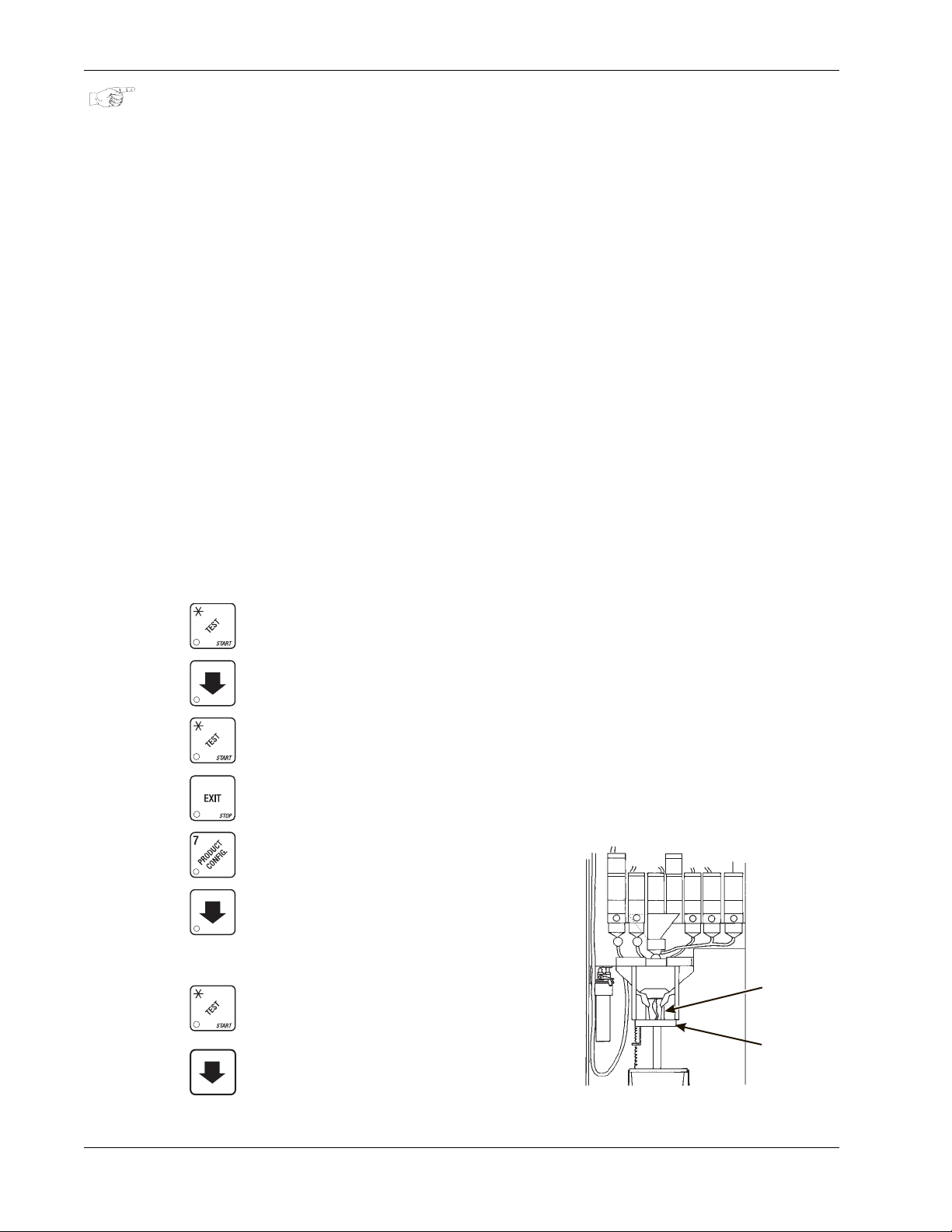
Product Configuration HotCup Operators’ Guide
G
S
COLLECTING WATER THROWS
National Vendors recommends the factory default times be used for water throws to ensure proper
mixing. Table W1 gives the factory default water throw times for the various size cups and product
selections.
WARNING
Water is EXTREMELY HOT! Be careful.
For a non-brewed selection, collect the water throws as follows:
a. Place a cup in the cup delivery station.
b. Ensure the merchandiser is using the factory defaults for the cup sizes (refer to PRODUCT
CONFIGURATION).
c. Initiate the water throw for a selection.
d. Remove the cup and pour the water into a graduated cyclinder.
e. Refer to table W1 for the correct volume of water.
f. Adjust the water valve for that selection and repeat steps 3 through 5 until the correct volume
of water is thrown.
For a brewed selection, collect the water throws as follows:
a. Place a cup in the cup delivery station.
b. Press .
c. Press to brewer test.
d. Press twice to clamp brewer closed.
e. Press .
f. Press ..
g. Press to setup.
h. Enter “A” or “B”.
i. Press . (Listen for water valve to close.)
CUP FOR TAKIN
WATER THROW
CUP DELIVERY
_
STATION
j. Press to air (pump).
6740001 62 November, 2007
Page 69
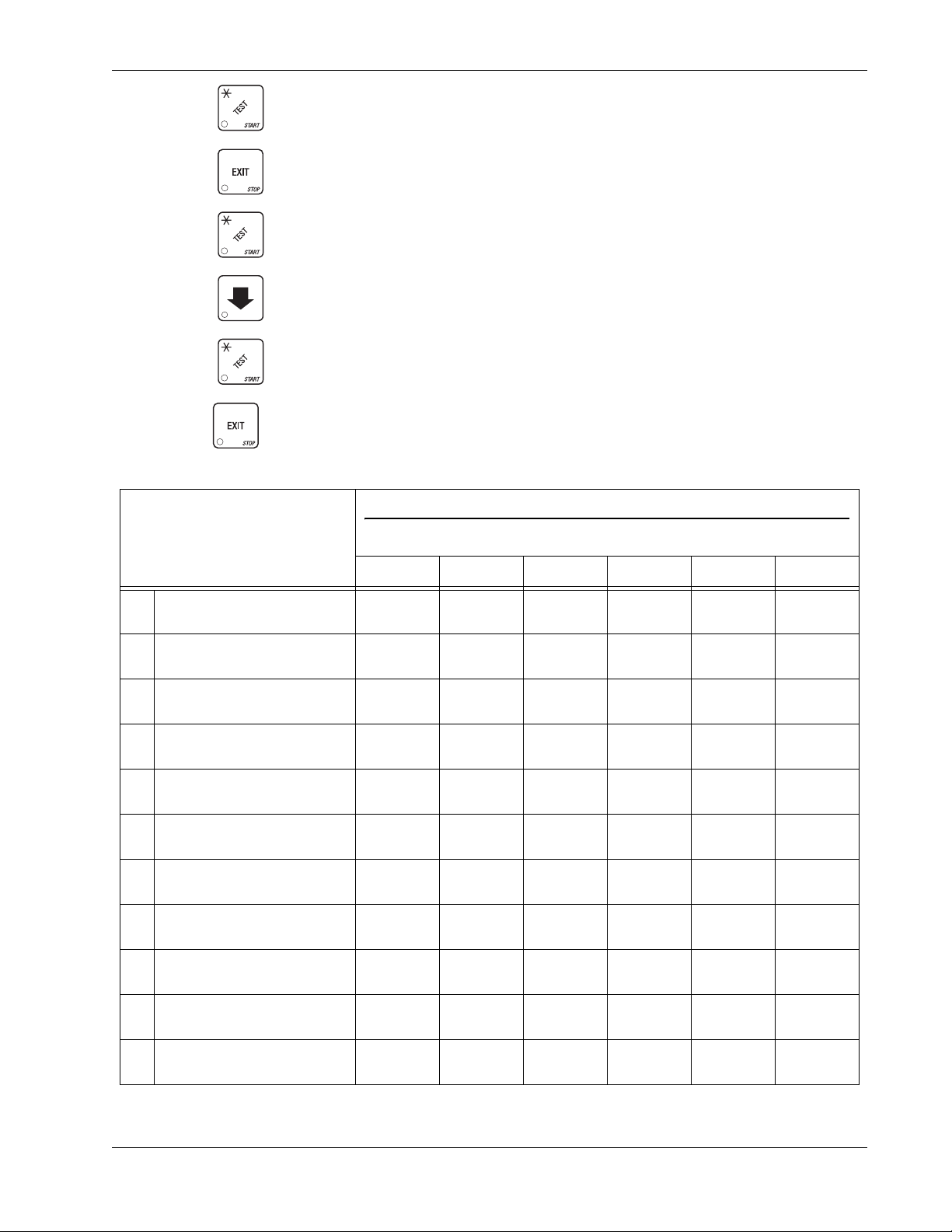
HotCup Operators’ Guide Product Configuration
k. Press . (Collect throw.)
l. Press twice.
m. Press .
n. Press to brew.
o. Press to home brewer.
p. Press .
WATER THROW DEFAULT TIMES AND VOLUMES
Selection
A Fresh brew coffee
B Fresh brew deca f
A Freeze dry coffee
B Freeze dry decaf
C 6th Product
D Espresso (FB)
D Espresso (FD)
FTea
GChocolate
H Soup
Time (in seconds) per size cup
Volume (in mL) per size cup
5oz 7oz 8oz 9oz 10oz 12oz
4.50
130
4.50
130
4.95
120
4.95
120
4.85
100
2.25
65
2.50
60
4.95
120
4.85
100
4.80
110
6.40
190
6.40
190
7.00
170
7.00
170
6.80
140
3.20
95
3.50
85
7.00
170
6.80
140
6.95
160
7.50
220
7.50
220
8.25
200
8.25
200
8.25
170
3.75
110
4.15
100
8.25
200
8.25
170
8.25
190
8.20
240
8.20
240
8.65
210
8.65
210
8.75
180
4.10
120
4.35
105
8.65
210
8.75
180
8.70
200
9.00
265
9.00
265
9.90
240
9.90
240
9.70
200
4.50
133
4.95
120
9.90
240
9.70
200
10.00
230
11.00
315
11.00
315
12.60
305
12.60
305
11.65
240
5.50
158
6.30
153
12.60
305
11.65
240
12.15
28H
H Soluble Product
November, 2007 63 6740001
4.85
100
6.80
140
8.25
170
8.75
180
9.70
200
11.65
240
Page 70
PosiVend HotCup Operators’ Guide
RINSE THE BREWER
WARNING
Very hot water will be dispensed in this te st. Coming into cont act
with hot water will HURT!
a. Press , then press until the display shows BREW RINSE.
b. Press to rinse the brewer. The brewer cycles, and RINSING is displayed.
c. CONTINUE.
FILL THE TANK
a. Press , then press until the display shows TANK.FILL.
b. Press . This clears any tank error and starts filling the tank, if necessary.
NOTE
If it is taking a long time to fill the tank AND THERE ARE NO
LEAKS, you may see TANK ERR in the diagnostic list again.
c. Just press again after making sure there are no other problems, such as a restriction
in the water inlet line or a clogged water filter.
d. CONTINUE.
PosiVend
TURN POSIVEND™ ON OR OFF
a. Press then until the display shows one of the following:
sure.v off: None of the PosiVend™ functions are available. Use this if the PosiVend™
system is not installed, or there is some reason you do not want to use it (for example in a
high cup theft situation).
sure.v on. The PosiVend™ system is operative. All of the PosiVend™ functions are
available.
b. Press to switch between the two choices.
c. Continue.
6740001 64 November, 2007
Page 71
HotCup Operators’ Guide PosiVend
OPTIONAL OR MANDATORY POSIVEND™
a. Press then until the display shows one of the following:
opt’n sure.v: The machine reverts to home switch operation of the ring motors if the
PosiVend™ system cannot operate normally because of an obstruction in the cup station or
for any other reason.
must sure.v: The vending machine is operational only if the PosiVend™ system is
determined to be working. Otherwise, the machine will go temporarily out of service until the
blockage or other error is corrected.
b. Press to switch between the two choices.
c. Continue.
SET UP THE POSIVEND™ ANTI-JACKPOT TIMER
a. Press then until the display shows
minutes PosiVend™ will be disabled for either cup ring. The same value applies to the two
timers (one on each ring).
b. Enter a number using either keypad.
If any cup ring motor fails to deliver a cup on two consecutive attempt s, the cup rin g goes out
of service. After the time set in step 2 has elapsed, the cup ring goes back in service and is
given one more chance to deliver a cup. If cup delivery is again unsuccessful, the ring goes
out of service until the machine is serviced. A successful delivery on any cup ring will reset
the failed attempts for that particular cup ring. If both cup rings perform three consecutive
failed attempts (and the PosiVend™ sensor is determined to be working), the entire machine
goes in the “mug only” mode until the machine is serviced. If either cup ring performs three
consecutive failed attempts with the other cup ring in anti-jackpot timer mode, the entire
machine will be in “mug only” mode (assuming PosiVend is working) until the preset time
elapses (one more attempt will be made to deliver a cup) or the machine is serviced by a
route operator.
c. Continue.
VIEW NUMBER OF MUG VENDS
(Not Shown If Zero)
ajp.tmr xxm. XX represents how many
a. Press , then press until the display shows
vends.
b. If desired, view this data by individual selection.
c. Continue.
November, 2007 65 6740001
MUG X. “X” is the number of mug
Page 72
PosiVend HotCup Operators’ Guide
VIEW MACHINE ID NUMBER
a. Press , then press or until the display shows
represent the 6-digit machine ID number.
b. You can edit the machine ID number if the supervisor access code has been previously
entered (See “Gain Access to the Supervisor Mode” on page 38).
c. Continue.
VIEW CUP RING CYCLES RELATED TO POSIVEND™
(Not shown if zero)
a. Press , then press until the display shows
number of vends during which more than one ring cycle was required to successfully
dispense a cup.
b. Press to clear the count.
c. Continue.
VIEW TIMES NO CUP WAS DETECTED AFTER A CUP RING CYCLED
(Not shown if zero)
PV.TOT xx. XX represents the
I.D. XXXXXX . The X’s
a. Press , then press until the display shows
number of times a cup was not detected after ring 1 cycled. Check the cup ring adjustment
(see the Operator’s Guide), or the cup stack for damage if the count is excessive.
b. Press to clear the count.
c. Press until the display shows
was not detected after ring 2 cycled. Check the cup ring adjustment (see the Operator’s
Guide), or the cup stack for damage if the count is excessive.
d. Continue.
VIEW HOME SWITCH USAGE RELATED TO POSIVEND™
(Not shown if zero)
a. Press , then press until the display shows
number of times home switches were used due to opt’n posi.v selected but not working.
b. Continue.
PV.FL2 xx. XX represents the number of times a cup
PV.FL1 xx. XX represents the
WO.PV xx. XX represents the
6740001 66 November, 2007
Page 73
HotCup Operators’ Guide PosiVend
VIEW POSIVEND™ LAST RECORDED CALIBRATION VALUE
a. Press PosiVend™ until the display shows
0 to 255, and represents the most recent value read from the sensor. The lower the number
the greater the sensor blockage. A number of 255 means that there is a fatal problem with
the PosiV end™ interface board. Ensure the PosiVend™ interface PCB is properly connected
to the main controller PCB.
b. Continue.
VIEW POSIVEND™ AVERAGE CALIBRATION VALUE
a. Press , then press until the display shows
sensor calibration value (should be between 50 and 255 for proper sensor ope ration - i.e. 51
through 254). Although this number could go as low as 20, the PosiVend™ system will be
inoperative in this condition.
b. Continue.
cal.lst xxx. XXX can be any number from
cal.ave xxx. XXX represents the average
November, 2007 67 6740001
Page 74
Pricing HotCup Operators’ Guide
Pricing
SET PRICES FOR INDIVIDUAL SELECTIONS
For this procedure, we will assume that the merchandiser is set up to vend two different sizes of
cups. Also, the machine is configured to allow customers to vend a cup only (no drink). Here is an
example of how to set prices for several different selections in this machine:
HELPFUL HINT
If most of the prices in your machine will be the same, perform the
SET ONE PRICE FOR THE ENTIRE MACHINE procedure, then
return to this procedure to set those prices which will be different.
a. Press . The display shows the maximum and minimum prices currently set in the
machine.
b. Either press to scroll through the selection list until you find the selection number you
want.
or
Go directly to the desired selection by pressing its letter.
To help you understand, here is an example. First, set the price for the regular size C
selection to $0.65. Press 0C, or until . . .
c. . . . the display shows
C .55. (The price for the C selection is currently at $0.55.) Enter the
new price (65 cents) using the number keys.
Now, set the price for the large size D selection. Press 1D, or until . . .
d. . . . the display shows
1 D.75 This is the D selection price for the large size cup (the "1"
means the large cup).
e. CONTINUE.
SET THE PRICE FOR A CUP ONLY
a. Press , then press until the display shows
2 .XX. "XX" represents the price
for a cup only.
b. Enter the new price using the number keys.
c. CONTINUE.
6740001 68 November, 2007
Page 75
HotCup Operators’ Guide Pricing
SET ONE PRICE FOR THE ENTIRE MACHINE
a. Press . The display shows ** .XX .YY. This is the maximum (XX) and minimum (YY)
prices currently set in the machine.
b. Press . The display shows **.
CAUTION
Setting all prices in the machine will currently set prices.
If you are sure you want to do this, go to the next step.
c. Enter a new price.
d. CONTINUE.
SET ONE PRICE FOR ALL REGULAR SIZE DRINKS
a. Press . The display shows ** .XX .YY. This is the maximum (XX) and minimum (YY)
prices currently set in the machine.
b. Press 0 (on the selection switch panel) and . The display shows 0*.
CAUTION
Setting these prices will currently set prices.
If you are sure you want to do this, go to the next step.
c. Enter a new price.
d. CONTINUE.
SET ONE PRICE FOR ALL LARGE SIZE DRINKS
a. Press . The display shows **
prices currently set in the machine.
b. Press 1 (on the selection switch panel) and . The display shows
Setting these prices will currently set prices. If you are sure you
want to do this, go to the next step. If not, go to step 5.
.XX .YY. This is the maximum (XX) and minimum (YY)
1*.
CAUTION
c. Enter a new price.
d. CONTINUE.
November, 2007 69 6740001
Page 76
Time Setup HotCup Operators’ Guide
Time Setup
SET THE TIME
a.Press . The display shows
TIME H.MM. "H.MM" is the time of day currently
set in the machine.
b. To change the time, just enter the time with the number keys using a 24-hour format (1300 =
1:00 pm).
NOTE
The new time will be displayed, but not updated in the system
until you press an arrow key or .
c. CONTINUE.
SET THE DAY OF THE WEEK
a.Press , then press until the display shows
@ SMTWTFS. The currently
set day of the week will be flashing. If it is correct, CONTINUE.
b. To change the day, press until the correct day is flashing.
c. CONTINUE.
SET THE DATE AND YEAR
a. Press , and press until the display shows
"
MM/DD YY" is the month, date, and year currently set in the machine. The slash (/)
MM/DD YY.
means that the U.S. date format is being used.
b. If desired, enter a new month, date, and year with the number keys.
To change to the European date format (
DD-MM YY), press . The display is now
shown with the date before the month, and the slash (/) is replaced by a dash (-) to avoid
confusion.
c. CONTINUE.
6740001 70 November, 2007
Page 77
HotCup Operators’ Guide Time Setup
SET TIME-OF-DAY INHIBITED VENDING
Vending can be inhibited up to four times a day. This is useful when you don't want the machine
used for any reason.
d. Press , then press until the display shows
e. Go to the see TIME INTERVAL EDITING procedure for an example of how to set up time-of-
day inhibited vending.
SET TIME-OF-DAY DISCOUNT VENDING
Vending can be discounted up to four times a day. For example, this can be used to favor earlyarriving employees.
a. Press , then press until the display shows
b. Go to the see TIME INTERVAL EDITING procedure for an example of how to set up Time-of-
Day Discount Vending.
SET TIME-OF-DAY FREE VENDING
Vending can be free up to four times a day.
INHIB - - - - .
DISCT - - - - . .
a. Press , then press until the display shows
b. Go to the TIME INTERVAL EDITING procedure for an example of how to set up time-of-day
free vending.
c. CONTINUE.keys to enter a new time, if desired. Range: 2.0 - 12.5 hours, in .1 hour (6
minutes) increments.
d. CONTINUE.
CUSTOM
TIME
INTERVALS
Times when normal vending is suspended in
favor of special cases. For example, coffee
could be discounted before working hours in
the morning to favor early-arriving employees.
FREEV - - - - .
November, 2007 71 6740001
Page 78
Time Setup HotCup Operators’ Guide
TIME INTERVAL EDITING
You can select up to four times of day for each special vending period.
NOTE
If two or more of these time periods overlap, the interval
with the highest priority will overrule the other(s).
This order of precedence is:
1. INHIBIT
2. FREEVEND
3. DISCOUNT
For example, if a DISCOUNT time period is scheduled before the
end of an INHIBIT time period, DISCOUNT does not begin until the
INHIBIT interval has ended.
The time interval editing procedure is almost the same for the INHIBIT, FREEVEND, and DISCOUNT
intervals. There is one difference for the DISCOUNT time interval, so that interval will be shown
here.
a. The display shows
to edit time interval 1 (we'll use interval 1 for this example).
b. The display shows
interval (represented by X) is on or off. Press to change the status of the time interval.
If you turn an interval ON, it must be edited. You can edit a time
c. Press . The display shows
period. Enter a discount percentage of 25 with the number keys.
d. Press . The display shows
Enter a new start time (24-hour format) for this interval. To enter the time for 3:30 pm, enter
1530.
e. Press . The display shows
DISCT 1234 Press the number of the time interval you want to edit, or
1.DISCT ON or 1.DISCT OFF. This display tells you whether your time
NOTE
interval now, then turn it OFF until later.
1.DSCT XX This is the discount percentage for this
1.STRT X.XX "X.XX" is the currently set start time.
1.STOP X.XX. "X.XX" is the currently entered stop time.
Enter a new stop time (24-hour format) for this interval. To enter a stop time of 6:00 pm, enter
1800. You have now established a 25% discount that starts at 3:30 pm and ends at 6:00 pm.
f. Press . The display shows
time interval is active. Pressing number keys 1 through 7 switches the days on/off. The days
you select will appear in the display. Press 2, 4, and 6. The display shows
1.@ - - - - - - -. The dashes represent the days that this
1.@ - M - W - F
-, meaning that the discount interval is only active on Monday, Wednesday, and Friday.
6740001 72 November, 2007
Page 79
HotCup Operators’ Guide Messages
g. Press . The display shows 1. - - - - - - -. The dashes represent the selections affected
by this time interval. Press the appropriate letter key to turn the selections on or off.
NOTE
Selections not vended by your machine will not be displayed.
Press A, B, F, and H. The display shows
h. Press . The display shows either:
1. MESG OFF There is no custom message selected.
or
1. MESG X. This means that custom message X (1 through 8) will be displayed during this
time interval. Press the number key of the message you want displayed. Pressing 0 turns
the message OFF for this time interval.
1. A B - - - F - H.
STAND BY
The message that is displayed during normal vending
periods when there are no out-of-service faults
(You can also press to scroll through the message list.)
NOTE
YOU CAN SET UP THE CUSTOM MESSAGE BY FOLLOWING THE
CUSTOM MESSAGE EDITING PROCEDURE.
i. CONTINUE.
Messages
SELECT A STAND-BY MESSAGE
a. Press , then press until the display shows
ST ANDBY MX. "X" represents the
current message number selected for the standby message. Two dashes mean that the
factory-set message is selected.
b. To select a message, just press the corresponding number (1 through 8). To display the
factory-set message, press 0.
OR
Press to scroll through all eight messages and the factory-set message.
c. CONTINUE.
November, 2007 73 6740001
Page 80
Messages HotCup Operators’ Guide
SELECT AN OUT-OF-SERVICE MESSAGE
a. Press , then press until the display shows
current message number selected to display when the machine is out-of-service. Two
dashes mean that the factory-set message is selected.
b. To select a message, just press the corresponding number (1 through 8). To display the
factory-set message, press 0.
OR
Press to scroll through all eight messages and the factory-set message.
c. CONTINUE.
SELECT A FREEVEND MESSAGE
a. Press , then press until the display shows
the current message number selected for the message that displays when the machine is in
the freevend mode. Two dashes mean that the factory-set message is selected.
b. To select a message, just press the corresponding number (1 through 8). To display the
factory-set message, press 0.
SERVICE XX. "XX" represents the
FREEVEND XX. "XX" represents
OR
Press to scroll through all eight messages and the factory-set message.
c. CONTINUE.
6740001 74 November, 2007
Page 81
HotCup Operators’ Guide Messages
EDIT CUSTOM MESSAGES
a. Press , and press until the display shows
the message you want to edit.
number you pressed).
b. Press . The message text is displayed with the first character flashing.
c. To view the message, press . The message scrolls across the display. To stop the
scrolling, press .
d. When the character you want to change is flashing, either enter it directly, or use and
to step through the character set until the desired character is displayed. Use the
arrow keys to highlight different characters. See the section on the next page for an
explanation of special keys and the character set.
MESSAGE X is displayed (X represents the message
EDIT MSG'S. Press the number of
SHORTCUT
Instead of stepping through the whole character set to enter a letter that is not on your
keypad, enter one close to the one you want, then step to it. Example: If you want to
enter an L, first press J on the selection switch panel.
Then press twice. Your L should now be displayed.
THE END OF MESSAGE CHARACTER
This is the most important character in your message, because it tells the machine when the
message is ended. If you don't use this character, your message will be followed by a bunch of
zeros. This character can be selected either from the character set or by a direct key entry (see the
next page).
November, 2007 75 6740001
Page 82
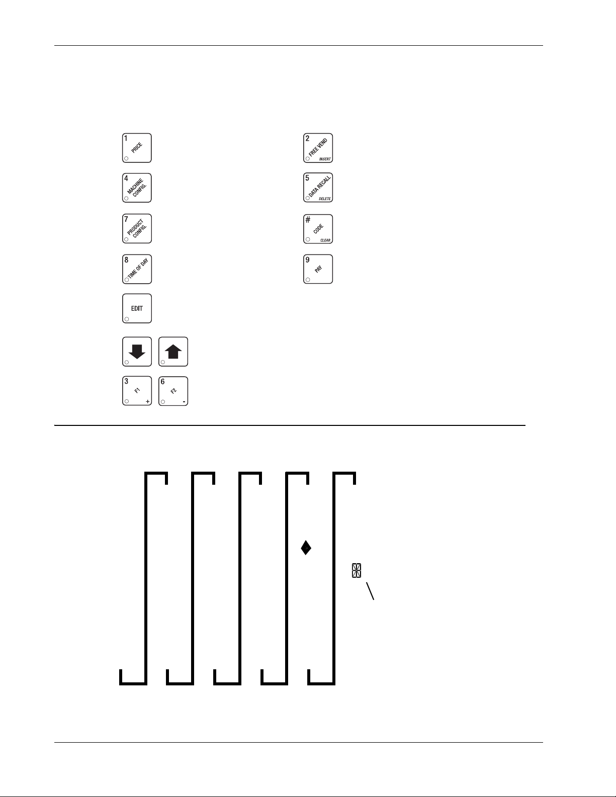
Messages HotCup Operators’ Guide
ENTERING YOUR MESSAGE
You will be using a combination of special keys and the keys on the selection switch panel to enter
your message. Pressing the keys on the selection switch panel will enter the character shown on
that key . Most of the keys on t he service keypad have a special purpose to help you create an d edit
your messages:
Inserts an R at the flashing
character.
Inserts an S at the flashing
character.
Inserts a T at the flashing
character.
Repeats the letter to the left
of the flashing character.
"Pages" through the
message, ten characters
(one screen) at a time.
Steps forward and backward through the message, one
character at a time.
Steps forward and backward through the character list,
one character at a time.
Inserts a space at the
flashing character.
Deletes the current
character and closes up the
space.
Deletes the current
character and leaves the
space.
Enters the special "end of
message" character, which
denotes the end of the
message.
THE CHARACTER SET
0Aku[ >
1blv]?
2cmw# @
3dnx °
4eoy+
5fpz-
6gq (Space)/
7hr-.
8i s$<
9jt‘ =
THIS IS THE END OF
MESSAGE CHARACTER.
6740001 76 November, 2007
Page 83
HotCup Operators’ Guide Testing
TEST VEND SELECTIONS AND VERIFY CREDIT ADDED
Testin g
a. Press . The display shows TEST .00. You may now test vend selections.
b. To test vend selections without dropping a cup, press . The display shows
.00
. No cups will drop during the rest of your test vend session. If desired, you may place
TEST.NC
money in the machine.
In either case, if you insert money into the machine, the zeros in the display will be replaced
with the amount of the credit.
NOTE
Y ou may make one more test v end if you close the door while still
in TEST VEND mode.
c. CONTINUE.
TEST THE DISPLAY
a. Press , then press until the display shows
DSPLY TEST.
b. Press to light all display segments light; press to turn them off.
c. Pressing a number key on the maintenance keyp ad, or any key on the selection switch p anel
causes all segments to display that character.
NOTE
To help differentiate the two keypads, a number from the
maintenance keypad has an apostrophe after it:
from the selection switch panel has a period after it:
d. CONTINUE.
TEST THE CUP MECHANISM
a. Press , then press until the display shows
b. You can test the cup mechanism one of several ways:
Press 1 or . A cup is dispensed from the cup ring.
c. CONTINUE.
1 '. A number
1..
CUP TEST.
November, 2007 77 6740001
Page 84
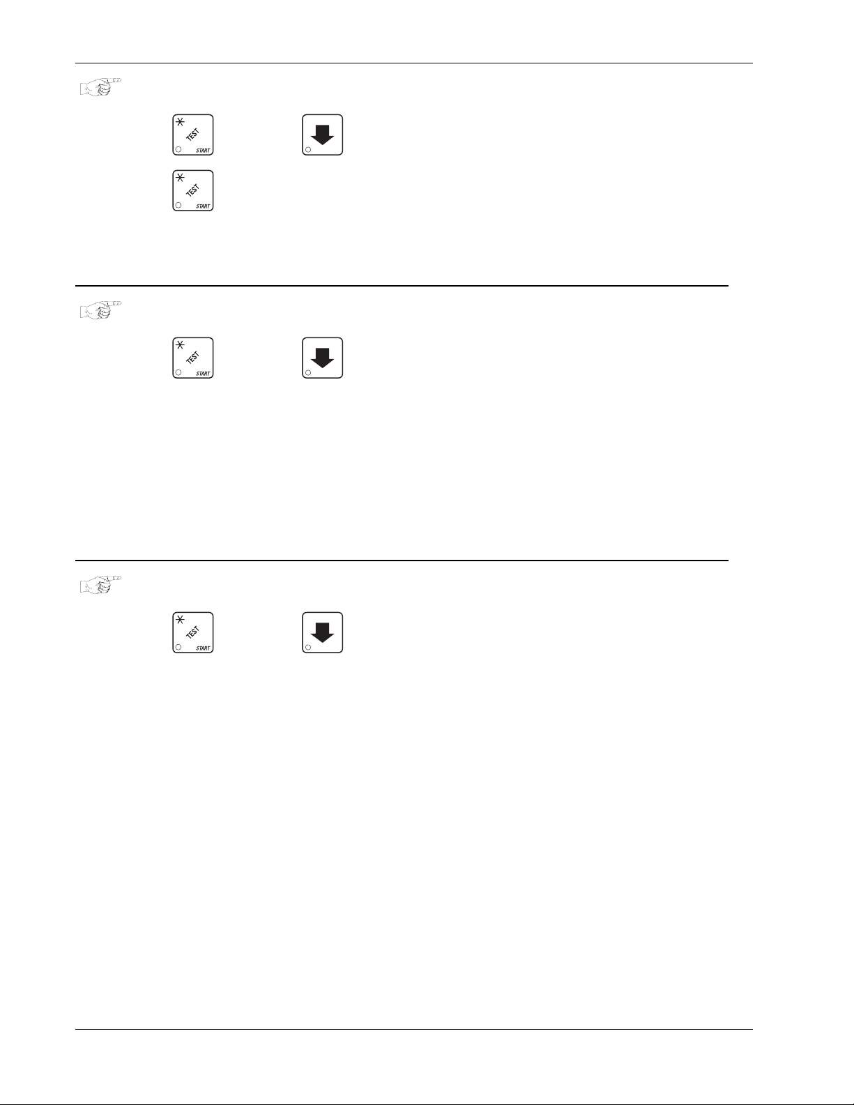
Testing HotCup Operators’ Guide
TEST THE AUTOMATIC DOOR (OPTIONAL)
a. Press , then press until the display shows
b. Press to test the automatic delivery door. The door will open, then close after one
second.
c. CONTINUE.
TEST THE WHIPPERS
a. Press , then press until the display shows
b. Press the whipper number (1=whipper below main condiment mixing bowl, 2=soup whipper,
or 3=chocolate whipper) you want to test.
OR
Press the letter of a selection containing a whipper.
In either case,
c. CONTINUE.
WHIP X is displayed while the whipper under test ("X") runs.
DOOR TEST.
WHIP TEST.
TEST THE PUMP
a. Press , then press until the display shows
b. Press to test the pump.
c. CONTINUE.
AIR TEST.
6740001 78 November, 2007
Page 85
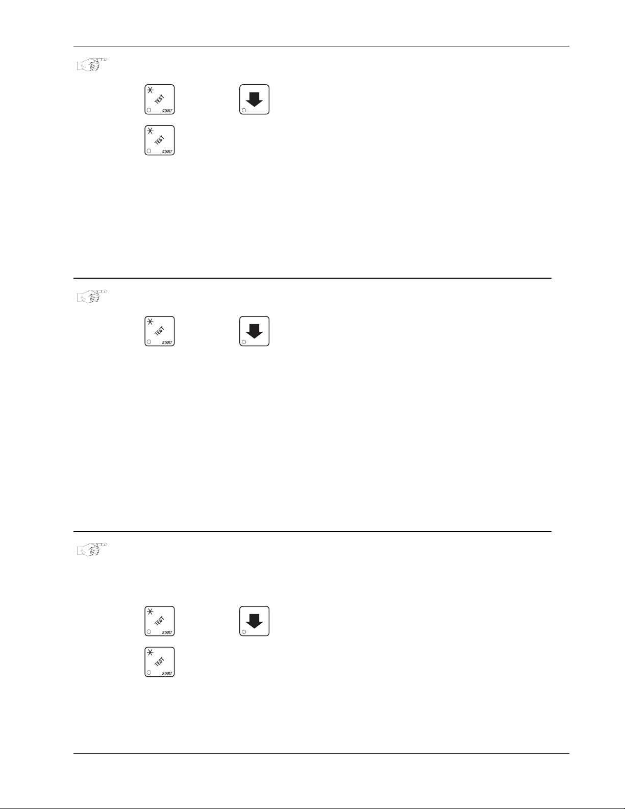
HotCup Operators’ Guide Testing
TEST THE BREWER
a. Press , then press until the display shows
b. Press to test each brewer position:
WARNING
Keep away from the brewer mechanism while it is operating.
Coming into contact with moving parts could injure you.
BREW CLMPD The brewer is in the brew position.
i.
ii.
BREW HOME The brewer is in the HOME position.
c. CONTINUE.
TEST VARIOUS SENSORS AND SWITCHES
a. Press , then press until the display shows
display will be replaced by the following place holders: M K P H L 1, defined as follows:
M = mug/cup sensor (if equipped) K = freevend keyswitch
P = waste pail switch H = high water tank level switch
BREW TEST.
IN.XXXXXX. The X's in the
L = low water tank level switch 1/2 = ring 1/2 cup sensor switch
b. Actuate each switch or sensor to test its function. As you actuate each input, the display
element representing that switch blinks on. Releasing the switch causes that element to blink
off again, and be replaced by a dash.
c. CONTINUE.
RINSE ALL MIXING BOWLS
WARNING
Very hot water will be dispensed in this test. Coming into cont act
with hot water is dangerous!
a. Press , then press until the display shows
b. Press to rinse all bowls.
c. CONTINUE.
RINSING is displayed.
BOWL RINSE.
November, 2007 79 6740001
Page 86
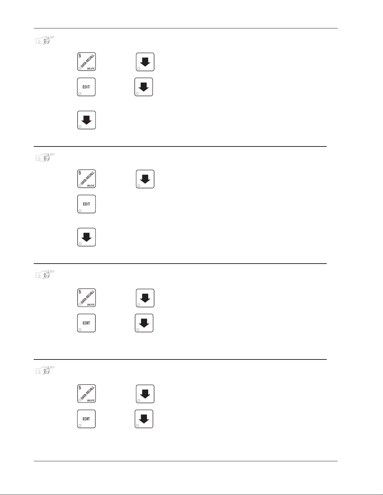
View Machine Info HotCup Operators’ Guide
View Machine Info
VIEW FREEVEND SALES BY TIME INTERVAL
(not shown if zero)
a. Press , then press until the display shows
b. Press , then press until the display shows 1.FRV .00. This is the total sales for
freevend interval 1, shown even if zero.
c. Press to view intervals 2 through 4.
d. CONTINUE.
VIEW DISCOUNT SALES BY TIME INTERVAL
a. Press , then press until the display shows **
b. Press . The display shows
(not shown if zero).
c. Press to view intervals 2 through 4.
1.DSC .00. This is the total sales for discount interval 1
_0$ XX.XX.
$ XX.XX.
d. CONTINUE.
VIEW FREE VENDS
(not shown if zero)
a. Press , then press until the display shows
b. Press , then press until the display shows
machine-wide freevends, shown even if zero.
c. CONTINUE.
VIEW WINNERS
(not shown if zero)
a. Press , then press until the display shows
b. Press , then press until the display shows
machine-wide winners, shown even if zero.
_0$ XX.XX.
FRV XX.XX. "XX.XX" is the tot al
_0$ XX.XX.
WIN XX.XX. "XX.XX" is the total
c. CONTINUE.
6740001 80 November, 2007
Page 87
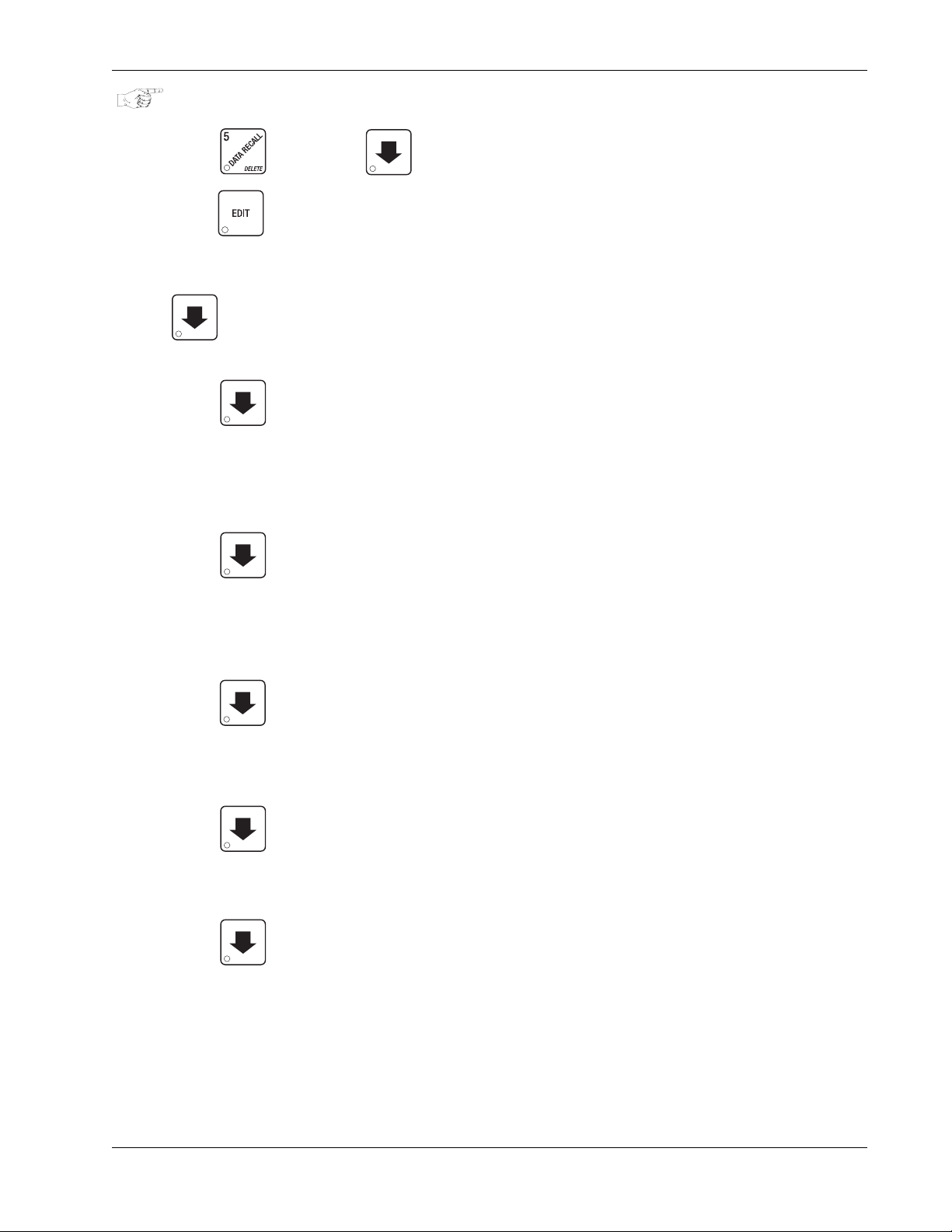
HotCup Operators’ Guide View Machine Info
VIEW TIME DATA
a. Press , then press until the display shows
b. Press . The following message scrolls across the display: MAIN.1 237M 01/30 10.13
This example shows the latest time interval the main (machine) door was open (1). It was
open for 237 minutes, and was opened on January 30 (01/30) at 10:13 am (10.13). Press
. If applicable, similar displays will appear for intervals 2, 3, and 4, otherwise, go to the
next step.
c. Press . The following message scrolls across the display:
TIME DATA.
LAST POWER 01/30 13.51 FOR 00. 0.23
This example shows that the last time the machine lost power was on January 30 (01/30) at
1:51pm (13.51) for zero days, zero hours, and 23 minutes (00. 0.23).
d. Press . The following message scrolls across the display:
LONGS.T POWER 01/30 10.58 FOR 00. 2.47
This example shows that the longest time the machine was without power was on January 30
(01/30) at 10:58am (10.58) for zero days, 2 hours and 47 minutes (00. 2.47).
e. Press . The following message scrolls across the display:
This example shows that the last time resettable sales was fully cleared was on January 30
(01/30) at 8:58am (8.58).
f. Press . The following message scrolls across the display:
This example shows that the last time the time or date was set was on January 30 (01/30) a t
9:15 am (9.15).
g. Press . The following message scrolls across the display:
This example shows that the last time prices were set was on January 30 (01/30) at 9:42 am
(9.42).
h. CONTINUE.
NOTE
Refer to (VIEW DATA THREE DIFFERENT W AYS, page 83) to view
the date and time of the last vend of that selection.
FULL CLEAR 01/30 8.58
TIME SET 01/30 9.15
PRICE SET 01/30 9.42
November, 2007 81 6740001
Page 88
View Machine Info HotCup Operators’ Guide
VIEW TOTAL UNPAID SALES
NOTE
This does not appear if the total of unpaid sales is zero.
a. Press , then press until the display shows
unpaid sales (free vends, winner vends, 100% discounts, zero price vends) for the entire
machine.
b. If desired, view this data by tray and individual selection.
c. CONTINUE.
VIEW TOTAL UNPAID VENDS
a. Press , then press until the display shows
unpaid vends for the entire machine.
b. If desired, view this data by tray and individual selection.
c. CONTINUE.
VIEW NUMBER OF TEST VENDS
(not shown if zero)
_0$ XX.XX. "XX.XX" is the total
_0 XX. "XX" is the total number of
a. Press , then press until the display shows
vends.
b. If desired, view this data by cup size and individual selection.
c. CONTINUE.
VIEW SALES DATA BY PRICE
You can view the total sales of each separate price in the machine.
a. Press , then press until the display shows **
b. Press . The display shows the lowest price followed by the dollar sales of all
selections costing that price.
c. Press to step through all the prices set in the machine.
TST X. "X" is the number of test
$ XX.XX.
d. CONTINUE.
6740001 82 November, 2007
Page 89
HotCup Operators’ Guide View Machine Info
SET FREEVEND OPTIONS
a. Press until one of the following is displayed:
FREE OFF - Normal vending mode. No items are on freevend. A closure on the keyswitch
input causes the machine to go out of service.
OR
FREE ALL - All items are on freevend. The credit display shows NO MONEY REQUIRED
A closure on the keyswitch causes the machine to go out of service.
OR
FREE W/KEY - All items are freevended while there is a closure on the keyswitch input.
Normal cash sales are supported when the keyswitch input is open. If the free vend code
(selected under SUPERVISOR MODE) is not 0000, the code must be entered first.
OR
FREE ONCE - A closure on the keyswitch input causes only the next item to be freevended.
Coin mechanism errors are ignored. This state is designed for card or token systems where
one item is vended per token. Normal cash sales are also supported.
b. Press until the option you want is displayed.
c. CONTINUE.
VIEW MACHINE ID NUMBER
a. Press , then press until the display shows
the 6-digit machine ID number.
b. CONTINUE.
VIEW NON-RESETTABLE SALES AND VEND DATA
a. Press . The display shows
showing the total of all sales in the machine. This is a running total, and is not resettable.
b. Press . The display shows
NR$ XX.XX. "XX.XX" is a dollar and cents figure
NR X. "X" is the total number of vends made by the
I.D. XXXXXX . The X's represent
machine. This is a running total, and is not resettable.
c. CONTINUE.
November, 2007 83 6740001
Page 90
View Machine Info HotCup Operators’ Guide
VIEW DATA THREE DIFFERENT WAYS
Paid sales and vends can be viewed three different ways: By whole machine, by selection type, a nd
by individual selection. The first screen of the data item shows its machine total.
i. To view the data by selection type, press the letter of the type you want to see. For
example, pressing A shows you the total sales and vends for the combined regular and
large size cups of the A selection. You can then press and to see data for
all the active selection types.
ii. To view the data by individual selection, press the letter and number of the selection you
want to see. You can then press and to see data for all the active
selections.
iii. If viewing data by individual selection, press to view the date and time of the last
vend of that selection.
VIEW TOTAL PAID SALES
a. Press , then press until the display shows **
and cents figure showing the total of all PAID sales in the machine (as opposed to unpaid
sales like winner and free vends). This is the total since the last time it was cleared.
b. If desired, view this data by cup size and individual selection.
c. Continue.
VIEW CARD READER PAID SALES
(not shown if zero)
a. Press , then press until the display shows **
b. Press . The display shows DBT XX.XX. "XX.XX" is the amount of money collected
from card reader sales.
c. CONTINUE
$ XX.XX. "XX.XX" is a dollar
$ XX.XX.
6740001 84 November, 2007
Page 91
HotCup Operators’ Guide View Machine Info
VIEW TOTAL PAID VENDS
a. Press , then press until the display shows **
paid vends for the entire machine.
b. If desired, view this data by cup size and individual selection.
c. CONTINUE.
CLEAR ALL RESETTABLE DATA
a. Press . The display shows
resettable.
b. Press and hold . Tw o beeps sound and the display shows
and then changes to
c. CONTINUE.
CLEAR PAID SALES DATA ONLY
FINISHED. All data is cleared.
NR$ XX.XX. This is a running total, and is not
XX. "XX" is the total number of
CLEARING momentarily,
a. Press , then press until the display shows **
and cents figure showing the total of all PAID sales in the machine (as opposed to unpaid
sales like winner and free vends). This is the total since the last time it was cleared.
b. Press and hold . Tw o beeps sound and the display shows
and then changes to
c. CONTINUE.
VIEW AMOUNT IN COIN BOX
(not shown if zero)
a. Press , then press until the display shows
XX.XX" is the dollar and cents amount in the coin box.
"
b. CONTINUE.
FINISHED. All paid sales data is cleared; other data is not cleared.
$ XX.XX. "XX.XX" is a dollar
CLEARING momentarily,
CBX XX.XX.
November, 2007 85 6740001
Page 92
View Machine Info HotCup Operators’ Guide
VIEW AMOUNT IN VALIDATOR
(not shown if zero)
a. Press , then press until the display shows
XX.XX" is the dollar amount in the bill stacker.
"
b. Press to show the quantities of bills in the stacker. For example, the display shows
DBV XX.XX.
$0120, meaning that there are 20 dollar bills in the bill stacker. Press again to show
the quantities of other bills, such as $5s, $10s, or $20s.
c. CONTINUE.
VIEW DIAGNOSTIC MESSAGES
a. Press . The display shows any of the following diagnostic messages, depending upon
any fault(s) present:
NO ERRORS None of the following errors are detected:
KEYPAD xy Key(s) x, y stuck.
ROM ERROR Key(s) x, y stuck.
RAM ERROR RAM is not initialized or is not compatible with the currently loaded
software. If this message appears, initialize your RAM by
performing the following procedure:
NOTE:
Initializing RAM will erase all your data and drink settings. Be
sure you have written this information down before continuing.
b. Press and hold until two beeps are heard, and the display shows
FINISHED.
6740001 86 November, 2007
Page 93

HotCup Operators’ Guide View Machine Info
KEYSWITCH
MACH.TYPE 0
D+J+WXYZ
TANK ERR
RING 1, 2
MTR 1A1B2X
NO CUPS 1, 2
BREW JAM
WASTE PAIL
LOW WATER
The keyswitch input is active and configured as an inhibit.
Machine type error displays machine type screen. NOTE: This is the
actual machine type screen. You may enter the correct machine type
number directly on this screen without further action.
Configuration error; displays the machine configuration screen. NOTE: this
is the actual config screen. You may enter the correct config number
directly on this screen without further action.(Verify cup size and product
times in the product configuration screen).
Tank failed to fill or refill.
The cup ring is jammed.
Cup turrets are jammed.
Out of cups.
The brewer is jammed.
The waste pail is full.
The water level in the tank is low.
COLD WATER
NO SENSOR
No float
WHIP 1 2 3 4 5
DOOR JAM
NO MECH
MECH COMM
MECH.SENSOR
MECH ROM
MECH.ACCEPT
MECH JAM
DEBIT CARD
Water in the tank is too cold to vend.
Temperature sensor failed or missing.
Float sensor failed or missing.
Whipper motor failure (motor 1, 2, 3, 4, 5)
The automatic delivery door is jammed.
Coin mech not detected - machine will not operate if configured for coin
mech
Incomplete coin mech communications check harness.
Coin mech reporting a bad tube sensor replace mech.
Replace the coin mechanism.
Coin mechanism acceptor section is unplugged from the main body of the
coin mech. Connect the cable and cycle machine power OFF and then ON.
One or more coin tubes are jammed. Pay a coin from each tube until the
jam is cleared.
Card reader reporting error — machine will not operate if configured for
DEBIT ONLY.
CHECK DBV
November, 2007 87 6740001
Bill validator reporting error — machine will not operate. Empty stacker,
clear jams, etc.
Page 94

View Machine Info HotCup Operators’ Guide
DBV COMM
DBV MOTOR
DBV SENSOR
DBV JAM
DBV STACKR
CHK PRICE
NONE READY
pV.ERR CUP 1
pV.ERR CUP 2
Incomplete bill validator communications — check harness.
One of the motors has failed. The unit will disable itself until the error is
corrected. Check for bill stuck in the acceptance path. If no bill is present,
replace the validator. Cycle machine power OFF and then ON.
One of the sensors in the bill validator has failed. The unit will disable itself
until the error is corrected. Check for bill stuck in the acceptance path. If no
bill is present, replace the validator. Cycle machine power OFF and then
ON.
A bill is jammed in the acceptance path. The unit will disable itself until the
error is corrected. Remove bill stuck in the acceptance path. Cycle
machine power OFF and then ON.
The stacker is open or removed. The unit will disable itself until the error is
corrected. Install the stacker correctly.
Price error detected and changed to maximum - check prices.
All selections are reported out of service.
Cup ring 1 is out of service due to a PosiVend™ error.
Cup ring 2 is out of service due to a PosiVend™ error.
pV.ERR PCB
PV.ERR SNSR
AJP.TMR1 XX
JP.TMR2 XX
ANo brewer
Brewer.err
Brewer jam
Reset brwr
PosiVend™ is ON but not working. The last calibration sample was 255.
Check that the PosiVend™ PCB is present at J34.
PosiVend™ is ON but not working. The last calibration sample was £50.
Check for a blocked sensor or disconnected harness.
PosiVend™ is active and ring 1 anti-jackpot timer is ON. XX is a value
between 1 and 99 in minutes.
PosiVend™ is active and ring 2 anti-jackpot timer is ON. XX is a value
between 1 and 99 in minutes, and represents the amou nt of time le f t on the
anti-jackpot timer for this cup ring.
Brewer is missing or malfunctioning.
The brewer is in an incorrect position.
The brewer has not reached an appropriate position within a certain time-
out period. Check for a physical jam or a motor stall condition.
The brewer is clamped and not vending, or is not in a brewer test mode.
Close the door (if open), or run a brew test.
6740001 88 November, 2007
Page 95
HotCup Operators’ Guide View Machine Info
DOWNLOAD DATA TO A PDCD
a. Connect your portable data collection device (PDCD) in accordance with its operating
instructions.
b. Press . Data is downloaded into your PDCD.
NOTE
Depending upon the setting selected (See “Set Printer or Dex Options”
on page 40), data may be cleared after the download is complete.
c. Continue.
CHANGE MACHINE ID NUMBER
a. Follow the steps in (See “Gain Access to the Supervisor Mode” on page 38).
b. Press , then until the display shows
digit machine ID number.
c. Using the number keys, enter a new ID number.
d. CONTINUE.
VIEW THE WATER TANK TEMPERATURE
a. Press . The display shows
(in degrees F or C, depending upon your choices).
b. CONTINUE.
VIEW THE CURRENT SOFTWARE VERSION NUMBER
a. Press , then press until the display shows
software version number.
TEMP XX F. This is the current water tank temperature
I.D. XXXXXX . The X's represent the 6-
VER XXXX. This is the current
b. CONTINUE.
VIEW THE SELECTION MACHINE TYPE
a. Press then until the display shows
(See “Set the Machine Type Configuration Code” on page 55).
b. CONTINUE.
November, 2007 89 6740001
MACH.TYPE (X). This is machine type,
Page 96
View Machine Info HotCup Operators’ Guide
VIEW THE SELECTION MACHINE TYPE CONFIGURATION
a. Press , then press until the display shows
type configuration. (See “Product Configuration” on page 57) for an explanation of "W", "X",
"Y", and "Z".
b. CONTINUE.
VIEW THE SELECTION CONFIGURATION
a. Press , then press until the display shows
selections are available for sale and setup for regular size drinks. If one or more of the letters
in the display are replaced by dashes (-), that selection is unavailable.
b. Press . The display shows
available for sale and setup for large size drinks. If one or more of the letters in the display
are replaced by dashes (-), that selection is unavailable.
c. CONTINUE.
1.ABCDEFGH. This shows which selections are
CONF WXYZ. This is the machine
0.ABCDEFGH. This shows which
6740001 90 November, 2007
Page 97

HotCup Operators’ Guide Sanitation
Sanitation
BASICS
INTRODUCTION
Anybody who services vending machines must use proper sanitizing procedures. Health regulations
require that hands be clean when cups, commodities, and food-contact parts are handled or
serviced.
In addition, Federal and State Health Departments require regular cleaning and sanitizing
procedures for food contact parts.
The information in this section will explain how to clean and sanitize the merchandiser on a day to
day basis. A clean and well maintained merchandiser will provide a better product and greater safety
for your customers.
CLEANING AND SANITIZING -- WHAT’S THE DIFFERENCE?
Clean means “free of visible soil”. In cup vending machine servicing, cleaning is also done to
maintain product quality and to remove food soils, oils, and mineral stains that could affect product
taste, aroma, and appearance.
Sanitizing means the reduction, to safe levels, of the number of disease-causing bacteria that remain
on the surface after cleaning. Therefore, cleaning and sanitizing are done in separate steps, as
prescribed by health regulations and good industry practice.
When you sanitize you create a healthy and hygienic condition. This leads to wholesome food,
which in turn leads to satisfied customers.
SANITIZING IS NO SUBSTITUTE FOR A GOOD CLEANING
HOW DO I SANITIZE?
You can sanitize by using either of these two methods:
Chemicals: The object to be sanitized is treated with a bactericidal compound.
Heat: Raise the temperature of the object high enough to kill bacteria. Water must be at
least 170° F.
Hot brew water (if available) is an acceptable sanitizer
washed and/or rinsed, use the hot water available in the machine.
Turn the machine off before using water on the machine.
. When food contact surfaces are
In either case, the object must be thoroughly clean and completely rinsed in order for the sanitizing
process to work. Caked-on soils not removed by cleaning, for example, may shield bacteria from a
sanitizing solution.
November, 2007 91 6740001
Page 98

Sanitation HotCup Operators’ Guide
A GOOD PLACE TO START -- YOUR SANITATION KIT
You need to be sure that each machine is clean, safe, and functioning when you leave it. In order to
properly do this, you need to have a complete set of the right tools. In addition to the screwdrivers,
pliers, and test equipment necessary to repair a machine, you need to have the tools to clean the
machine.
Here is a checklist of the items needed for a good sanitation kit:
• Sanitation pail
• Tube and nozzle brushes for food contact surfaces
• Utility brush for dry spillage around canisters, etc.
• Disposable towels, wet-strength and lint-free
NOTE
Wiping with towels can re-contaminate sanitized food-contact
parts. Therefore, towels should not be used to dry food-contact
surfaces. Instead, these parts should be air dried.
• Spray detergent, diluted to desired strength
• Urn cleaner packets for coffee stains and oils
• Odor control chemicals for pails
• Replacement parts (if the exchange method is used)
• Cabinet polish or window cleaner for the outside of the machine
Feel free to add some items to this list. For example, you may want to use a portable vacuum
cleaner.
SANITATION PROCEDURES
Refer to the recommended cleaning and sanitation interval table on the final p age of this section. For
each item, complete the procedure as outlined here.
Food-Contact Parts
NOTE
All food-contact parts must be cleaned and sanitized.
Air dry, do not wipe dry.
Ingredient Canisters
water and allow to air dry completely before returning to cabinet.
Mixing Bowls
operation as outlined in the Programming section of this manual.
If needed, remove mixing bowls from the dry ingredient shelf. W ash the mixing bowl lids and
sanitize with hot water. Allow to completely air dry before reassembling.
Whipper Lids and Impellers
lids and impeller housing. Sanitize with hot water and allow to air dry before reassembling.
- The inside of all mixing bowls can be rinsed by performing the “Bowl Rinse”
- Empty and wash the canisters, augers, and spouts. Sanitize with hot
- Remove lids and impellers from the whipper housings, wash the
Beverage Discharge Nozzles
Remove the nozzles from the mounting bracket. Remove the cap from the nozzle, wash
clean and sanitize the nozzles and cap. Refer to the tubing connection diagram for proper
routing.
6740001 92 November, 2007
- Disconnect the beverage dispensing tube from the nozzles.
Page 99
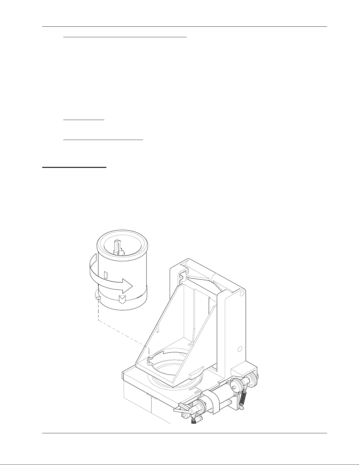
HotCup Operators’ Guide Sanitation
Brewer, Brewer Basket, and Brewer Funnel - The tubing and brewer may be sanitized by
performing the BREW RINSE operation as outlined in the programming section. The
machine features an automatic brewer sanitizing feature also described in the programming
section.
At times, it may be necessary to wash and sanitize the individual brewer parts. If so,
disconnect the tubes from the brewer manifold. Remove the brewer barrel and manifold ass
embly from its support. Remove the brewer basket and funnel assemblies.
Thoroughly wash all parts using soap and water. Sanitize by rinsing thoroughly with hot
water.
Coffee Chutes
water. Air dry before reinstalling.
Condiment Chute Assembly
canisters. Thoroughly wash all parts using soap and water. Sanitize by rinsing thoroughly
with hot water.
BREWER CLEANING
The brewer has two main parts you can remove: the brew barrel and the funnel screen and seal assembly. You
can remove them with the brewer in the machine, or the entire brewer can be removed as one unit.
a. On the left side of the brewer, cut off and discard the filter paper (not required for paperless).
b. Grasp the top of the brew barrel, and turn it counter-clockwise ¼ turn to the right as shown. Lift
straight up and remove
- Remove the metal chute(s), wash clean, and sanitize by rinsing with hot
- Remove the condiment chute and cover from the condiment
November, 2007 93 6740001
Page 100
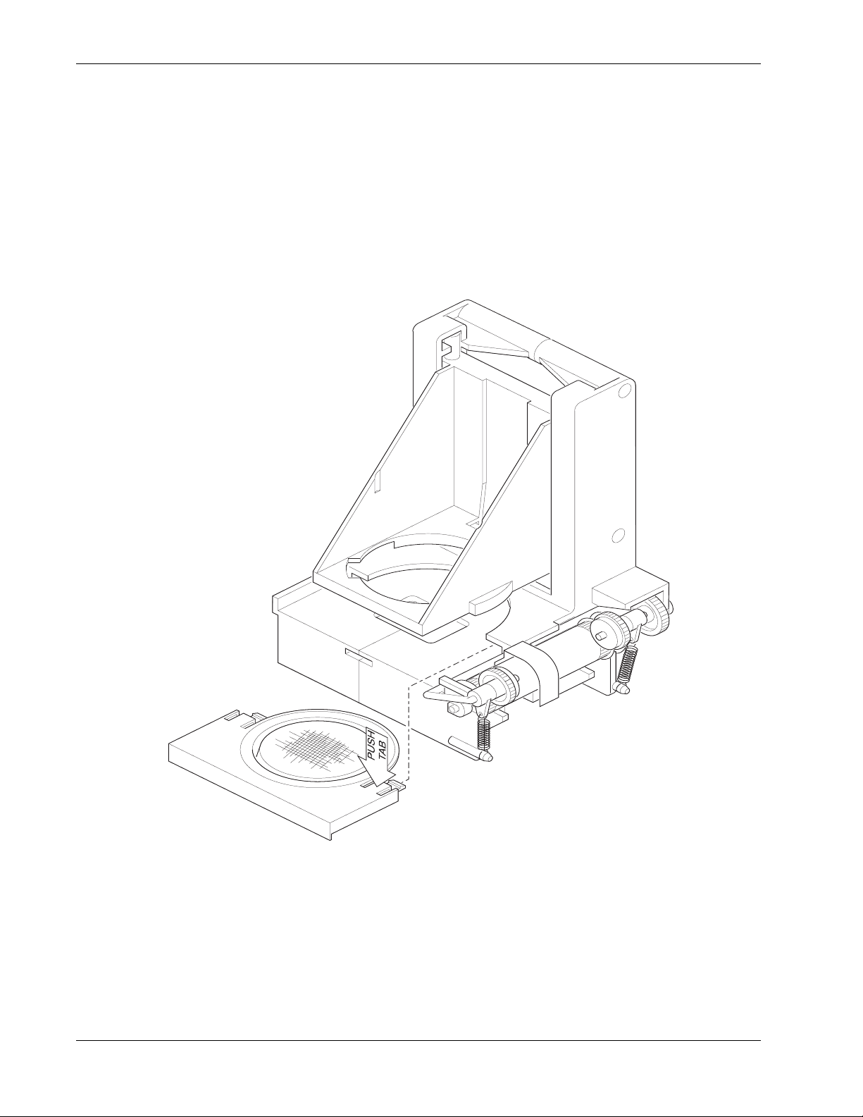
Sanitation HotCup Operators’ Guide
c. Remove the hose from the bottom of the funnel screen and seal assembly.
d. At this point, you can remove the brewer or leave it in the machine.
e. To remove the brewer, tilt the latch down and swivel the brewer up and out.
f. Remove the screen and seal assembly as shown:
• Press down on the tabs with your fingers, and slide straight back.
•Lift straight up and pull out.
Brewer Assembly w/ Paper
6740001 94 November, 2007
 Loading...