


OSAI - PLC
OSAI - PLC

Osai - PLC
VERSION |
DATE |
DESCRIPTION OF REVISION |
DRAWN UP BY |
CHECKED BY |
00.00 |
12/09/13 |
FIRST DOCUMENT DRAFT |
MAGRI MARCELLO |
|
01.00 |
30/10/13 |
PROCEDURE REVISION BCK/RST |
FAUSTO ZANARDI |
LORIS VALSECCHI |
|
|
|
|
|
|
|
|
|
|
|
|
|
|
|
|
|
|
|
|
|
|
|
|
|
|
|
|
|
|
|
|
|
|
|
|
|
|
|
|
|
|
|
|
|
|
|
|
|
|
|
|
|
|
|
|
|
|
|
|
CFP0110001/01 - 2 -

Osai - PLC
TABLE OF CONTENTS |
|
Introduction........................................................................................................................... |
4 |
Purpose of document.............................................................................................................. |
4 |
Description of Automation Project Parts.................................................................................... |
4 |
CNC functions and PLC functions ............................................................................................. |
5 |
NC – PLC interaction............................................................................................................... |
5 |
SW structure of the NC ........................................................................................................... |
6 |
AMP ...................................................................................................................................... |
7 |
Applications by Machining Centre Manufacturer......................................................................... |
7 |
WIN folder............................................................................................................................. |
8 |
PLC Structure......................................................................................................................... |
9 |
Variable Nomenclature.......................................................................................................... |
10 |
TABLES OF SYMBOLS FOR I/O SIGNAL NOMENCLATURE......................................................... |
10 |
TABLE OF SYMBOLS FOR GLOBAL VARIABLE NOMENCLATURE................................................. |
11 |
TABLE OF SYMBOLS FOR GLOBAL VARIABLE NOMENCLATURE (Volatile only) ........................... |
12 |
NOTES AND EXAMPLES......................................................................................................... |
13 |
TABELLA DEI SIMBOLI PER NOMENCLATURA ULTERIORI STRUTTURE DATI............................. |
14 |
Debug PLC........................................................................................................................... |
15 |
Ricerche Veloci..................................................................................................................... |
17 |
ulteriori operazioni di debug .................................................................................................. |
17 |
Backup & Restore CN............................................................................................................ |
18 |
Backup CN........................................................................................................................... |
18 |
Restore CN .......................................................................................................................... |
23 |
Riferimenti........................................................................................................................... |
27 |
CFP0110001/01 - 3 -
Osai - PLC
INTRODUCTION
PURPOSE OF DOCUMENT
This document is meant for assistance support; therefore its aim is simplifying and speeding up the diagnosis of any machining centre troubles.
For this purpose the following topics will be dealt with:
-Description of the main parts of OSAI automation project
-Description of the CNC and PLC basic structures and related interactions
-Description of PLC Debug operations
-Description of NC OSAI Backup and Restore operations
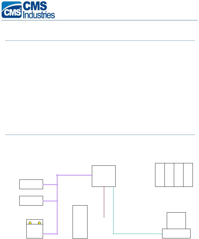
DESCRIPTION OF AUTOMATION PROJECT PARTS
The figure below displays the components of a typical NC OSAI Automation project
|
|
|
CNC |
|
AXES DRIVES |
|
|
|
|
|
|
Peripherals |
canbus |
|
mechatrolink |
|
|
|
|
||||
|
|
||||
|
|
|
|
|
|
|
|
|
|
|
|
|
|
|
|
|
|
|
|
|
|
|
|
|
|
|
|
|
|
|
PC |
|
|
|
|
|
|
||||
|
|
|
|
serial |
|
OFFICE |
||
|
|
|
|
ethernet |
|
|
||
|
|
|
|
|
|
|
||
|
|
|
|
|
|
|
||
|
|
|
|
|
|
|
||
|
|
|
|
|
||||
|
|
|
|
|
|
|
|
|
INVERTER
CFP0110001/01 - 4 -

Osai - PLC
CNC FUNCTIONS AND PLC FUNCTIONS
The main component of the automation project is the CNC (Computer Numerical Control (referred to as NC from now onwards)) which carries out the following functions:
a)Part-Program interpretation and execution
b)Interpolation and axis handling control
c)Management of Process Variables (E, @, L()…)
d)System parameterization
In particular, the NC OSAI integrates also the PLC (Programmable Logic Controller) of the machining centre. The PLC consists of a program written in a programming language called WinPLUS which, once compiled and transferred into the NC memory, is run by the CPU of the NC cyclically.
The PLC carries out the following tasks:
a)Manages the “Machine interface logic” , that is, manages all the Inputs/Outputs (digital/analog, local/remote) of the machine.
b)Informs the machining centre operator about any anomalies, detected via screen messages or warning lights; attends to stop the machining centre functions temporarily or definitively based on the seriousness of such anomalies.
c)Enables the workpiece machining process to progress (Part-Program) and checks that at the beginning and end of each programmed block all necessary conditions exist to be able to carry on machining.
d)Manages the requests made by the Part-Program via the M,S,T auxiliary functions.
e)Manages the requests made by the machining centre operator:
o selects the operation mode of NC (AUTOMATIC, MDI, JOG, HOMING …) o starts, stops and resets the machining process
omanages the requests made via Softkey available on the PC OFFICE.
f)Manages the various automatic cycles so that they run concurrently with the machining process.
g)Acquires process variable values and axis dimensions, checks axis-axis or axis-machine frame collisions.
NC – PLC INTERACTION
DIRECT INTERACTON
The NC retentive memory houses a memory area called VARIABILI PLUS which you can access both from PLC and NC (from Part-Program or by accessing the related variable list). This memory are is provided with 256 full format variables (subdivided into boolean variables) and 64 floating point variables.
CFP0110001/01 - 5 -

Osai - PLC
On the PLC side these memories subdivide into GW memories (bit-to-bit definable, in case) and in GD memories respectively. On the NC side such variables are seen as variables @ follone by a max 10-character name. Type, name and address are declared in the special section “LOGIC CONF” in AMP.
For any necessary in-depth details refer to the OSAI “AMP” Manual (code Osai 45006666T).
INDIRECT INTERACTION
The NC has a system memory area called area S; it also reserves part of the M area to interface with the PLC transparently for the end user.
For instance, to carry out the following operations you need to:
-request for the PLC consent to execute each M,S,T code….
-request for the PLC consent to start moving an axis
-request for the PLC consent to declare an axis movement completed
While waiting for the PLC response, the NC stops the Part-Program execution on the wait command.
The PLC cyclically controls the area S or area M memories, that are connected with the various NC controls. After checking the presence of all necessary conditions, it attends to the specific management and signals the acceptance of the request (ACK) on other memories to enable continuing the processes under way.
For any necessary in-depth details refer to the OSAI “ WinPLUS Application” Manual (code Osai 45006861T).
SW STRUCTURE OF THE NC
This paragraph deals with the organization of the NC files and the description of the most important ones, with regard to the purpose of this document.
The NC Hard Disk is partitioned into the following 4 logic partitions:
C and D : they are system disks containing the system files relating to the specific NC SW release.
E:this disk is reserved to the machining centre manufacturer, containing all NC parameterization data.
F:this disk is reserved to the machining centre manufacturer and to the end used; it contains all workpiece machining cycles (Part-Program) and any other machining centre operating cycles (paramacro, tool change programs, etc.)
The peculiar files and folder are mentioned below:
E:\AMP : folder where the various AMP (Adjustable Machine Parameters) reside, i.e., the system characterization files.
CFP0110001/01 - 6 -

Osai - PLC
E:\OEM\EXE: folder where the machining centre manufacturer applications reside (CMSKMG, CMSCON, CMSRST). These DOS Real Time applications are run by the NC in parallel with all other activities.
E:\LOG\WIN: folder containing some PLC configuration files, the message files and the Canbus line configuration files.
F:\CMSKMG : folder containing the CMSKMG application configuration files.
F:\UPP : folder containing the Part-Programs and any auxiliary programs by the machining centre manufacturer (tool change cycles, workpiece loading/unloading cycles, …)
AMP
By the related utility function it is possible to define up to 4 AMP’s. In most cases one single AMP is enough for NC characterization. At other times it is necessary to define more than one of them, as the machining centre can adopt configurations needing different parameterizations (machining centres equipped with Gantry tables, machining centres where no axes can be added or removed according to the operations to carry out, …). In this case it will be the end user’s task to select the necessary AMP each time and restart the NC for activation.
The following features can be defined for each AMP:
-number of processes and related characterizations
-number of axes for each process and related characterization
-process variables
-logic interfacing variables (PLUS Variables)
APPLICATIONS BY MACHINING CENTRE MANUFACTURER
Any Applications by the Machining Centre Manufacturer which can be installed on the machining centre NC are described below
- CMSKMG : this application attends to the serial interface between PLC and spindle Inverter.
It is characterized by the CMSKMG.IMP and CMSKMG.CFG files. In particular the CMSKMG.IMP file defines the number of the Inverter, the number of electrospindles, the number of tool magazines, the number of tools and the related coupling of each head.
Also the Machining Centre Manufacturer Applications residing on the PC OFFICE (Els Manager, Tool Manager,…) use this information.
- CMSRST |
: application for resetting the electrospindle life, when they are replaced. |
- CMSCON |
: application used for triggering the other applications. |
The latest versions of the CMSKMG application are provided with improved diagnostic functions. In this connection the diagnostic file F:\CMSKMG\CMSKMG.LOG has been provided, where a certain number of signals from the CMSKMG.EXE application is stored. This number depends on the value of the #DEB parameter present in the file CMSKMG.CFG, which can adopt the following values:
#DEB 0 : Minimum signal level (default)
CFP0110001/01 - 7 -

Osai - PLC
#DEB 1 : |
Medium signal level |
|
#DEB 2F: |
Maximum signal level with output on file CMSKMG.LOG |
|
#DEB 2S: |
Maximum level with screen output (subject to assignment of video resource |
to |
the CMSKMG.EXE application)
N.B.: folder E:\OEM\AMP1 contains the OEM_CONF.TXT file. This file defines the priority levels and the video resources associated with the various applications.
By default the video resource is assigned to CMSCON application.
Should any problems arise with the spindle, it is possible to assign the video resource to the CMSKMG application, to display some additional information which might turn useful during the diagnostic phase. After making the changes prompted below it is necessary to recompile the AMP and restart the NC for their acquisition.
Video resource to CmsCon (default) |
Video resource to CmsKmg |
TI 127 512 0 CMSKMG.EXE |
TI 127 512 1 CMSKMG.EXE |
* |
* |
TQ 10 2 |
TQ 10 2 |
SM 1 1 |
SM 1 1 |
TI 129 512 1 CMSCON.EXE |
TI 129 512 0 CMSCON.EXE |
It is advisable to restore the default configuration any way (#DEB 0 and video resource to the CMSCON.EXE application) as sending messages implies a waste of extra time at any rate.
WIN FOLDER
Inside the WIN folder the following files can be found:
-CANBUS line configuration file: CANBUS.DBM and CANBUS.RMP
-PLC message file:
-WINPLUS.ASC (former PLC versions)
-ITA.ASC, ING.ASC, FRA.ASC …… (new PLC versions)
-Initializzation/configuration files for the PLC:
-INITVAR -INITBANC -INITZERO -INIT...
-(WINPLUS.DES is created by the NUMERICAL CONTROL automatically)
CFP0110001/01 - 8 -

Osai - PLC
PLC STRUCTURE
The figure below shows an example of PLC application in WinPLUS environment.
CFP0110001/01 - 9 -
 Loading...