

Page 1
Osai
- PLC
Osai
- PLC
Page 2
Osai
- PLC
V
ERSION
D
ATE
D
ESCRIPTION OF REVISION
D
RAWN UP BY
C
HECKED BY
00.00 12/09/13 F
01.00 30/10/13 P
IRST DOCUMENT DRAFT
ROCEDURE REVISION
M
BCK/RST F
AGRI MARCELLO
AUSTO ZANARDI
L
ORIS VALSECCHI
CFP0110001/01 - 2 -
Page 3

Osai
- PLC
T
ABLE OF CONTENTS
Introduction ........................................................................................................................... 4
Purpose of document .............................................................................................................. 4
Description of Automation Project Parts .................................................................................... 4
CNC functions and PLC functions ............................................................................................. 5
NC – PLC interaction ............................................................................................................... 5
SW structure of the NC ........................................................................................................... 6
AMP ...................................................................................................................................... 7
Applications by Machining Centre Manufacturer ......................................................................... 7
WIN folder ............................................................................................................................. 8
PLC Structure ......................................................................................................................... 9
Variable Nomenclature .......................................................................................................... 10
TABLES OF SYMBOLS FOR I/O SIGNAL NOMENCLATURE ......................................................... 10
TABLE OF SYMBOLS FOR GLOBAL VARIABLE NOMENCLATURE................................................. 11
TABLE OF SYMBOLS FOR GLOBAL VARIABLE NOMENCLATURE (Volatile only) ........................... 12
NOTES AND EXAMPLES ......................................................................................................... 13
TABELLA DEI SIMBOLI PER NOMENCLATURA ULTERIORI STRUTTURE DATI ............................. 14
Debug PLC ........................................................................................................................... 15
Ricerche Veloci ..................................................................................................................... 17
ulteriori operazioni di debug .................................................................................................. 17
Backup & Restore CN ............................................................................................................ 18
Backup CN ........................................................................................................................... 18
Restore CN .......................................................................................................................... 23
Riferimenti ........................................................................................................................... 27
CFP0110001/01 - 3 -
Page 4
Osai
- PLC
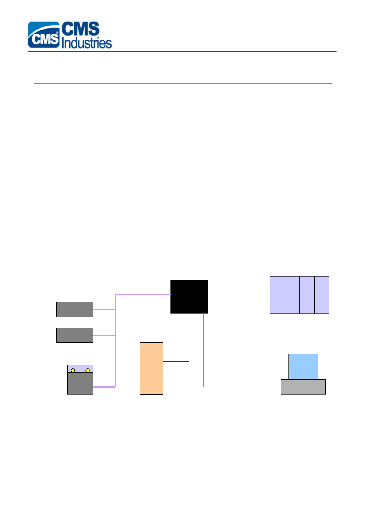
AXES DRIVES
canbus
INVERTER
serial
I
NTRODUCTION
P
URPOSE OF DOCUMENT
This document is meant for assistance support; therefore its aim is simplifying and speeding up
the diagnosis of any machining centre troubles.
For this purpose the following topics will be dealt with:
- Description of the main parts of OSAI automation project
- Description of the CNC and PLC basic structures and related interactions
- Description of PLC Debug operations
- Description of NC OSAI Backup and Restore operations
D
ESCRIPTION OF AUTOMATION PROJECT PARTS
The figure below displays the components of a typical NC OSAI Automation project
Peripherals
mechatrolink
ethernet
PC
OFFICE
CFP0110001/01 - 4 -
Page 5

Osai
- PLC
CNC
FUNCTIONS AND
PLC
FUNCTIONS
The main component of the automation project is the CNC
to as NC from now onwards))
a) Part-Program interpretation and execution
b) Interpolation and axis handling control
c) Management of Process Variables (E, @, L()…)
d) System parameterization
In particular, the NC OSAI integrates also the PLC (
machining centre. The PLC consists of a program written in a programming language called
WinPLUS which, once compiled and transferred into the NC memory, is run by the CPU of the NC
cyclically.
The PLC carries out the following tasks:
a) Manages the “Machine interface logic” , that is, manages all the Inputs/Outputs
(digital/analog, local/remote) of the machine.
b) Informs the machining centre operator about any anomalies, detected via screen
messages or warning lights; attends to stop the machining centre functions temporarily or
definitively based on the seriousness of such anomalies.
c) Enables the workpiece machining process to progress (Part-Program) and checks that at
the beginning and end of each programmed block all necessary conditions exist to be able
to carry on machining.
which carries out the following functions:
(Computer Numerical Control (referred
Programmable Logic Controller
) of the
d) Manages the requests made by the Part-Program via the M,S,T auxiliary functions.
e) Manages the requests made by the machining centre operator:
o selects the operation mode of NC (AUTOMATIC, MDI, JOG, HOMING …)
o starts, stops and resets the machining process
o manages the requests made via Softkey available on the PC OFFICE.
f) Manages the various automatic cycles so that they run concurrently with the machining
process.
g) Acquires process variable values and axis dimensions, checks axis-axis or axis-machine
frame collisions.
NC – PLC
DIRECT INTERACTON
The NC retentive memory houses a memory area called VARIABILI PLUS which you can access
both from PLC and NC (from Part-Program or by accessing the related variable list). This memory
are is provided with 256 full format variables (subdivided into boolean variables) and 64 floating
point variables.
INTERACTION
CFP0110001/01 - 5 -
Page 6

Osai
- PLC
On the PLC side these memories subdivide into GW memories (bit-to-bit definable, in case) and in
GD memories respectively. On the NC side such variables are seen as variables @ follone by a max
10-character name. Type, name and address are declared in the special section “LOGIC CONF” in
AMP.
For any necessary in-depth details refer to the OSAI “AMP” Manual (code Osai 45006666T).
INDIRECT INTERACTION
The NC has a system memory area called area S; it also reserves part of the M area to interface
with the PLC transparently for the end user.
For instance, to carry out the following operations you need to:
- request for the PLC consent to execute each M,S,T code….
- request for the PLC consent to start moving an axis
- request for the PLC consent to declare an axis movement completed
While waiting for the PLC response, the NC stops the Part-Program execution on the wait
command.
The PLC cyclically controls the area S or area M memories, that are connected with the various NC
controls. After checking the presence of all necessary conditions, it attends to the specific
management and signals the acceptance of the request (ACK) on other memories to enable
continuing the processes under way.
For any necessary in-depth details refer to the OSAI “ WinPLUS Application” Manual (code Osai
45006861T).
SW
STRUCTURE OF THE
This paragraph deals with the organization of the NC files and the description of the most
important ones, with regard to the purpose of this document.
The NC Hard Disk is partitioned into the following 4 logic partitions:
C and D : they are system disks containing the system files relating to the specific NC SW release.
E: this disk is reserved to the machining centre manufacturer, containing all NC parameterization
data.
F: this disk is reserved to the machining centre manufacturer and to the end used; it contains all
workpiece machining cycles (Part-Program) and any other machining centre operating cycles
(paramacro, tool change programs, etc.)
NC
The peculiar files and folder are mentioned below:
E:\AMP : folder where the various AMP (Adjustable Machine Parameters) reside, i.e., the
system characterization files.
CFP0110001/01 - 6 -
Page 7

Osai
- PLC
E:\OEM\EXE : folder where the machining centre manufacturer applications reside (CMSKMG,
CMSCON, CMSRST). These DOS Real Time applications are run by the NC in parallel
with all other activities.
E:\LOG\WIN: folder containing some PLC configuration files, the message files
and the Canbus line configuration files.
F:\CMSKMG : folder containing the CMSKMG application configuration files.
F:\UPP : folder containing the Part-Programs and any auxiliary programs by the machining
centre manufacturer (tool change cycles, workpiece loading/unloading cycles, …)
AMP
By the related utility function it is possible to define up to 4 AMP’s. In most cases one single AMP is
enough for NC characterization. At other times it is necessary to define more than one of them, as
the machining centre can adopt configurations needing different parameterizations (machining
centres equipped with Gantry tables, machining centres where no axes can be added or removed
according to the operations to carry out, …). In this case it will be the end user’s task to select the
necessary AMP each time and restart the NC for activation.
The following features can be defined for each AMP:
- number of processes and related characterizations
- number of axes for each process and related characterization
- process variables
- logic interfacing variables (PLUS Variables)
A
PPLICATIONS BY MACHINING CENTRE MANUFACTURER
Any Applications by the Machining Centre Manufacturer which can be installed on the machining
centre NC are described below
- CMSKMG : this application attends to the serial interface between PLC and spindle Inverter.
It is characterized by the CMSKMG.IMP and CMSKMG.CFG files. In particular the CMSKMG.IMP file
defines the number of the Inverter, the number of electrospindles, the number of tool magazines,
the number of tools and the related coupling of each head.
Also the Machining Centre Manufacturer Applications residing on the PC OFFICE (Els Manager, Tool
Manager,…) use this information.
- CMSRST : application for resetting the electrospindle life, when they are replaced.
- CMSCON : application used for triggering the other applications.
The latest versions of the CMSKMG application are provided with improved diagnostic functions.
In this connection the diagnostic file F:\CMSKMG\CMSKMG.LOG has been provided, where a
certain number of signals from the CMSKMG.EXE application is stored. This number depends on
the value of the #DEB parameter present in the file CMSKMG.CFG, which can adopt the following
values:
#DEB 0 : Minimum signal level (default)
CFP0110001/01 - 7 -
Page 8

Osai
- PLC
#DEB 1 : Medium signal level
#DEB 2F: Maximum signal level with output on file CMSKMG.LOG
#DEB 2S: Maximum level with screen output (subject to assignment of video resource to
the CMSKMG.EXE application)
N.B.: folder E:\OEM\AMP1 contains the OEM_CONF.TXT file. This file defines the priority levels
and the video resources associated with the various applications.
By default the video resource is assigned to CMSCON application.
Should any problems arise with the spindle, it is possible to assign the video resource to the
CMSKMG application, to display some additional information which might turn useful during the
diagnostic phase. After making the changes prompted below it is necessary to recompile the AMP
and restart the NC for their acquisition.
Video resource to CmsCon (default) Video resource to CmsKmg
TI 127 512 0 CMSKMG.EXE TI 127 512 1 CMSKMG.EXE
* *
TQ 10 2 TQ 10 2
SM 1 1 SM 1 1
TI 129 512 1 CMSCON.EXE TI 129 512 0 CMSCON.EXE
It is advisable to restore the default configuration any way (#DEB 0 and video resource to the
CMSCON.EXE application) as sending messages implies a waste of extra time at any rate.
WIN
FOLDER
Inside the WIN folder the following files can be found:
- CANBUS line configuration file: CANBUS.DBM and CANBUS.RMP
- PLC message file:
-WINPLUS.ASC (former PLC versions)
-ITA.ASC, ING.ASC, FRA.ASC …… (new PLC versions)
-Initializzation/configuration files for the PLC:
-INITVAR
-INITBANC
-INITZERO
-INIT...
-(WINPLUS.DES is created by the NUMERICAL CONTROL automatically)
CFP0110001/01 - 8 -
Page 9
Osai
- PLC
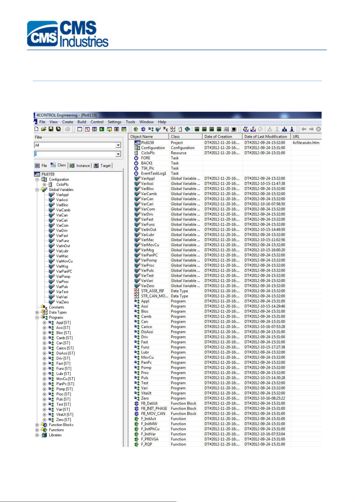
PLC S
The figure below shows an example of PLC application in WinPLUS environment.
TRUCTURE
CFP0110001/01 - 9 -
Page 10

Osai
- PLC
As illustrated by the figure below the PLC is structured into more modules: configuration modules
(CicloPLC.res), variable definition modules (Varxxxx.gvl), code definition modules (xxxx.st) and
other auxiliary modules (constant definition, structure definitions, functions, functional blocks and
various libraries).
In particular:
- CicloPLC.res : lists all the tasks of the PLC project
- VarInOut.gvl : lists the definitions of all I/O’s of the PLC project
- VarMsg.gvl : lists the definitions of all messages of the PLC project
- VarMac.gvl : lists the definitions of the main variables of the machining centre in hand
- VarCom.gvl : lists the definitions of the standard variables shared by all the PLC projects
- Fast.st, Assi.st, Proc.st, Driv.st, Zero.st, Funz.st: these are the main program blocks
V
ARIABLE NOMENCLATURE
The nomenclature of variables has been the target of a great effort of standardization, so as to
simplify the understanding of the various projects. The following tables describe the conventions
adopted.
TABLES OF SYMBOLS FOR I/O SIGNAL NOMENCLATURE
Convention adopted for machine I/O nomenclature.
INPUTS
Derivative, generic, … INP
Flow switch FL
Circuit breaker QF
Motor-protective circuit breaker QM
Braking resistance RR
Selector SA
SYMBOL
Button SB
Luminous button/selector SH
Level sensor SL
Pressure sensor SP
Position sensor SQ
Rotation sensor SR
CFP0110001/01 - 10 -
Page 11

Osai
- PLC
Temperature sensor ST
Thermostat TR
OUTPUTS
Derivative, generic, … OUT
Indicator light, lamp, HL
Instantaneous relay KA
Power contactors KM
Electromagnetic brake YB
Solenoid valve YV
TABLE OF SYMBOLS FOR GLOBAL VARIABLE NOMENCLATURE
Legend: xxxx Name of block where the memory is set
y System memory initials (S or M)
VARIABLE
RANGE
VOLATILE MEMORIES 1 BIT
VOLATILE MEMORIES 8 BIT BYTE
VOLATILE MEMORIES 16 BIT WORD (UNSIGNED)
VOLATILE MEMORIES 16 BIT INT (SIGNED)
VOLATILE MEMORIES 32 BIT DOUBLE WORD (UNS.)
VOLATILE MEMORIES 32 BIT DOUBLE INT (SIGNED)
0÷1
0÷255
0÷65535
-32768÷32767
0÷294967295
-2147483648÷2147483647
SYMBOL
MM_xxxx
MB_xxxx
MW_xxxx
MI_xxxx
MDW_xxxx
MDI_xxxx
VOLATILE MEMORIES 64 BIT LONG REAL floating point 64bit precis. MLR_xxxx
VOLATILE MEMORIES TIME MT_xxxxx
RETENTIVE MEMORIES 1 BIT
RETENTIVE MEMORIES 8 BIT BYTE
0÷1
0÷255
RM_xxxx
RB_xxxx
CFP0110001/01 - 11 -
Page 12

Osai
- PLC
RETENTIVE MEMORIES 16 BIT WORD (UNSIGNED)
RETENTIVE MEMORIES 16 BIT INT (SIGNED)
RETENTIVE MEMORIES 32 BIT DOUBLE WORD (UN.)
RETENTIVE MEMORIES 32 BIT DOUBLE INT (SIGN.)
RETENTIVE MEMORIES 64 BIT LONG REAL floating point 64bit precis. RLR_xxxx
VOLATILE MEMORIES 1 BIT NC
VOLATILE MEMORIES 8 BIT NC BYTE
VOLATILE MEMORIES 16 BIT NC WORD (UNSIGNED)
VOLATILE MEMORIES 16 BIT NC INT (SIGNED)
VOL. MEMORIES 32 BIT NC DOUBLE WORD (UNS.)
VOL. MEMORIES 32 BIT NC DOUBLE INT (SIGNED)
0÷65535
-32768÷32767
0÷294967295
-2147483648÷2147483647
0÷1
0÷255
0÷65535
-32768÷32767
0÷294967295
-2147483648÷2147483647
RW_xxxx
RI_xxxx
RDW_xxxx
RDI_xxxx
yM_CN
yB_CN
yW_CN
yI_CN
yD_CN
yDI_CN
VOL. MEMORIES 64 BIT NC LONG REAL floating point 64bit precis. yLR_CN
TABLE OF SYMBOLS FOR GLOBAL VARIABLE NOMENCLATURE (V
VARIABLE
RANGE
MEMORIES 1 BIT
MEMORIES 8 BIT BYTE
MEMORIES 16 BIT WORD (UNSIGNED)
MEMORIES 16 BIT INT (SIGNED)
MEMORIES 32 BIT DOUBLE WORD (UNS.)
MEMORIES 32 BIT DOUBLE INT (SIGNED)
MEMORIES 64 BIT LONG REAL floating point 64bit precis. LOC_MLR
0÷1
0÷255
0÷65535
-32768÷32767
0÷294967295
-2147483648÷2147483647
OLATILE ONLY
)
SYMBOL
LOC_MM
LOC_MB
LOC_MW
LOC_MI
LOC_MDW
LOC_MDI
MEMORIES TIME LOC_MT
CFP0110001/01 - 12 -
Page 13

Osai
- PLC
NOTES AND EXAMPLES
LOCAL VARIABLES
The LOCAL variables differ from the GLOBAL variables in that they can be used only in the module
they are defined for. To distinguish them from the GLOBAL variables the programming department
decided to prefix the variable format type with the string “LOC_” but without indicating the name
of the block xxxx (as they are defined and used always in the same block).
Examples: LOC_MW_RisultatoConversione , LOC_MM_ConversioneInCorso.
CONSTANT
With WinPlus it is advisable to use some symbolic values in the various computational expressions,
i.e. some CONSTANTS, instead of absolute values whose meaning is not easily grasped.
Generic constants defined in the VarCom.gvl module:
KI_PROCESSO1 : INT:= 1 ;
KT_10MS : TIME:= T#10ms ;
Specific constants defined in the VarAssi.gvl module:
KI_ASSI_NUM_BIT_FEED_OVR : INT:= 5 ;
KI_ASSI_NUM_BIT_SPEED_OVR : INT:= 4 ;
NAME OF VARIABLE
Each name of variable is made up by the variable type, the name of the block (with exceptions)
where the variable is set and by a very concise description. The meaning of the action must refer
to logic state 1 (TRUE).
Exceptions: the name of the block does not need to be indicated in case of LOCAL variables,
system variables, I/O signals and is omitted in case of variables indicating M/S/T functions.
With WinPlus the name of a variable can be maximum 32-character long.
Per costruirlo unire fra loro TUTTE le parole della relativa descrizione, scrivendo in maiuscolo
l’iniziale di ciascuna parola tranne il tipo di variabile che va scritto interamente in maiuscolo
utilizzando il carattere “_” come separatore.
Ulteriori convenzioni vengono utilizzate per alcuni tipi di variabili utilizzate ad esempio per la
decodifica di softkey , per i messaggi , per i parametri formali delle funzioni o per variabili
rappresentanti maschere di bit.
Negli esempi e nelle note che seguono sono indicati tutti i casi previsti.
Esempi :
Indirizzo (opzionale) Nome Variabile: Tipo
M 1004,04 INP_OkModuloEmergenza Segnale ingresso
CFP0110001/01 - 13 -
Page 14

Osai
- PLC
M 1010,00 SQ_PortaDxAperta Sensore di posizione
M 1130,03 YV_SoffiatoreUtensile Elettrovalvola
M 1355,00 MM_ASSI_AsseXInMovimento Bit Globale da modulo ASSI.ST
MM_VARI_AuxGestioneZone Bit Globale da modulo ASSI.ST
(senza associazione a variabile
pagina vecchia PLUS)
GW 94 RI_CAMB_UtensileMandrino INT Ritentivo da modulo CAMB
MW 2710 MI_ZERO_MskRichiestaZeroAssi INT Globale da modulo ZERO.ST
S 20,07 SM_CN_ResetProcesso1 Bit di sistema
M 143,05 MSG_CAMBIO_CambioUtInCorso Messaggio
M 3801,05 M21 Funzione M
LOC_MI_Contatore INT Locale
TABELLA DEI SIMBOLI PER NOMENCLATURA ULTERIORI STRUTTURE DATI
Per le convenzioni adottate per la nomenclatura di Funzioni , Temporizzatori , Pulse , ecc . riferirsi
alla seguente tabella:
STRUTTURA DATI
FUNZIONE F F_EseguoSomma
BLOCCO FUNZIONE FB FB_DatiUt.
Par. d’Ingresso Funzione FNI_MI FNI_MI_Addendo1
Par. d’uscita Funzione FNO_MI FNO_MI_Risultato
Timer tipo TON TimerTon TimerTon_RitardoInitMotori
Timer tipo TOFF TimerToff TimerToff_Spegnimento
Timer tipo TP TimerTp TimerTp_Soffiatore
Pulse salita Pulse_Up PulseUp_PrimoPowerOn
SIMBOLO
ESEMPIO
Pulse discesa Pulse_Down PulseDownResetCnProc1
Struttura Dati STR_ STR_MOVCU_ArrayCanPhaseCu
Per ulteriori approfondimenti consultare il Manuale OSAI “WinPLUS: Manuale di Programmazione”
(cod.Osai 45006877B).
CFP0110001/01 - 14 -
Page 15

Osai
- PLC
D
EBUG
Una volta scritto il codice è necessario compilare il progetto prima di trasferirlo nel CN (download).
Per compilare il progetto cliccare sull’icona indicata in figura. Con alcune versioni di WInPLUS
l’operazione di compilazione necessita della relativa chiavetta HW.
Nel caso di errori di compilazione provvedere alla relativa correzione.
Per esempio:
PLC
In questo caso cliccando due volte sulla prima riga errata nella lista errori è possibile rintracciare
velocemente il punto in cui l’errore è presente. Apportare le correzioni del caso e ripetere
l’operazione di compilazione. Il risultato che si deve ottenere è il seguente:
CFP0110001/01 - 15 -
Page 16

Osai
- PLC
A questo punto è possibile scaricare il progetto in macchina cliccando sull’icona indicata nella
seguente figura.
Alla seguente richiesta cliccare su “Si” come indicato in figura:
Ignorare le eventuali segnalazioni di Errore / Warning che vengono emesse al termine
dell’operazione di Download. Verificare che l’operazione si concluda con la scritta “… download
finished” come indicata nella figura seguente:
CFP0110001/01 - 16 -
Page 17

Osai
- PLC
R
ICERCHE VELOCI
I seguenti comandi sono particolarmente utili nelle fasi di debug PLC e diagnostica:
a) “Cerca in files” ⇒ ctrl+i
b) “Vai alla linea” ⇒ ctrl+g--
ULTERIORI OPERAZIONI DI DEBUG
Esistono inoltre i seguenti strumenti di debug che consentono di eseguire operazioni di diagnosi e
debugging più complesse e nel caso di utilizzo dei breakpoint anche pericolose. Il relativo utilizzo è
riservato a personale qualificato.
a) Watchpoint
b) Watch List
c) Breakpoint
CFP0110001/01 - 17 -
Page 18

Osai
- PLC
B
ACKUP & RESTORE
It is possible to save all the files which are on the NC at the same time, without the need to store
them separately.
Please note that the PLC project is on the PC OFFICE and should be saved separately as for all
other applications which are on PC OFFICE.
B
ACKUP
The following procedure describes the steps to be done to save all the data of the NC on the PC:
You must start from the condition
1. CN activated
2. Machine in Emergency stop
CN
CN
• Press UTILITY
• Press BOOT CONTROLLER
• Press MODE
CFP0110001/01 - 18 -
Page 19

Osai
- PLC
• Press SETUP
• Press BOOT
• Press REBOOT
CFP0110001/01 - 19 -
Page 20

Osai
- PLC
• Compare il messaggio “ARE YOU SURE YOU WANT TO BOOT THE CNC”
• Cliccare su YES
Wait for the complete reboot of the system
• Wait until you see the message “CNC IS IN SETUP MODE”
• Press SECURITY shown in figure:
• Press BACKUP and specify the path and name of the backup to be created:
• Create a new folder “BCKxxxx” (xxxx represents the serial number of the machine).
CFP0110001/01 - 20 -
Page 21

Osai
- PLC
• Open the folder you just created, specify the file name and press SAVE
• Select “All the control” tag and press START:
• Wait for the end of the Backup operation, until it is shown the message “Operation
completed successfully!”
• Close the SETUP interface:
Press FILE
Press EXIT
• Into BOOT CONTROLLER interface, select MODE then press NORMAL to restart the CN in
standard mode and resume normal operation of the machine:
CFP0110001/01 - 21 -
Page 22

Osai
- PLC
• Press BOOT, then REBOOT
• Press YES and wait the end of the operation.
• Restart the machine.
CFP0110001/01 - 22 -
Page 23

Osai
- PLC
R
ESTORE
The following procedure describes the operations to load all the data from the PC to the NC:
Requerements:
1. CN activated
2. Machine in Emergency stop
• Press UTILITY
• Press BOOT CONTROLLER
CN
• Press MODE
CFP0110001/01 - 23 -
Page 24

Osai
- PLC
• Press SETUP
• Press BOOT
• Press REBOOT
• It is shown the message “ARE YOU SURE YOU WANT TO BOOT THE CNC”
• Press YES
CN runs the Reboot.
• Wait until it is shown the message “CNC IN SETUP MODE”
CFP0110001/01 - 24 -
Page 25

Osai
- PLC
• Select the SECURITY shown in figure:
• Press RESTORE, select BROWSE… e indicare il percorso ed il nome del file di backup da
ripristinare.
• Select the three options “System area”, “OEM area”, “User area”:
• Press START and wait for the completion of recovery operations CN, which is specified by
the message “Operation completed successfully!”
CFP0110001/01 - 25 -
Page 26

Osai
- PLC
• Close SETUP interface:
Press FILE
Press EXIT
• In the BOOT CONTROLLER interface, select MODE, then press NORMAL to restart the CN
in standard mode and resume normal operation of the machine:
CFP0110001/01 - 26 -
Page 27

Osai
- PLC
• Press BOOT then REBOOT
• Select YES and wait the end of the process.
• Shut down and restart the machine.
R
IFERIMENTI
Documento: install Win e CN v22.doc
Documento: WnBBck.doc
Documento: WnBRst.doc
CFP0110001/01 - 27 -
 Loading...