

Page 1

Camera Link Line Scan Camera
CM200P-C
CM100P-C
CM050P-C
User’s Manual
A153MN00213
January.30.2007
CMICRO Corporation
Page 2

Table of Contents
Introduction .....................................................................................................................1
Safety Precautions..........................................................................................................2
1. Getting Started............................................................................................................6
2. Product Overview........................................................................................................7
2.1 Summary .......................................................................................................................7
2.2 Key Features .................................................................................................................7
2.3 Functions.......................................................................................................................7
2.4 Camera Specifications .................................................................................................8
2.5 Spectral Sensitivity.......................................................................................................9
3. Description of Functions............................................................................................10
3.1 Name and Function ....................................................................................................10
3.2 Connector Pinout........................................................................................................11
3.2.1 Camera Link Connector.............................................................................11
3.2.2 Power Input Connector..............................................................................11
3.3 Input control signal ....................................................................................................12
3.4 Power Supplies...........................................................................................................13
3.5 Serial Interface............................................................................................................13
3.6 Data output signal ......................................................................................................13
3.7 Operation Timing and Exposure image....................................................................14
3.7.1 Operation Timing........................................................................................14
3.7.2 Exposure image when using external EXYNC signal..............................15
4. Operation ..................................................................................................................16
4.1 Cable connection........................................................................................................16
4.2 Camera Link serial communication ..........................................................................17
4.2.1 Specifications of Camera Link serial communication.............................17
4.2.2 Protocol.......................................................................................................17
4.2.3 Communication flow chart ........................................................................18
4.2.4 Command table ..........................................................................................19
4.2.5 Command error code.................................................................................19
4.2.6 Command reference...................................................................................20
5. Mechanical Characteristics .......................................................................................23
5.1 Camera Dimensions ...................................................................................................23
Page 3

Introduction
Thank you for having purchased our “CM200P-C”.
Please read this manual carefully before using this camera.
This manual should be easy to refer to whenever information is needed.
In case this manual is lost or damaged, please call your delivery agent or the sales division of
our company for replacement.
The specifications noted are for our CM200P-L model camera. The CM100P-L and CM050P-L
share most of the same specifications. Differences are noted.
■Disclaimer:
1. All rights reserved. Reproducing this manual in part or in whole without authority
permission from this company is prohibited.
2. The information in this manual may be subject to change without prior notice.
3. We have made sure that all information contained in this manual is accurate. However, in
the case that any mistakes are found or the contents are not clear, please call your
delivery agent or sales division of our company.
4. We assume no responsibility whatsoever for any damages resulting from improper use of
camera, regardless of Article 3.
■ Trademark:
All brand names and product names in this manual are trademarks or registered tradem arks
of their respective companies.
1
Page 4
Safety Precautions
To operate this camera safely and properly, this section should be read and understood
completely. Failure to do so may result in damage to the equipment, personal injury or
damage to property.
Please keep this manual for future reference.
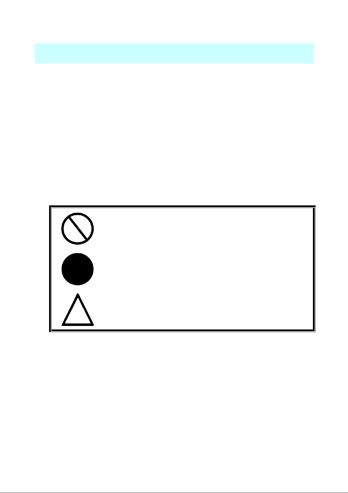
■About the symbols:
Various warning and caution symbols are used in this manual for operating this camera
safety and properly. Please refer to the following to understand the meaning before continuing
with this manual.
■Meaning of the symbols:
PROHIBITION
STRICT OBSERVANCE
PRECAUTION
2
Page 5
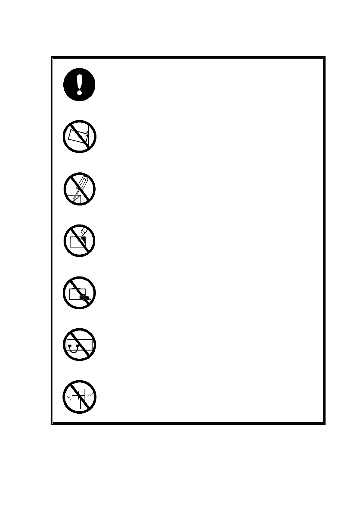
■Warning and Caution:
Observe all warnings and cautions in the instructions of the PC or other
peripheral equipment used along with this camera.
Failure to do so may cause fire, electric shock or personal injury.
DO NOT subject camera to strong vibrations or shocks.
DO NOT disassemble or modify camera.
Disassembling or modifying the camera is extremely dangerous. It can also
adversely affect the performance and function. We have the right to refuse
repairing any camera with unauthorized modified cameras.
DO NOT expose to water or chemicals.
DO NOT attach extraneous material.
DO NOT wire incorrectly.
Please make sure you understand this manual fully before wiring.
DO NOT put camera close to TV or radio.
To expose camera to magnetic or electrical field could cause problems or
failure.
3
Page 6
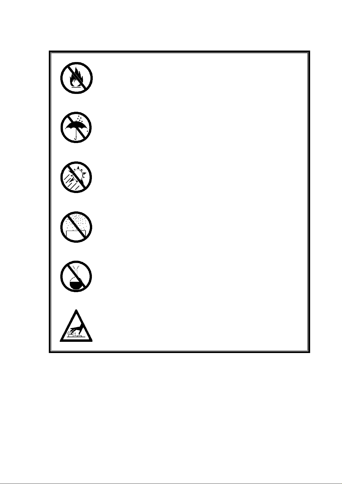
DO NOT use camera close to fire.
DO NOT expose camera to high humidity or rain.
DO NOT expose camera to direct sunlight.
DO NOT expose camera to dust or dirt.
DO NOT expose camera to chemical gases.
CAUTION! -- STATIC ELECTRICITY
Do not directly touch the metallic portion of the camera, such as the
terminal, connector, or IC. Static electricity may occur, damaging the
camera.
4
Page 7
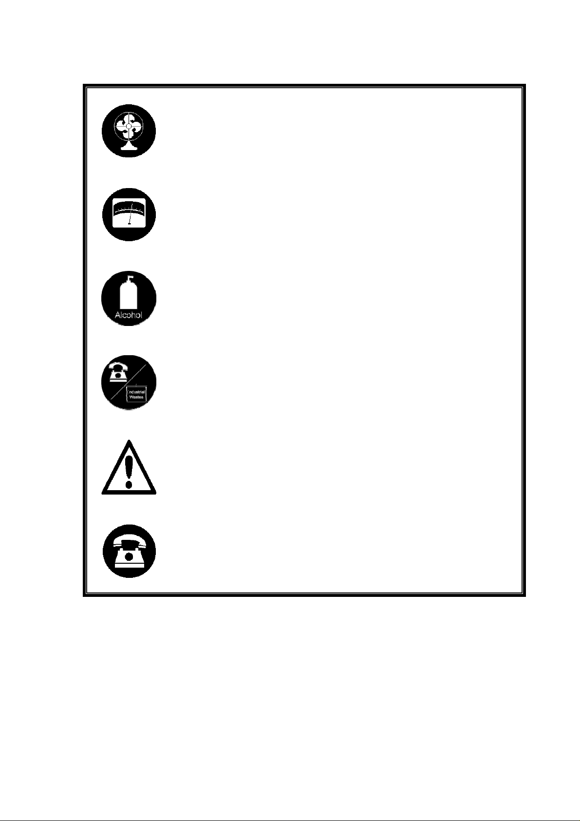
Ventilation:
Use camera in a well-ventilated place in order to diffuse heat. .
Range and Condition:
Use camera in rated range and under the conditions set forth by this manual
to avoid troubles.
Cleaning:
Clean camera when necessary to remove dirt. Use alcohol with soft and dry
cloth to remove heavy dirt. Then wipe off with dry cloth.
Do not clean camera with cleaner or fluxing materials such as thinner or
benzene.
Waste disposal:
When time to dispose of the camera, please make sure it is done so
according to local industrial waste regulations.
Malfunction?
Stop the camera immediately if you suspect a failure. If you continue using
the camera, it may have harmful effects on other equipment or could cause
fire, or short circuit.
Repair service:
Please contact your delivery agent or the sales division of our company.
5
Page 8
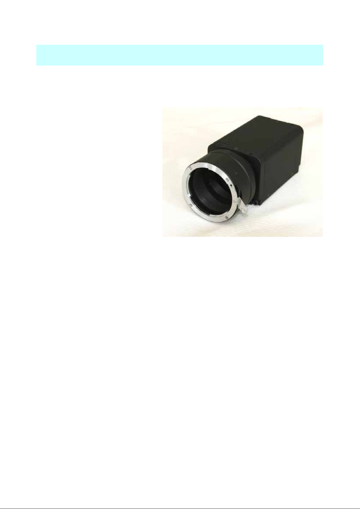
1. Getting Started
≪Unpacking the Camera≫
The package should include the followings:
□ CM200P-C Camera ×1
□ User’s Manual ×1
If any items are missing or damaged,
contact CMICRO immediately.
≪ Customer to furnish≫
The following items are not supplied
with the camera.
□ Camera lens ×1
□ Power cable ×1
□ Camera Link cable ×1
6
Page 9

2. Product Overview
2.1 Summary
The CMICRO CM200P-C monochrome camera is a high-sensitive and low noise compact line
scan camera with 2048 resolution
40MHz.
CM200P-C‘s functions such as exposure control, antiblooming and Camera Link output (Base
configuration) can provide superior cost performance in industrial, medical and agricultural
applications.
Note1: 1024 pixels on CM100P-C, 512 pixels on CM050P-C
2.2 Key Features
○ 2048 resolution
○ Pixel Size 14μm x 14μm, Low Noise, High-Sensitive
(2)
, Max 40MHz output data rate
(1)
, pixel size 14μm x 14μm operating at a data rate of
○ Camera Link 8 bit or 10-bit output
○ Exposure Control, Built-in antiblooming
○ Nikon F Mount, C mount Option
○ Very Compact Design: 56mm x 50mm x 126.75mm
○ Single Power Supply
○ Vibration Resistance, Corrosion Resistance at Connector, High-Reliability Camera taking
into account environment resistance.
Note2: 1024 pixels on CM100P-C, 512 pixels on CM050P-C
2.3 Functions
○ Selectable Sampling rate (20MHz or 4 0MHz)
○ Selectable Trigger Model (Internal or E xternal)
○ Selectable Exposure Con t rol Formula needed (Invalid or Level or PRIN input)
○ You can set Gain by 0.035dB
○ Selectable Horizontal Binning (ON or OFF)
7
Page 10
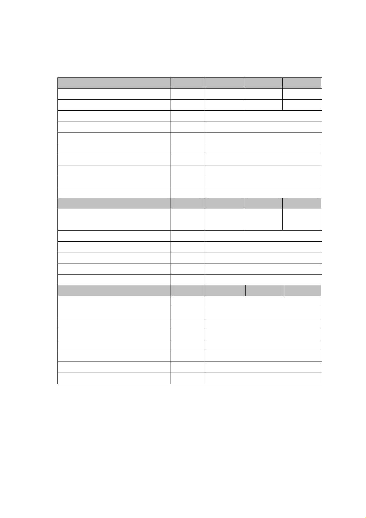
2.4 Camera Specifications
CM Series Performance Specifications
Physical Characteristics Units CM200P-C CM100P-C CM050P-C
Resolution Pixels 2048 1024 512
Aperture mm 28.67 14.34 7.17
Pixel size μm 14 x 14
Sensor Alignment (Basic point is1st CCD ) mm ΔX=±0.2、ΔY=±0.2、Δθ=±0.5°
Lens mount Nikon F Mount (C mount Option)
Power Input Connector 6pin, HR10-7P-6S (HIROSE)
Size(excluding lens and back-plate parts) mm 56x50x126,75(WxHxD)
Weight(excluding lens) g 315
Data Output Format Base configuration, 8-bit or 10bit
Data output Connector 26pin, 10226-2200VE(3M)
Operation ranges Units CM200P-C CM100P-C CM050P-C
Line Rate KHz
Data Format
Gain range dB Min -4 Max 20
Data Rate MHz Min 20 Max 40
Operating Temperature ℃ Min 0 Max 45
Power Supply DC V
Electrical Specifications Units CM200P-C CM100P-C CM050P-C
Responsivity
PRNU (Photo Response Non Uniformity) DN Typ6 M ax12 (8bit conversion)
Random Noise Pk-Pk @ 0dB Gain DN Typ1 (8bit conversion)
Signal noise @ 0dB Gain Ratio Typ850:1
Anti-blooming Output Saturation Voltage V Typ1.1
Power Dissipation Vin @ 15V mA
Power Consumption W Typ Approx.5.4
bit 8 or 10
DN/nJ/cm2Min6.3(-4dB) Typ40(12dB) Max100(20dB)
V/lx・sec Min18.9(-4dB) Typ120(12dB) Max300(20dB)
This information is subject to change without notice.
Min 0.30
Max 18.7
Min 11 Max 16 (Typ.12 ~15)
Min 0.30
Max 36.0
Typ360
Min 0.30
Max 66.6
8
Page 11
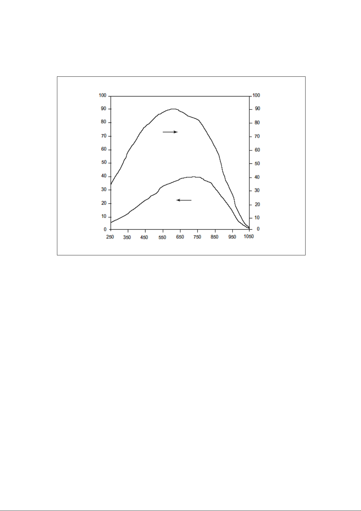
2.5 Spectral Sensitivity
)
2
Responsivity (V/μJ/cm
QE (Right Scale)
QE (%)
Responsivity (Left Scale)
Wavelength (nm)
9
Page 12
3. Description of Functions
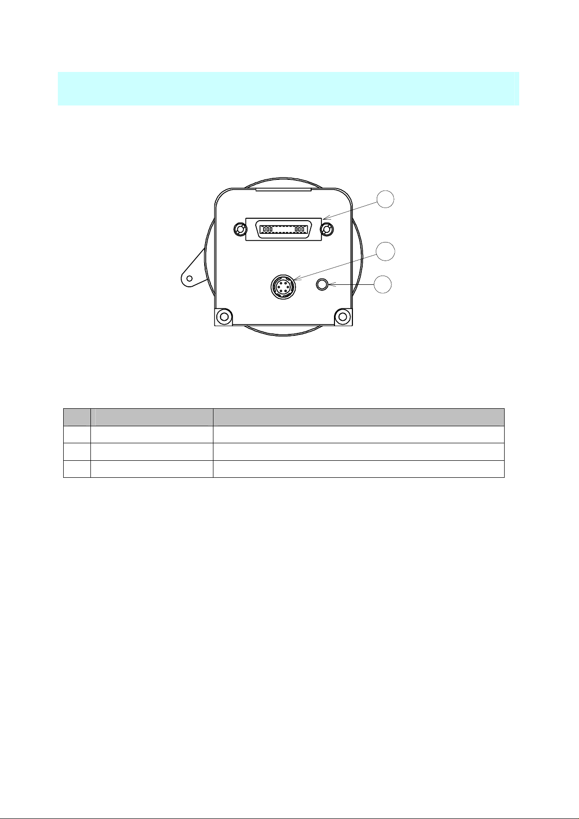
3.1 Name and Function
2
3
1
Back View
Name Function
Power Lamp Lights up green LED when camera power on.
①
Camera Link Connector Output digital image signal.
②
Power input connector Supply power to camera.
③
10
Page 13
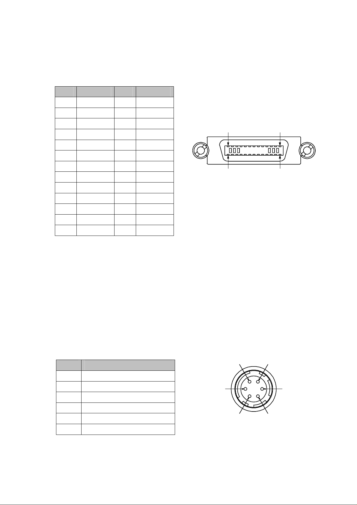
3.2 Connector Pinout
3.2.1 Camera Link Connector
Pin Sign Pin Sign
1 GND 14 GND
2 X0- 15 X0+
3 X1- 16 X1+
4 X2- 17 X2+
5 XCLK- 18 XCLK+
6 X3- 19 X3+
7 SERTC+ 20 SERTC8 SERTFG- 21 SERTFG+
9 CC1- 22 CC1+
10 CC2+ 23 CC211 CC3- 24 CC3+
12 CC4+ 25 CC413 GND 26 GND
13 1
26 14
Mating Part:10226-2200VE(3M)
Cable:14B26-SZLB series (3M)
CC1: EXSYNC signal To start line read out of external synchronization mode.
CC2: PRIN signal
CC3: Reserved
CC4: Reserved
3.2.2 Power Input Connector
Pin Signal
1 +12V to +15V
2 +12V to +15V
3 unconnected
4 unconnected
5 GND
6 GND
1
2
3
6
5
4
Mating Part:HR10-7P-6S(HIROSE)
11
Page 14
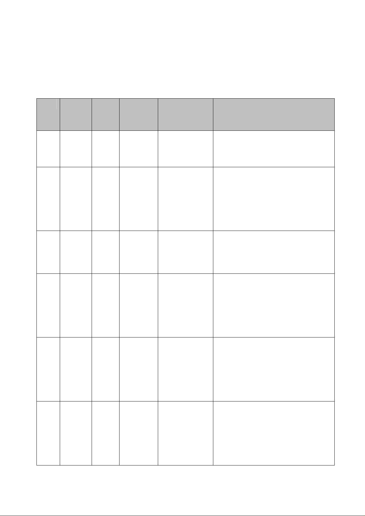
3.3 Input control signal
CM200P-L can control the line rate using EXSYNC. Line rate control is also available with
“Free Run Mode” instead of EXSYNC. You can control Exposure period PRIN signal.
EXSYNC, PRIN signal
Mode EXSYNC PRIN
0 Internal Internal No No Line Read out :
1 Internal Internal Yes Yes Line Read out : Free run (set_sync_time).
2
Input
from
Internal No No Line Read out: Falling edge of EXSYNC.
Assign
CYCLE
by Command
Assign
EXPOSURE PERIOD
by Command
Explanation
Free run (Max. line rate operation).
Exposure period: Max.
Exposure period: Command assignment of
set_exposure_time (Initial value is set before
command assignment).
When exposure period is assigned exceeding
line rate, exposure period becomes Max.
Exposure period: Max.(from one falling edge to
External
source
3
4
5 Input
Input
from
External
source
Input
from
External
source
from
External
next falling edge of EXSYNC).
Internal No No Line Read out: Falling edge of EXSYNC.
Exposure period: During HIGH polarity of
EXSYNC (from one rising edge to next falling
edge of EXSYNC).
During EXSYNC is LOW polarity, no charge
storage is executed.
Input
from
External
source
Internal No Yes Line Read out: Falling edge of EXSYNC.
No No Line Read out: Falling edge of EXSYNC.
Exposure period: During LOW polarity of PRIN
(from one falling edge to next rising edge of
PRIN).
During PRIN is HIGH polarity, no charge
storage is executed..
Exposure period: Command assignment of
set_exposure_time ( Initial value is set before
source
12
command assignment).
When exposure period is assigned exceeding
line rate, exposure period becomes Max.
Page 15
3.4 Power Supplies
The CM200P-C operates with single power supply of 12~15V (standard). You can also use
standard switching power supply as well.
For power requirements, please refer to performance specifications on page 8.
3.5 Serial Interface
The following functions can be controlled via serial interface. Executing write-setting
command allows free from new setting at next start.
Controllable functions are as follows.
○ Basic camera functions such as Gain, Offset, Source selection of synchronization
signal.
○ Selection and output of test pattern for debug
○ Cycle of internal synchronization signal
As serial interface is so simple protocol of ASCII communication, any special software is
not required.
CM200P-C can output setting status of command and parameter via serial interface.
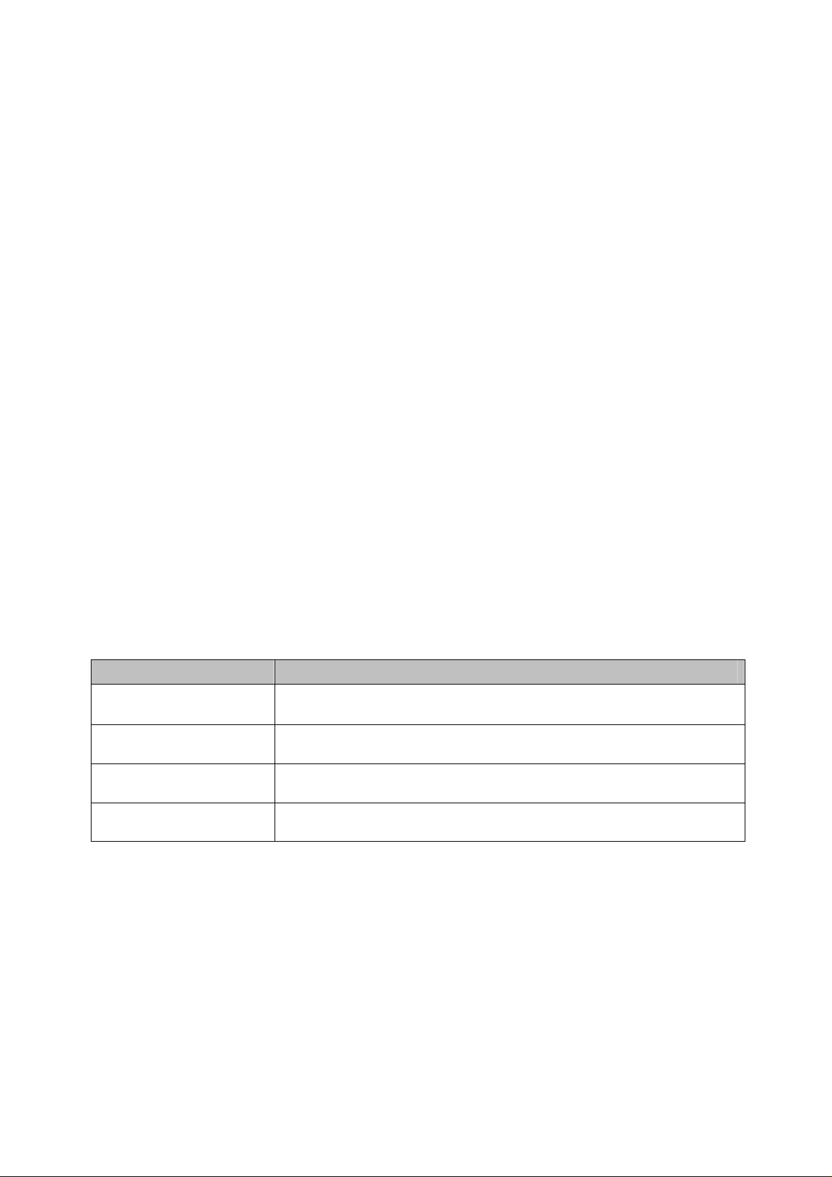
3.6 Data output signal
Timing signal Explanation
LVAL (HIGH polarity) Video data is valid at LVAL in HIGH polarity.
DVAL (HIGH Polarity) Video data is valid at LVAL in HIGH polarity.
STROBE (Rising edge) Sampling video data at rising edge
Video data Output signal of 8 or 10 bit in Camera Link (Base configuration) format.
13
Page 16
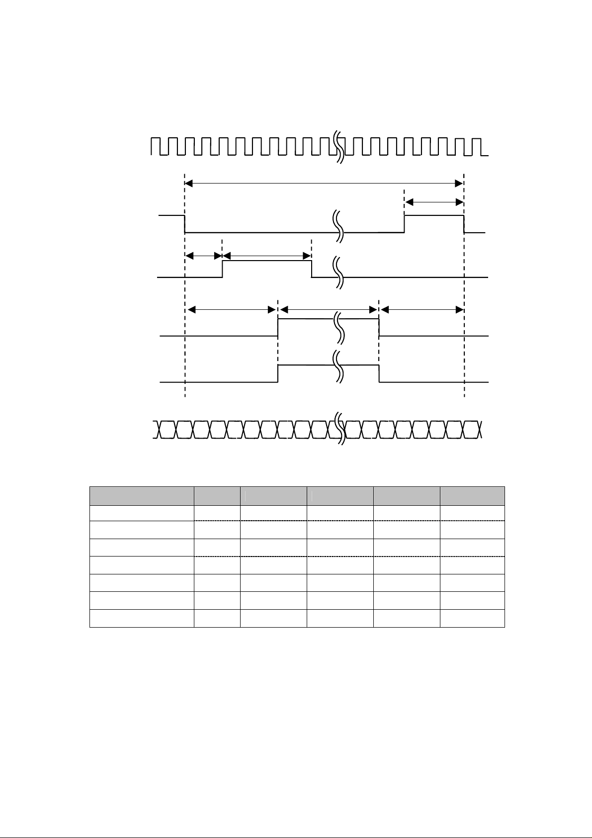
3.7 Operation Timing and Exposure image
3.7.1 Operation Timing
STROBE
EXSYNC
PRIN
LVAL
DVAL
DATA
tLINE PERIOD
twSYNC
thPR
thPR_HIGH
tTRANSFER tREADOUT tOVERHEAD
Symbol Unit Min. Typ. Max. Remarks
twSYNC
tLINE PERIOD
tTRANSFER
tREADOUT μs
tOVERHEAD μs
thPR μs
thPR_HIGH μs
Note1: 27.8μs on CM100P-C, 15.0μs on CM050P-C
Note2: Max. 25.6μs on CM100P-C, 12.8μs on CM050P-C
μs
μs
μs
1
(1)
53.5
2.2
51.2
0.1
0
0.75
3333
(2)
14
Page 17
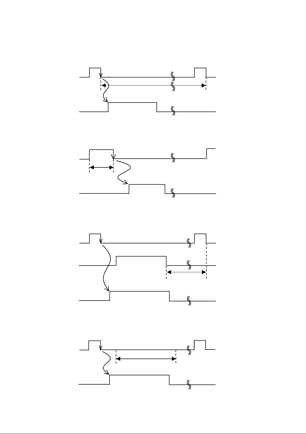
3.7.2 Exposure image when using external EXYNC signal
Mode 2
EXSYNC
Exposure period
LVAL
Mode 3
EXSYNC
LVAL
Mode 4
EXSYNC
Reading out
Exposure period
Reading out
PRIN
LVAL
Mode 5
EXSYNC
LVAL
Exposure period
Reading out
Exposure period(set_exposure_time)
Reading out
15
Page 18
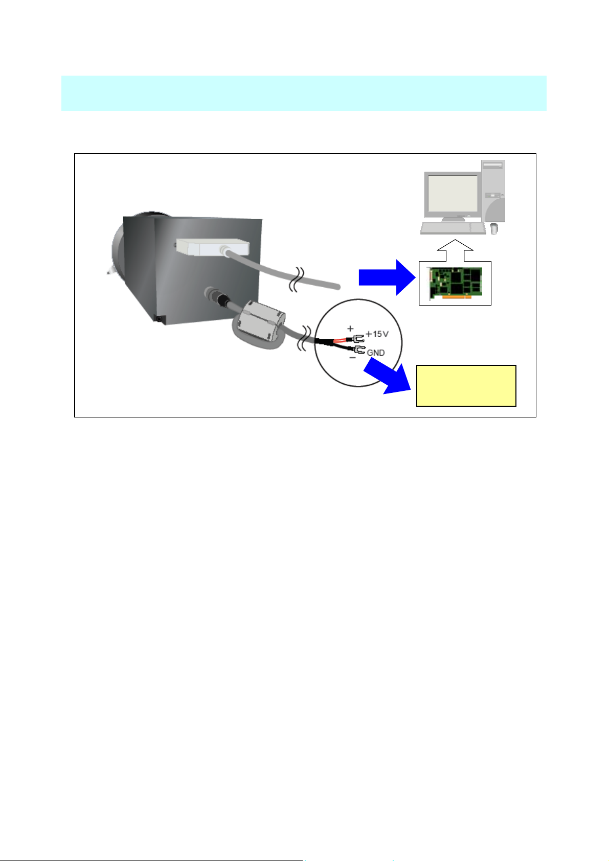
4. Operation
4.1 Cable connection
Power cable
≪How to connect cables≫
Power cable:
Connect Power cable with Power supply unit tightly.
Camera Link cable:
Connect Camera Link cable with Frame grabber board tightly.
Camera Link cable
Frame grabber
Power Supply
Unit
Note: To avoid potential shock hazard, be sure to turn off the power supply before connecting
/ disconnecting cables.
16
Page 19

4.2 Camera Link serial communication
4.2.1 Specifications of Camera Link serial communication
○ Communication speed (baud rate) : 9600 bps
○ Data length : 8 bit
○ Parity bit : Non
○ Stop bit : 1bit
○ Flow control : Non
With protocol, camera control will be executed by sending one communication command from
PC. One communication will be completed after sending the analyzed result back to PC.
You are requested to make communication command by command in order.
4.2.2 Protocol
○ ASCII base
○ Non echo
○ Command format
cmd parameter Return (CR : carriage return)
Punctuate command and parameter by one space.
17
Page 20
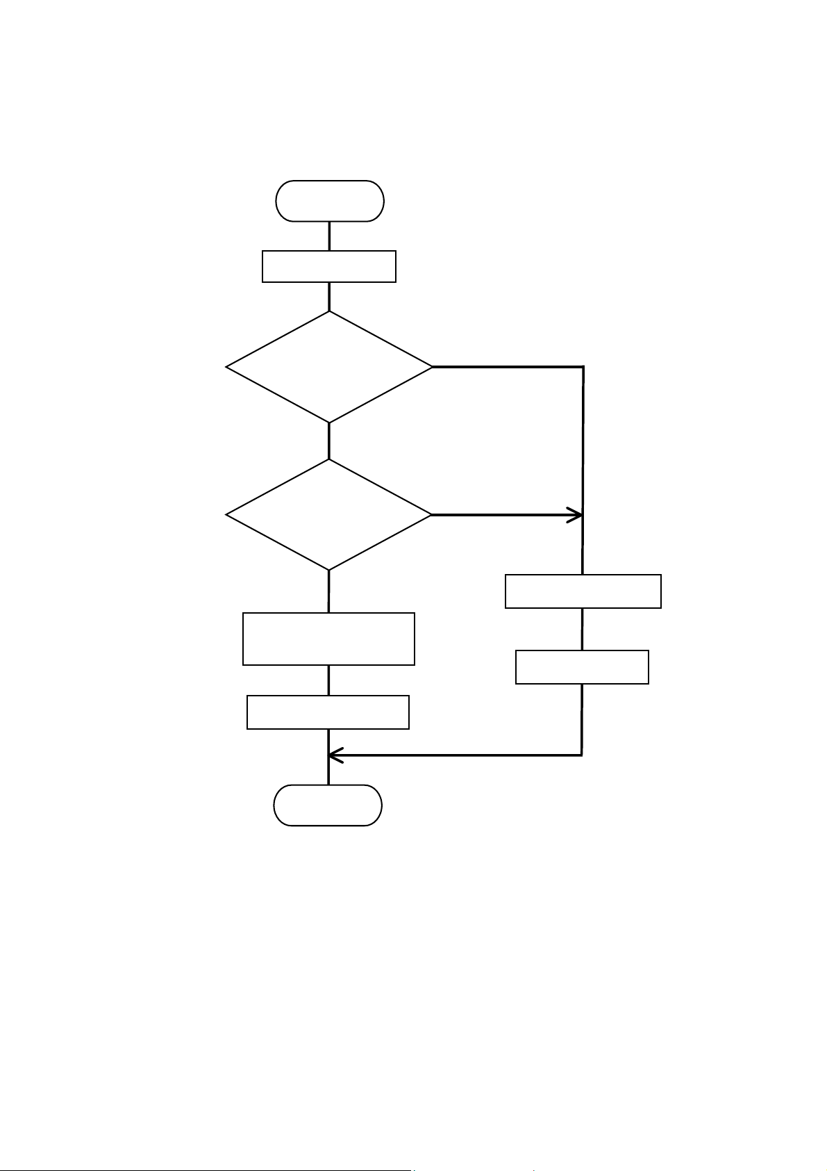
4.2.3 Communication flow chart
START
Command reception
COMMAND
CHECK OK?
NO
YES
PARAMETER
CHECK OK?
NO
YES
SEND ERROR CODE
SETTING CHANGE OF
CAMERA INSIDE
SEND >
SEND OK>
END
18
Page 21
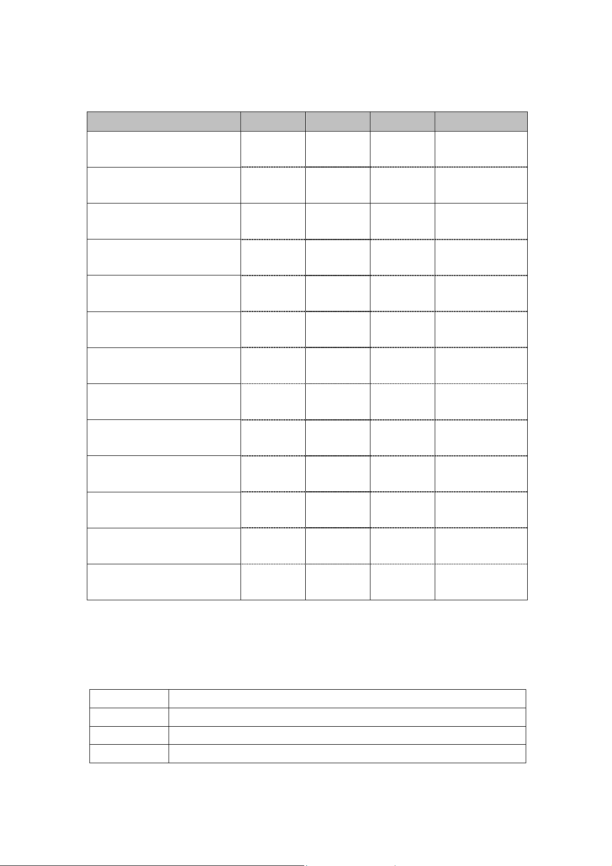
4.2.4 Command table
Command list
Command name Command Parameter Remarks Initial value
binning_switch
Set binning
set_gain
Set gain
set_pixel_offset
Set pixel offset value
set_sync_time
Set internal synchronization cycle
set_sync_mode
Set synchronization mode
set_exposure_time
Set exposure period
set data mode
Set output mode
set system clock
Set system clock
test_pattern_switch
bs Switch 0:off
1:on
sg Value 91 to 745 540
spo Value 0 to 60 32
sst micro_sec 53 to 3333
ssm Mode 0 to 6 0
set micro_sec 0 to 3333
sdm Mode 0:8bit
1:10bit
ssc Mode 0:40MHz
1:20MHz
tps Switch 0:off
0
53
54
1
0
0
(1)
(2)
Control test pattern
test_set_pattern
Set test pattern
get_camera_parameters
Read out camera set value
write_setting
Save set data
reset
Initialize camera
Note1: 27 on CM100P-C, 15 on CM050P-C
Note2: 28 on CM100P-C, 15 on CM050P-C
tsp Test number 0 to 3 0
gcp
ws
rst
4.2.5 Command error code
Error code Explanation
1 Nonexistent command
2 Parameter abnormal
1:on
3 Serial communication abnormal
19
Page 22
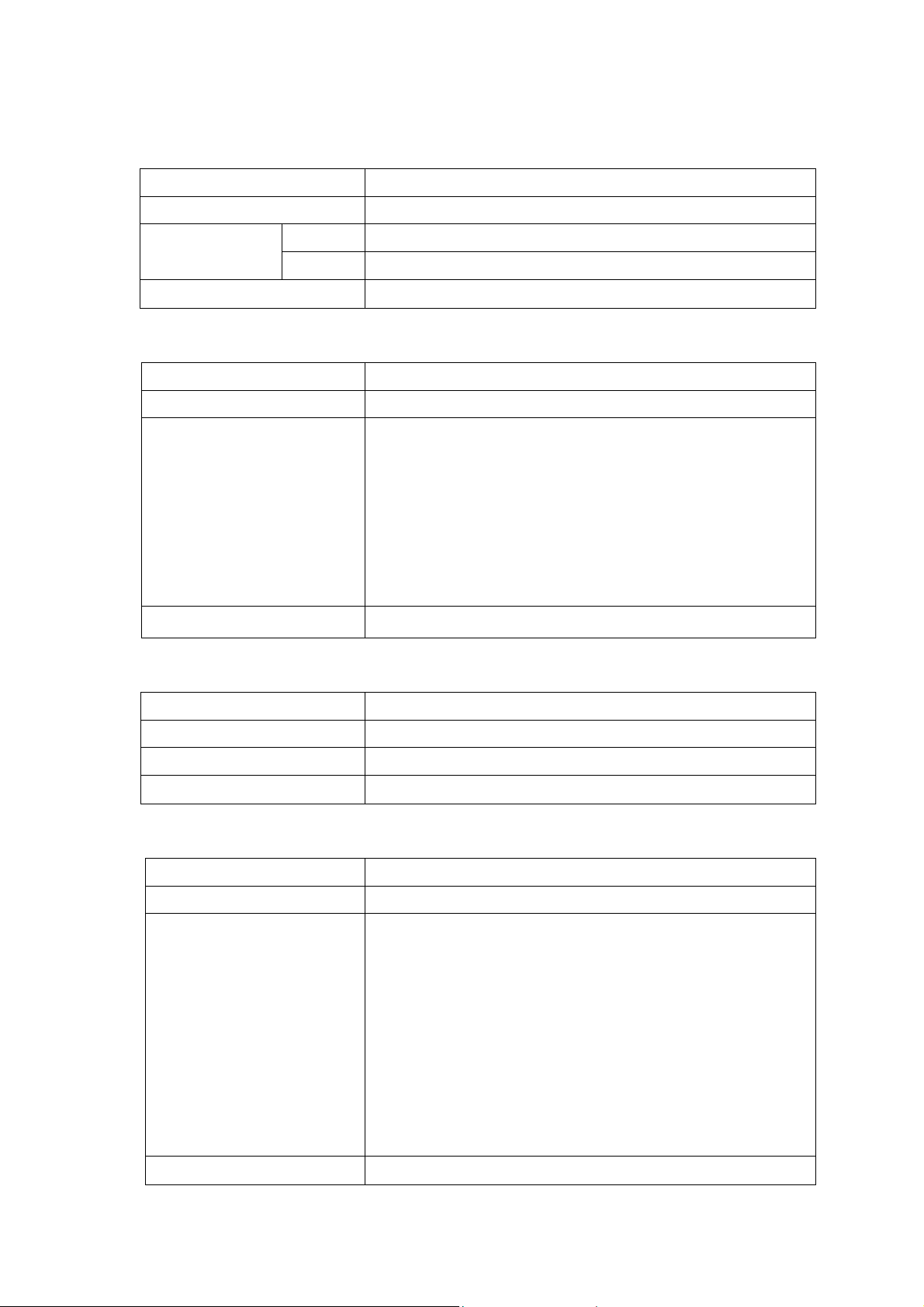
4.2.6 Command reference
1) binning_switch
Style bs “Value”
Explanation Switch binning status
0 Cancel binning Argument(value)
1 Validate binning
Example of command input bs 0 Return
2) set_gain
Style sg “Value”
Explanation Set gain
Argument(value) Input numerical value (91~745).
*Changing by 0.035dB approx. per 1 gain value.
*Value 0~9 or 746~1023 can be set but normal operation
is not guaranteed.
[Tentative gain value]
Example of command input sg 403 Return
3) set_pixel_offset
Style spo “value”
Explanation Set video output offset value (Initial value:32)
Argument(value) Input numerical value (0~60)
Example of command input spo 32 Return
4) set_sync_time
Style sst “micro_sec”
Explanation
Argument(micro_sec) *Input numerical value from 53~3333 for CM200P-C.
-4dB(0.6 times) :91 / odB(1 time):231 / 6dB(2 times): 403
12dB(4times):540/14dB(5times):575/ 20dB(10times):745
Set cycle(μs) of internal synchronization signal
When input argument of 53, set_sync_time becomes
53.3μs. *Input numerical value from 27~3333
for CM200P-C.
IWhen input argument of 27, set_sync_time becomes
27.8μs.
*Input numerical value from 15~3333 for CM200P-C.
ment of set system clock command is 1, set_sync_time
becomes 2 times.
Example ofcommand input sst 100 Return
20
Page 23
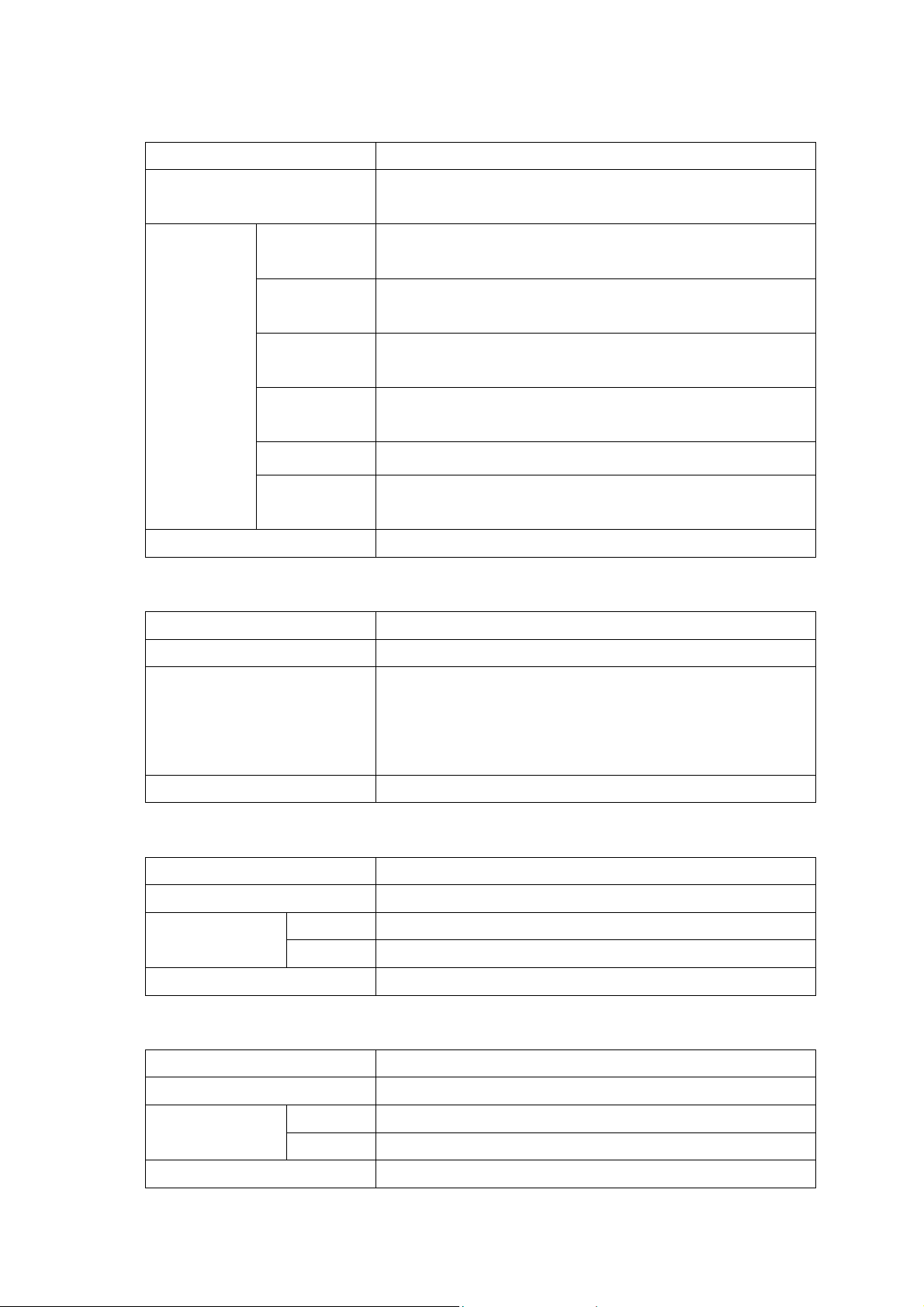
5) set_sync_mode
Style ssm “Value”
Explanation Set synchronization mode and exposure control.
Responding to input control mode 0~5.
Argument
(value)
Example of command input ssm 1 Return
6) set_exposure_time
Style Set “micro_sec”
Explanation
Argument(micro_sec)
0 Internal synchronization(Cycle : Max. speed),
No exposure control (Period : Max. exposure)
1 Internal synchronization(Cycle : Command assignment),
Exposure control (Period : Command assignment)
2 External synchronization,
No exposure control (Period : Max. exposure)
3 External synchronization,
Exposure control (EXSYNC level input)
4 External synchronization, Exposure control (PRIN input)
5 External synchronization,
Exposure control (Perid : Command assignment)
Set exposure period (μs)
Input numerical value from 0~3333.
Example of command input set 1000 Return
7) set data mode
Style sdm “Value”
Explanation Switch output mode
Example of command input sdm 0 Return
8) set system clock
Style ssc “Value”
Explanation Switch system clock
* When argument of set system clock command is 1,
set_exposure_time becomes 2 times.
0 Output bit is 8 Argument(value)
1 Output bit is 10
0 System cock is 40MHz Argument(value)
1 System cock is 20MHz
Example of command input ssc 0 Return
21
Page 24
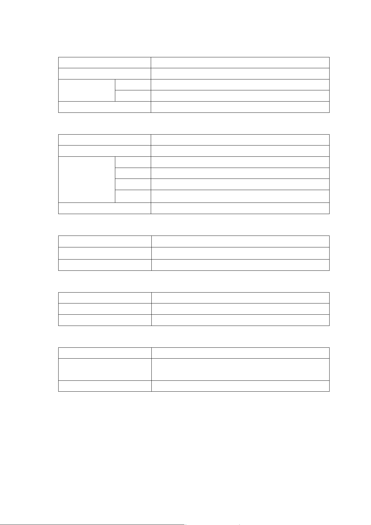
9) test_pattern_switch
Style tps “Value”
Explanation Switch On/Off of test pattern output
Example of command input tps 1 Return
10) test_set_pattern
Style tsp “Value”
Explanation Switch classification of test pattern output
0 Test pattern output is invalid (Output signal from sensor)Argument(value)
1 Test pattern output is valid
Argument(value)
Example of command input tsp 2 Return
11) get_camera_parameters
Style gcp
Explanation Read out present data set on camera]
Argument(value) Non
12) write_setting
Style ws
Explanation Write present set data into memory
Argument(value) Non
13) reset
0 Saw edge ripple
1 Triangle ripple
2 Lamp ripple
3 Crosshatch
Style rst
Explanation Set camera on default setting.
(For saving the setting, execute write_setting command)
Argument(value) Non
22
Page 25
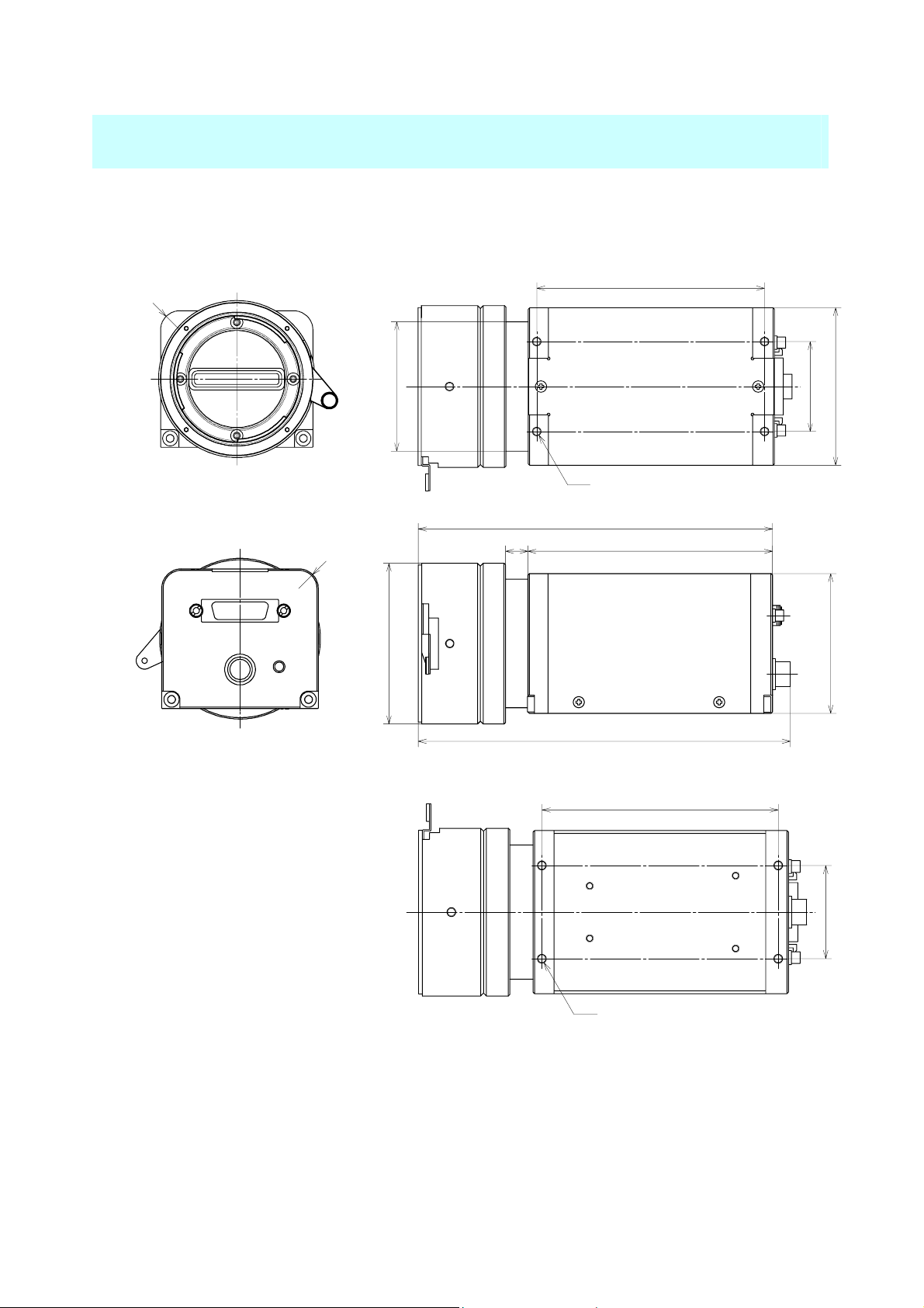
5. Mechanical Characteristics
5.1 Camera Dimensions
【Front View】 【Top View】
R
7
Φ46
81
32
56
4-M3
【Back View】 【Side View】
7
R
126.75
87.58
Φ57.5
133.05
【Bottom View】
81
50
32
Camera figure is subject to change without notice.
4-M3
≪Mounting Holes≫:
Four M3-holes with 5mm deep and 81x32mm pitch can be used for camera mounting.
Use M3 (3mm) Phillips head screw with 5mm length max. (Refer to Top/Bottom view)
23
Page 26

269-1, Hayashi-cho, Takamatsu,
Kagawa , 761-0301, Japan
Phone: +81-87-869-8310
Fax: +81-87-869-8320
E-mail: [email protected]
Web: http://www.cmicro.co.jp/index-e.htm
CMICRO Corporation
 Loading...