

Page 1

OWNER’S MANUAL
MODEL PT-35
POWER TILT & TRIM
COOK
MANUFACTURING CORPORATION
© COPYRIGHT - 2006 Part #52160 REVISION 5
Page 2

FOREWORD
Thank you for choosing a CMC product. This manual is designed to aid in installation and
maintenance of your PT-35 Power Tilt and Trim. Each part of the CMC PT-35 is machined
from the highest quality material to ensure many years of trouble free service. Computer
aided design and precision machining of the PT-35 is done totally at our facility, so you can be
sure you have purchased the best quality unit on the market.
CONTENTS
Foreword .................................................................................................Inside Front Cover
Installation ................................................................................................................ Page 1
Mounting To Transom ............................................................................................... Page 2
Mounting Outboard With Clamps .............................................................................. Page 2
Mounting Outboard Without Clamps ......................................................................... Page 3
Warranty Card ..................................................................................................... Centerfold
Connecting To Power Source ..................................................................................... Page 4
Servicing ................................................................................................................... Page 5
Actuator Removal ...................................................................................................... Page 6
Emergency Relief Valve .............................................................................................. Page 6
Parts List ................................................................................................................... Page 7
Troubleshooting ........................................................................................................ Page 8
Warranty ................................................................................................. Inside Back Cover
Page 3
INSTALLATION
Please read the Owner’s Manual completely before installing the PT-35. The CMC PT-35 has been predrilled on the
transom side to mount to the boat. Be sure to use at least 1/2” diameter stainless steel bolts and nuts for mounting
the PT-35 to the boat.
For proper installation the following items should be included in your PT-35 box:
1. One hydraulic PT-35 unit.
2. One wire assembly with toggle switch.
3. One switch plate and rubber boot.
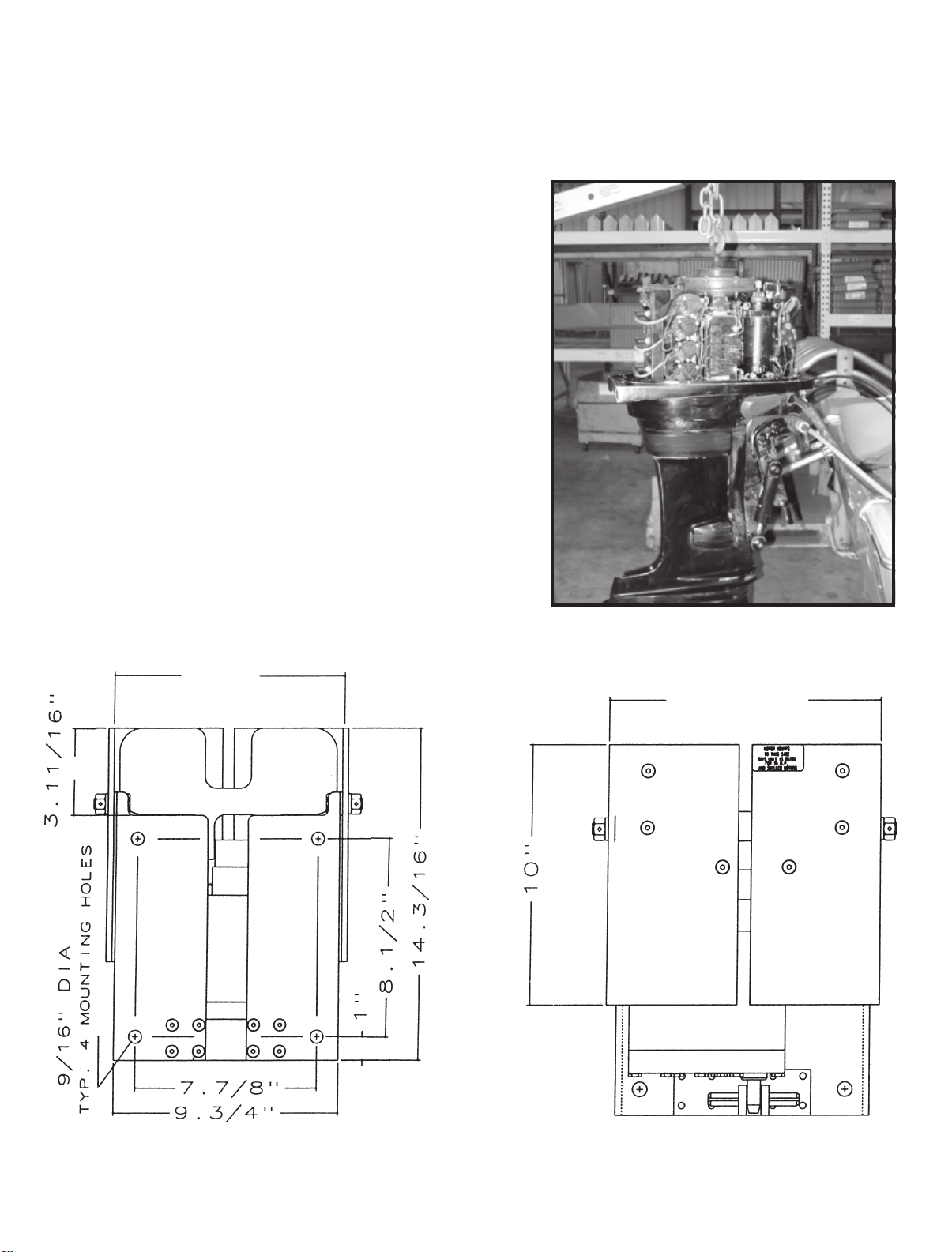
Step 1: Consult the outboard motor manual for the proper motor
lifting procedures. You will need to lift the motor in some
fashion with a lifting device rated at the proper lifting
capacity.
Step 2: Attach the lifting device to the motor making sure the
motor is supported safely.
Step 3: Remove the fasteners that mount the motor to the tran-
som of the boat.
Step 4: Swing the motor away from the transom of the boat tak-
ing care not to damage any wires or cables (Fig. 1).
The figures below show the transom view (Fig. 2) and the motor
view (Fig. 3) of the PT-35. The transom view to be mounted to the
transom and the motor view to the motor.
Fig. 2
11”
Fig. 1
Fig. 3
11.1/2”
TRANSOM VIEW MOTOR VIEW
- 1 -- 8 -
Page 4

MOUNTING THE PT-35 POWER TILT & TRIM
TO THE TRANSOM OF THE BOAT
When mounting your motor, take into consideration
that your motor will set back away from the transom
5 1/2
inches. This allows you to mount your motor higher
than you can when it is mounted to the transom (because as the water passes under the transom it comes
up toward the propeller when it is set back 5
When mounting the motor on the PT-35, the cavitation
plate of your motor should be 1 to 3 inches above the
bottom of the boat for best performance results.
NOTE: If you have a lightweight boat and cavitation
occurs at the prop when you walk from the stern to
the bow, you might consider distributing the weight
in the boat toward the back.
Step 5: Fill in any motor mounting holes in the tran-
som with silicone rubber sealant. Drill four holes
into the transom to match the four predrilled
holes that are on the transom side of the tilt
and trim (Fig. 4). When drilling the holes, make
sure that the top of the transom side of the
PT-35 will be approximately 1" above the top of
the transom and that it is centered on the transom as shown in Fig. 6.
1/2
inches).
Fig. 4
NOTE: To make the mounting holes more accessible,
follow the instructions on page 4 to obtain power to
the PT-35. Tilt the PT-35 up to allow access to the
mounting holes.
1/2
Step 6: Use at least
the PT-35 to the transom. To ensure proper
clearance, insert the mounting bolts from the
inside of the PT-35 out (the head of the bolt inside of the PT-35 and the nut and washers on
the inside of the boat). Fasten the unit to the
transom, making sure to use flat washer and
lock washer before the nut (Fig. 5 & 6). These
bolts should be checked for tightness frequently.
" stainless steel bolts to mount
MOUNTING AN OUTBOARD MOTOR
WITH TRANSOM CLAMPS TO THE PT-35
Step 7: Set your motor onto the PT -35 and center it. (If
your motor is mounted with four bolts through
the transom and does not have transom clamps,
go to Step 10. Tighten the clamps down as shown
in Fig 7.
Fig. 5
Fig. 7 Fig. 6
Page 5
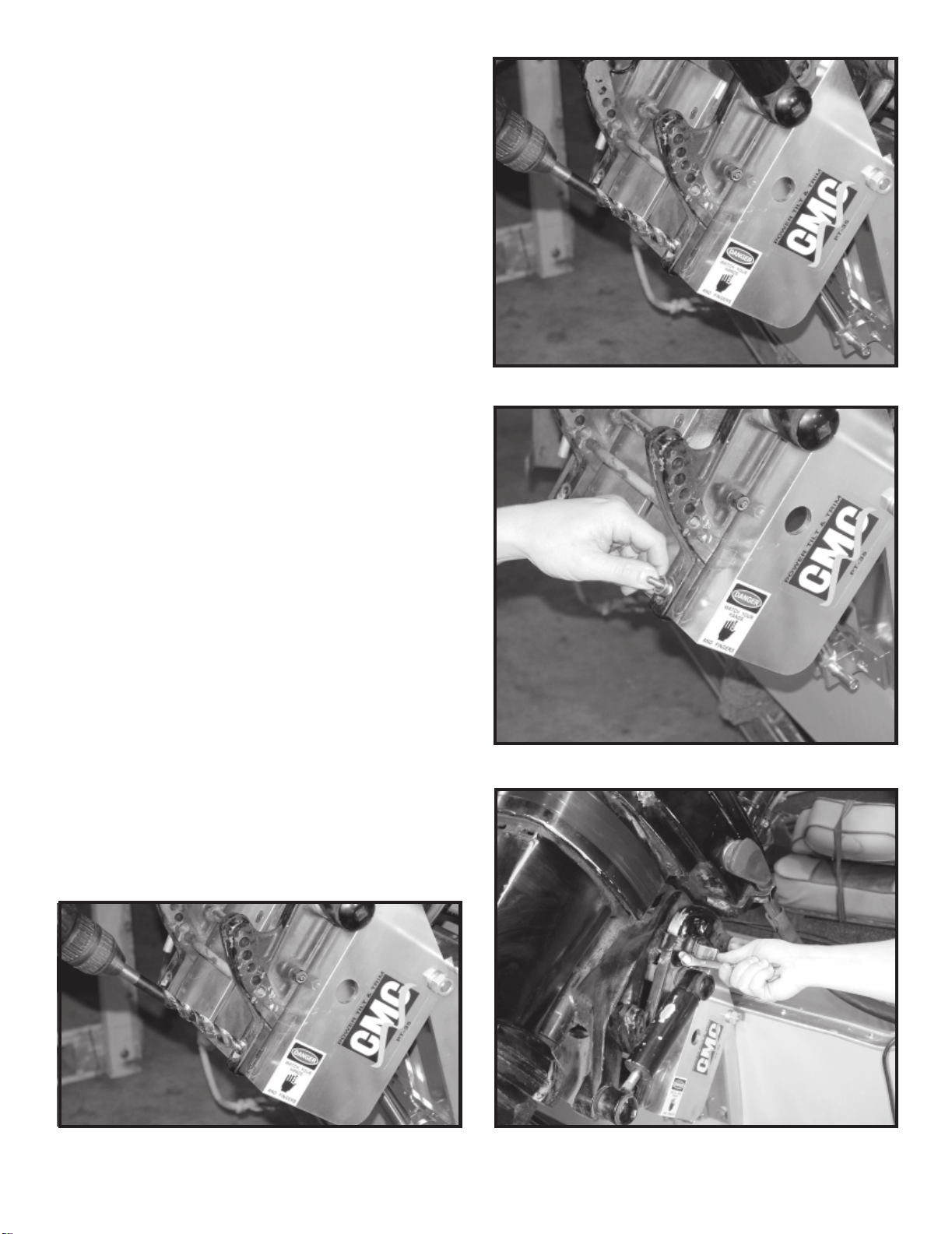
Step 8: If your motor has two mounting bolts at the
bottom, using the mounting holes as a template,
drill through the PT-35 as shown in fig. 8.
CAUTION: SO THAT YOU WILL NOT ACCIDENTALLY
DRILL INTO THE ACTUATOR, TILT THE PT-35 AS
SHOWN IN Fig 8.
Step 9: Use at least 1/2” stainless steel bolts to mount
the motor to the PT-35. To ensure proper clearance, insert the motor mounting bolts from the
inside out (the head of the bolt inside of the PT35 and the nut, flat washer and lock washer on
the outside). Tighten the bolts. These should be
checked frequently for tightness (Fig. 9).
CAUTION: When you run your boat for the first time
after you have installed the PT-35, make sure that
you have plenty of water pressure at top end speed.
If the water pressure is less than it was before the
PT-35 was installed, lower the motor.
NOTE: The PT-35 has a total of 84 degrees of tilt and
trim. Some motors will not be able to tilt the full 84
degrees without the cowling or motor clamps interfering with the transom of the boat. Exercise caution
when tilting to see if there are any limitations.
Most steering cables have plenty of extra length to
install the motor to the PT-35 without disconnecting
them. However, some models may require longer
steering cables.
Fig. 8
MOUNTING AN OUTBOARD MOTOR THAT DOES
NOT HAVE TRANSOM CLAMPS
Step 10: Set the motor onto the PT -35 and center it.
Using the motor as a template, mark the location of the required top two holes to be drilled
for mounting the motor. Drill the holes at the
top first and mount the motor using at least
1/2” stainless steel bolts, To ensure proper
clearance, insert the mounting bolts from the
inside of the PT-35 out (the head of the bolt
inside of the PT-35 and the nut and washers
on the outside). Tighten the bolts (Fig. 10). Drill
the lower mounting holes using the motor as
a template (Fig. 11). When you drill the lower
hole on the port side, make sure your tilt the
motor enough to eliminate the chance of accidentally drilling into the actuator.
Fig. 9
- 3 -
Fig. 10Fig. 11
Page 6
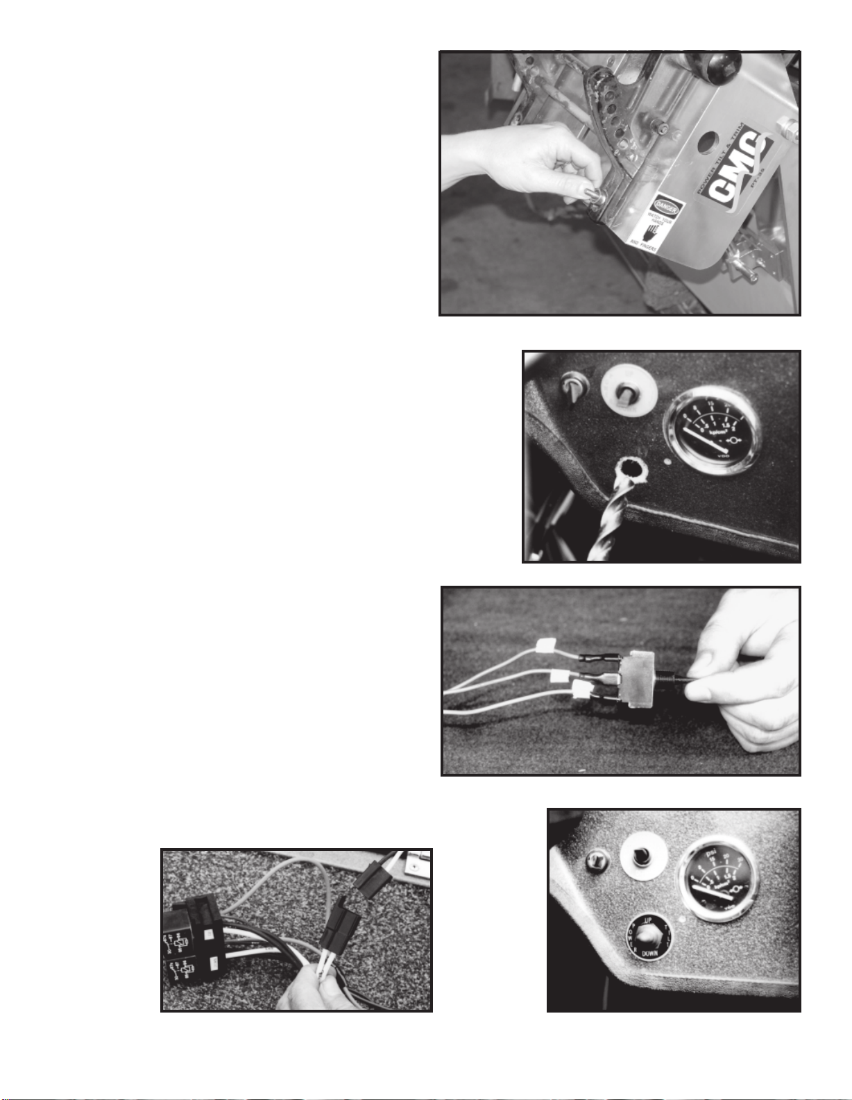
Tighten the lower bolts (Fig. 12). All of the mounting
bolts should be checked for tightness frequently.
CONNECTING TO POWER SOURCE
Step 11: Find a good location for the up-down toggle
switch. This toggle switch should be located
for easy access while operating the throttle.
Use a 1/2 inch drill to drill a hole at the chosen location taking care not to damage wires
or brackets (Fig. 13)
Step 12: Locate the wires on the wire assemble; 1. One
labeled up; 2. One labeled down; 3. One labeled 12V. Position the switch so the terminal
posts are on the side nearest you. Connect the
down wire terminal to the top post. Connect
the 12V wire terminal to the center post. Connect the up wire terminal to the bottom post
(Fig. 14).
Step 13: Push the toggle switch through the 1/2 inch
hole that you previously drilled. Place the updown switch plate and rubber boot with nut
on the switch (Fig. 15).
Step 14: Connect the 2-wire male connector from the
hydraulic power unit to the female 2-wire connector at the end of the wire assembly
(Fig. 16).
Find a dry location for the two 40 amp relays and se-
cure them there.
NOTE: If your boat is used in a corrosive environment such as saltwater and you cannot locate a dry
place for the relays, you can secure the relays inside
the cowling of your engine. Instead of connecting the
positive and negative ring terminals of the wire assembly to the battery, connect them to the starter
where the positive and negative leads from the battery are attached.
Step 15: Connect the ring terminal labeled POS to the
positive battery terminal and connect the ring
terminal labeled NEG to the negative battery
terminal.
The PT-35 is now ready for operation. When you push
the toggle switch lever up, the PT-35 should run up. When
you push the switch down, it should run down.
CAUTION: WHEN TRAILERING IT IS RECOMMENDED
TO SUPPORT THE PT-35 WITH A TRANSOM SAVER
DEVICE. WHEN RUNNING THE PT-35 DOWN TO THE
SUPPORT, JUST MAKE CONTACT WITH IT. DO NOT
CONTINUE TO LUG IT DOWN AFTER INITIAL CONTACT HAS BEEN MADE OR DAMAGE TO THE, PT-35
WILL OCCUR.
Fig. 12
Fig. 13
Fig. 14
Fig. 16
Fig. 15 Fig. 18
- 4 -
Page 7
SERVICING
Your CMC PT-35 is operated with a hydraulic actuator, which is located inside the unit. It is filled with the
correct amount of hydraulic fluid and tested at the factory. If it becomes necessary to add fluid to the actuator,
use #2216 Mystic or equivalent, SAE 20 or 30 non-detergent oil. Follow the procedure below for adding fluid
and bleeding the system:
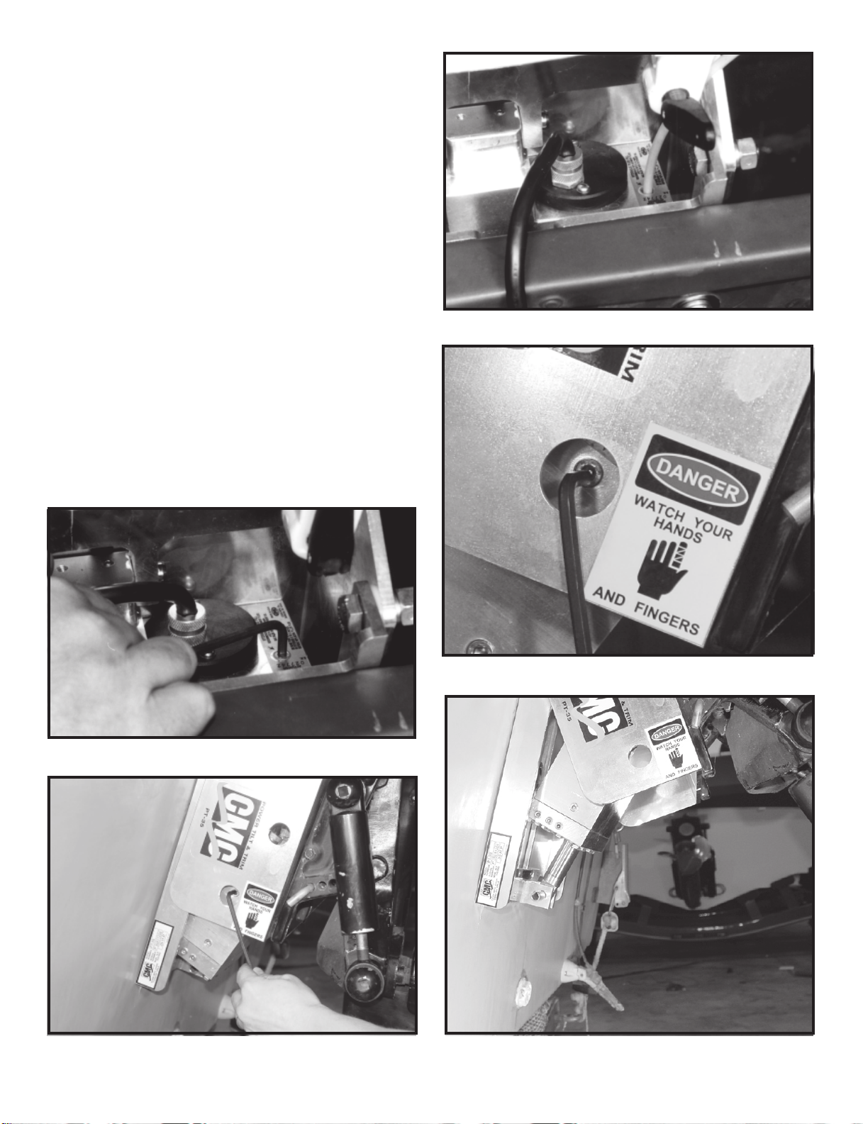
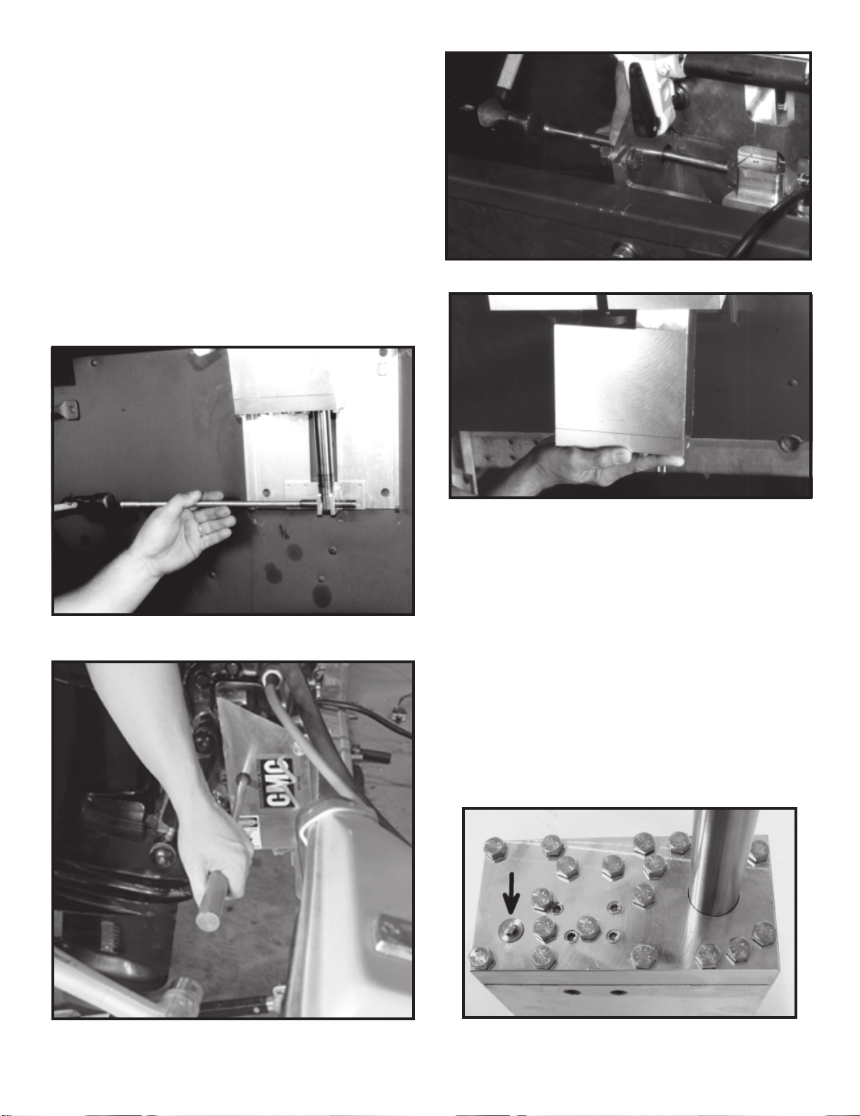
First, trim the PT-35 all of the way down. Remove the
1/8" brass socket filler plug with a 3/16" hex key wrench
(Fig. 17). Next, with the same wrench, remove the level
plug. You can access this plug through the lower machined hole on the port side motor rail as shown in Fig.
18. Pour fluid into the actuator through the filler hole
until fluid runs out of the level hole on the side of the
actuator (Fig. 19). Run the actuator until the ram is fully
extended and the motor bogs down (the PT-35 is all the
way up). Then retract the ram completely until the motor bogs down (trim the PT-35 all the way down). Replace the level plug (Fig. 20). Tilt the PT-35 out until the
ram is extended 2 to 3 inches out of the actuator
(Fig. 21).
Replace the filler plug.
If preferred, the above procedure can be executed with
the actuator completely remove from the PT-35. Please
see the next page for the removal of the actuator.
Fig. 19
Fig. 17
Fig. 20
Fig. 21
- 5 -
Page 8
ACTUATOR REMOVAL
There are holes machined in the port and starboard
motor rails to allow easy access with a 1/2" to 7/16"
diameter punch or driver bar for removal of the two actuator spring pins. One spring pin is located at the top of
the actuator and the other is located at the bottom of the
ram.
Trim the PT -35 down. Follow the electrical cordset from
the motor of the actuator into the boat approximately
6 ft. to a male to female connection, Disconnect it there.
Next, drive the spring pin at the bottom of the ram out
with your punch or driver bar (Fig. 22). Then, insert the
driver bar or punch through the machined hole on the
port or starboard motor rail to the spring pin at the top
of the actuator and drive the pin out (Fig. 23 & 24).
Remove the actuator from the bottom of the PT-35
(Fig. 25).
Fig. 24
Fig. 22
Fig. 25
EMERGENCY RELIEF VALVE
Your PT-35 actuator features a pressure relief valve
that will allow you to manually raise or lower the tilt &
trim unit if it becomes necessary due to power loss or
actuator malfunction. This pressure relief valve is a 1/4
hex screw head located at the bottom of the actuator
toward the port side (Fig. 26). Gradually turn the relief
valve counter clockwise l/2 to 1 full turn (NO MORE THAN
1 FULL TURN). This will allow you to manually raise or
lower the PT-35.
CAUTION: IF THE PT-35 IS IN THE UP POSITION
WHEN IT BECOMES NECESSARY TO RELIEVE THE
PRESSURE IN THE SYSTEM, FIRST SUPPORT THE
UNIT WITH A HOIST OR THE AID OF ANOTHER PERSON. RELIEVE THE PRESSURE AND SLOWLY LOWER
THE UNIT. EXERCISE CAUTION TO AVOID INJURY.
Fig. 23
Fig. 26
- 6 -
Page 9
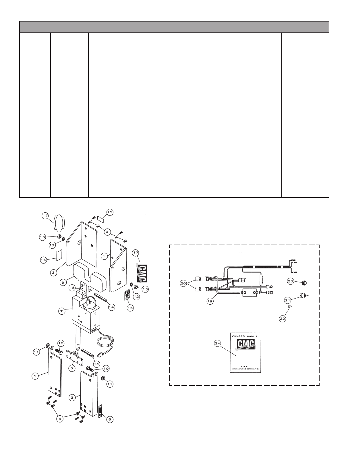
ITEM #52100 PT-35 POWER TILT AND TRIM® PARTS LIST
ITEM# PART # DESCRIPTION QTY. REQ.
__________________________________________________________________________________________
__________________________________________________________________________________________
1 52010 PORT SIDE MOTOR RAIL 1
__________________________________________________________________________________________
2 52020 STARBOARD SIDE MOTOR RAIL 1
__________________________________________________________________________________________
3 52030 PORT SIDE TRANSOM RAIL 1
__________________________________________________________________________________________
4 52040 STARBOARD SIDE TRANSOM RAIL 1
__________________________________________________________________________________________
5 52050 TOP CLEVIS BRACKET 1
__________________________________________________________________________________________
6 52060 BOTTOM CLEVIS BRACKET 1
__________________________________________________________________________________________
7 7050 MODEL 7050 HYDRAULIC ACTUATOR ASSEMBLY 1
__________________________________________________________________________________________
8 52130 SERIAL NUMBER TAG 1
__________________________________________________________________________________________
9 52070 1/4” - 20 X 1/2” FLAT HEAD CAP SCREWS 18-8 S.S. 14
__________________________________________________________________________________________
10 52150 1/2” -13 X 1-1/4” HEX HEAD CAP SCREW 18-8 S.S 2
__________________________________________________________________________________________
11 52120 1/8” X 1/2” X 1” NATURAL NYLON FLAT WASHER 2
__________________________________________________________________________________________
12 6036 1/2” HELICAL SPRING LOCK WASHER 18-8 STAINLESS STEEL 2
__________________________________________________________________________________________
13 7080 1/2” -13 TWO WAY SELF LOCKING HEX NUT 18-8 S.S. CAD PLATED 2
__________________________________________________________________________________________
14 6009 1/2” X 3-1/2” SPRINT PIN S.S. 2
__________________________________________________________________________________________
15 52140 WARNING STICKER FOR PT-35 1
__________________________________________________________________________________________
16 51222 WATCH YOUR HANDS WARNING LABEL 2
__________________________________________________________________________________________
17 52202 TILT AND TRIM DECAL 2
__________________________________________________________________________________________
18 6083 1/4” - 20 x 3/16” HEX SOCKET CUP OINT SET SCREW 18-8S.S. 1
__________________________________________________________________________________________
19 7014 MAIN WIRE HARNESS FOR P.M. MOTOR 1
__________________________________________________________________________________________
20 7122 RELAY 2
__________________________________________________________________________________________
21 7123 TOGGLE SWITCH 1
__________________________________________________________________________________________
22 7124 TOGGLE SWITCH RUBBER BOOT 1
__________________________________________________________________________________________
23 51380 TOGGLE SWITCH PLATE 1
24 52160 PT-35 OWNERS MANUAL 1
- 7 -- 2 -
Page 10
TROUBLESHOOTING
If problems should occur, follow the checklist below step by step. This should eliminate any simple problems that
should arise.
PROBLEM:
The unit will not run in either direction. 1. Check for dead battery.
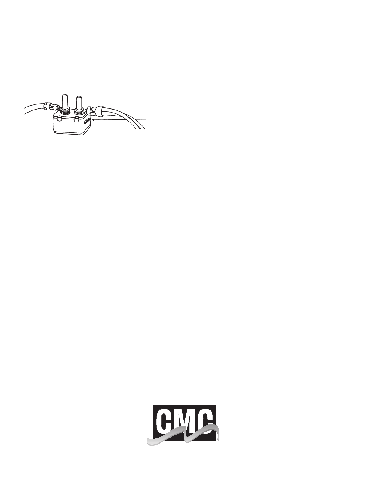
2. Reset the circuit breaker at + battery terminal.
3. Check continuity through toggle switch.
4. Check wire continuity from switch to connector.
5. Check for 12 volts at toggle switch, wire labeled +.
CIRCUIT BREAKER RESET BUTTON
6. If these check well, replace the hydraulic actuator.
Will not run in one direction.
Actuator runs but unit does not move up
or down.
Unit at up position leaks down to the bottom.
Unit at up position and will not
come down.
Unit will not trim under power or
goes up very slowly while not under power.
1. Check the toggle switch.
2. Check wire continuity from toggle switch to connector.
1. Check hydraulic fluid level.
1. Run unit up and down several times. Could have debris in check
valve. If this does not correct the problem replace actuator.
1. Make sure there is no foreign object binding the unit. If there is
no foreign object binding the unit, replace the actuator.
1. Check with ammeter on + line to see if registering 50 - 60 amps
when unit is run to top and is “bogged” down. (Unit will pull 25
- 40 amps during up and down motion).
2. If a smaller gauge wire has been spliced into wire harness, this
could be the cause.
3. Check with voltmeter to see if getting 12 volts from battery.
Also check it as the PT-35 is running. If voltage drops more
than 1 volt, the battery is not supplying enough power.
4. If the actuator “free wheels” and does not leak down, the system is low on fluid or has air in system. See servicing, page 5 for
instructions to refill and bleed air.
Unit is in the down position and
“locked up” (bogging down).
1. Turn the emergency relief valve (see page 6) counter clockwise
1/2 turn to open. Run the switch up for 5 seconds then down
for 5 seconds. Close the emergency relief valve by turning it
back 1/2 turn clockwise. Now run the switch up and down.
The PT-35 should now raise and lower.
Page 11

LIMITED WARRANTY
New CMC PT-35 Power Tilt & Trim units are warranted by the manufacturer for one year from date of purchase against defects in workmanship
and/or materials in the hydraulic system and five years from the date of
purchase against defects in workmanship and/or material in the structure.
This warranty means that only the parts that prove defective during the
period of warranty will be repaired or replaced at our option. Cook Manufacturing Corporation will accept only parts returned for warranty prepaid from initial purchaser and return the repaired or replaced parts
freight collect.
Avoid tampering with the Hydraulic Actuator, if a warranty claim is to be
made. The warranty is void on any hydraulic actuator returned that shows
signs that it has been dismantled or electrical cordset from the motor has
been cut.
A return authorization number must be issued from the factory prior to
the return of defective parts. Call toll free in the continental United States
1-800-654-3697; outside the United States Call 580-252-1699 to obtain
the return authorization.
There are no warranties which extend beyond the description on the face
hereof. No one has authority to make any representations concerning the
operation of CMC Power Tilt & Trim units except those made in writing
by Cook Manufacturing Corporation.
This warranty does not apply for any racing applications or if damage
occurs because of accident, improper handling or operation, abuse or
misuse.
All liability for any incidental or consequential damage is expressly excluded herefrom.
In order to obtain the benefit of this warranty and agreement, the warranty card found in the centerfold of this manual must be completely
filled out and mailed within 30 days to Cook Manufacturing Corporation.
This warranty applies to original ownership only.
Page 12

acknowledgement
COOK MANUFACTURING CORPORATION
3920 SOUTH 13TH • DUNCAN, OKLAHOMA 73533
(580) 252-1699
 Loading...