

CMA Dishmachines AHB, AHS, AHC, Scullery, B Owner's Manual
...
Owner’s Manual
Keep with machine for reference
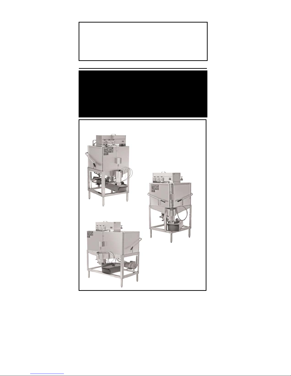
MODELS AH/B/C/S
INSTALLATION & OPERATION
Rev 1.00 B
CMA DISHMACHINES
12700 KNOTT STREET
GARDEN GROVE, CALIFORNIA 92841
800-854-6417
FAX 714-895-2141

TABLE OF CONTENTS
MODEL AH/B/C/S.
1. SPECIFICATIONS ........................................................................................ 3
1.1 MODEL AH/C......................................................................................................................................3
1.2 MODELS B/B ENERGY SAVER ............................................................................................................4
1.3 AH, B AND C OPERATIONAL CYCLE...................................................................................................5
2. GETTING STARTED..................................................................................... 7
2.1. INTRODUCTION TO MODELS AH, B ,C&” S” SERIES...........................................................................7
2.2. RECEIVING AND INSTALLATION...........................................................................................................8
2.2.1. Electrical ....................................................................................................................................8
2.2.2. Plumbing.....................................................................................................................................8
2.2.3. Connecting the Scrap Accumulator and Drain...........................................................................9
2.2.4. Installer’s Checklist....................................................................................................................9
3. OPERATION............................................................................................... 10
3.1. INITIAL SETUP ...................................................................................................................................10
3.1.1. Check….....................................................................................................................................10
3.1.2. Filling the Machine...................................................................................................................10
3.1.3. Chemicals .................................................................................................................................10
3.1.4. Run a Cycle...............................................................................................................................10
3.2. GENERAL...........................................................................................................................................11
3.3. ADDENDUM FOR MACHINES INSTALLED IN THE CITY OFCHICAGO....................................................12
3.4. ELECTRICAL DIAGRAMS....................................................................................................................13
3.4.1. Models AH/ C & B....................................................................................................................13
3.4.2. Solid Bowl.................................................................................................................................14

1. Specifications
,
Electrical and plumbing connections must be made by a qualified service person who will comply with all available
Federal
State, and Local Health, Electrical, Plumbing and Safety codes
1.1 Model AH/C
WATER CONSUMPTION
USA METRIC
PER RACK 1.7 GAL. (6.45 L)
PER HOUR 74 GPH (280.1 LPH)
OPERATING CYCLE
WASH TIME-SEC. 45 45
RINSE TIME-SEC. 30 30
DWELL TIME-SEC. 15 15
TOTAL CYCLE 90 SEC.* 90 SEC.*
*Other cycle times are available
OPERATING CAPACITY
RACKS PER HOUR (NSF Rated) 40 40
WASH TANK CAPACITY 1.7 GAL. (6.45 L)
PUMP CAPACITY 52 GPM (197 LPM)
WATER REQUIREMENTS
REQUIRED MINIMUM TEMP. 120°F (49°C)
RECOMMENDED TEMP. 140°F (60°C)
WATER INLET ¾” 1.9cm
DRAIN CONNECTION 2” 5.1cm
DIMENSIONS
DEPTH 25 ¾” (65.4cm)
WIDTH 25 ¾” (65.4 cm)
HEIGHT 56-57” (142-144.8cm)
HEIGHT (SCULLERY) 66”-67” (168-170 cm)
MAX CLEARANCE FOR DISHES 17”
MAX CLEARANCE FOR DISHES (S) 27”
(43.18 cm)
(68,58”cm)
STANDARD TABLE HEIGHT 34” (86.36 cm)
STANDARD DISH RACKS 19 ¾” x 19 ¾” (50 x 50 cm)
ELECTRICAL RATING
VOLTS
(60-Hz)
115
AMPS
16
WASH PUMP MOTOR 1 HP
SHIPPING WEIGHT
APPROXIMATE 270# (122.5 kg)
APPROXIMATE (SCULLERY) 295# (133.8 kg)
MODEL AH, B & C INSTALLATION & OPERATION MANUAL Rev. 1.01 Page
3

Electrical and plumbing connections must be made by a qualified service person who will comply with all available
,
Federal
State, and Local Health, Electrical, Plumbing and Safety codes
1.2 Models B/B Energy Saver
USA METRIC
WATER CONSUMPTION
PER RACK 1.5/ .96 GAL. (5.7/ 3.63 L)
PER HOUR 118.4/ 76.8 GP H (448/291 LPH)
OPERATING CYCLE
WASH TIME-SEC. 45 45
RINSE TIME-SEC. 30 30
DWELL TIME-SEC. 15 15
TOTAL CYCLE 90 SEC.* 90 SEC.*
*Other cycle times are available
OPERATING CAPACITY
RACKS PER HOUR (NSF Rated) 80 80
WASH TANK CAPACITY 3.0 GAL. (11.4 L)
PUMP CAPACITY (two pumps) 104 GPM (393.68 LPM)
WATER REQUIREMENTS
REQUIRED MINIMUM TEMP. 120°F (49°C)
RECOMMENDED TEMP. 140°F (60°C)
WATER INLET ¾” 1.9cm
DRAIN CONNECTION 2” 5.1cm
DIMENSIONS
DEPTH 25 ¼” (64 cm)
WIDTH 44 ¼” (112 cm)
HEIGHT 55 ½”-56 ½” (141-143.5
HEIGHT (SCULLERY) 65-66” (165-168cm)
MAX CLEARANCE FOR DISHES
MAX CLEARANCE FOR DISHES
(S)
STANDARD TABLE HEIGHT 34” (86.36 cm)
STANDARD DISH RACKS 19 ¾” x 19 ¾” (50 x 50 cm)
ELECTRICAL RATING
WASH PUMP MOTORS (2) 1 HP each
cm)
17”
27"
VOLTS
(60-Hz)
115
(43.18 cm)
(68,58cm)
AMPS
30
SHIPPING WEIGHT
APPROXIMATE 352# (160 kg)
APPROXIMATE (SCULLERY) 377# (171 kg)
MODEL AH, B & C INSTALLATION & OPERATION MANUAL Rev. 1.01 Page
4
1.3 AH, B and C Operational Cycle*
g
r
W
g
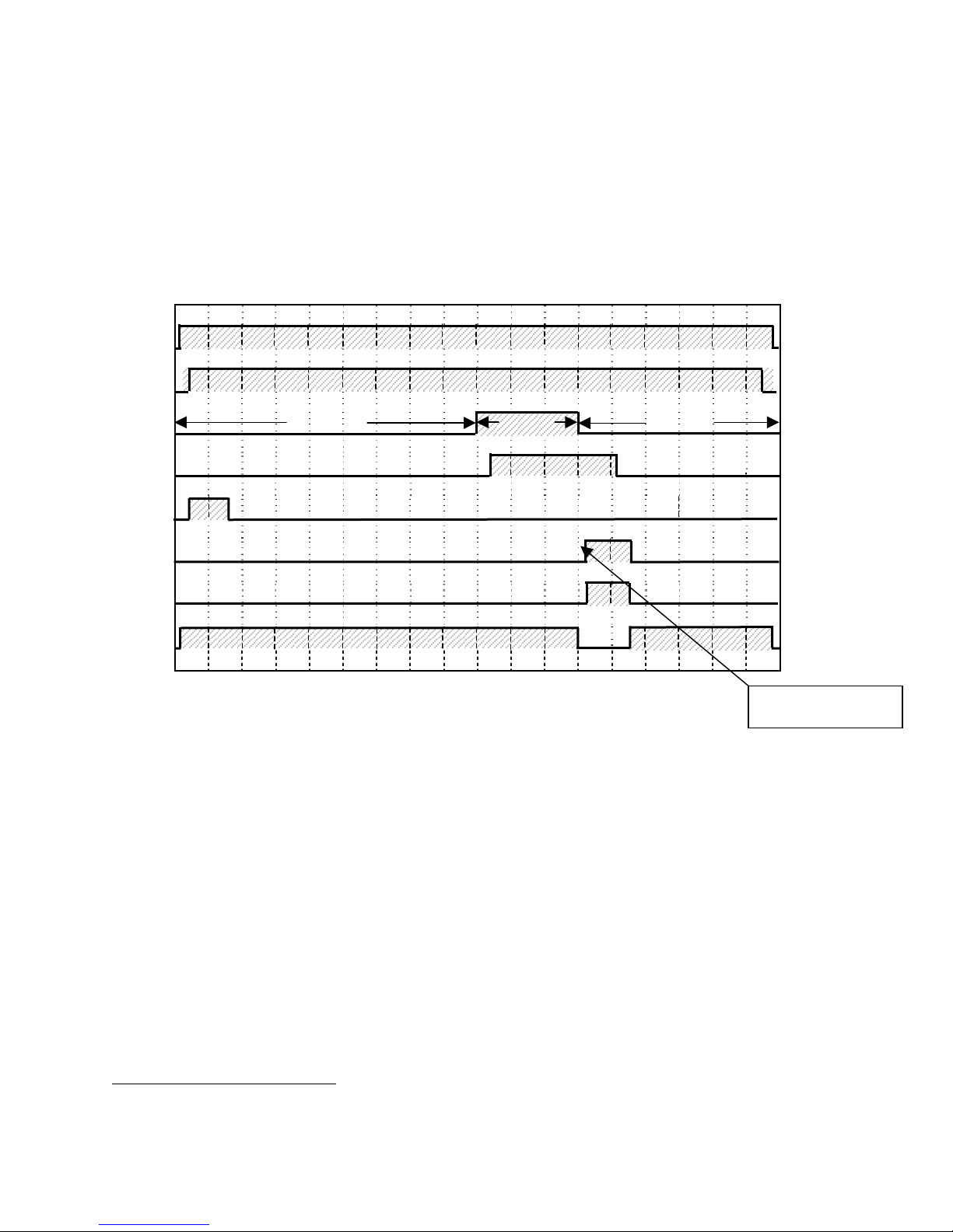
The AH, B and C Operational Cycle have a total cycle time of 90 seconds. The Timing
Diagram and the steps listed below detail the individual functions that are executed during
each Operational Cycle.
Seconds: 0 10 20 30 40 50 60 70 80 90
Cam 1
Cam 2
Cam 3
Cam 4
Cam 5
Cam 6
Cam 7
Cam 8
ASH
DRAIN
RINSE
Start/Stop
Cycle Reset
Drain/Rack
Counter
Flush/Fill
Deter
ent
Sanitize
Rinse Aid
Pump Motor
1. With the machine powered up, closing the doors begins a cycle.
4sec. delay to prevent
chemical dama
a) When the door closes the timer assembly motor is energized through the normally
closed contact of the Start/Stop Relay.
b) Within a couple of seconds cams 1 and 2 close their respective switches. Cam
switch 1 (Start/Stop) maintains power to the timer assembly motor throughout the
90-second cycle. Cam switch 2 (Cycle Reset) energizes the Start/Stop Relay.
c) The Start/Stop Relay, once it is energized by cam switch 2, is held in by its own
normally open contact for as long as the doors remain closed.
2. Cam switch 8 controls the pump motor. The pump motor comes ON at the beginning
of the operational cycle and continues to run until the end of the drain function
(controlled by cam switch 3), at which time it turns off for about eight seconds allowing
time for the machine to refill enough to avoid running the pump dry before the pump
motor restarts and runs to the completion of the operational cycle.
*
“S” series same otherwise noted
e
MODEL AH, B & C INSTALLATION & OPERATION MANUAL Rev. 1.01 Page
5
 Loading...