

Page 1
MODEL CMA-180UC
FAX 714-895-2141
CMA DISHMACHINES
PARTS MANUAL Re v 1.18B
12700 KNOTT AVENUE
GARDEN GROVE, CALIFORNIA 92841
800- 854- 6417
wwwcmadishmachines.com
Page 2

TABLE OF CONTENTS
MODEL CMA-180UC
1. PARTS MANUAL .......................................................................................... 3
1.1. INITIAL PARTS KIT (P/N 1100.66) .......................................................................................... 3
1.2. DRAIN PUMP .......................................................................................................................... 4
1.3. DRAIN PUMP REMOVAL INSTRUCTIONS ................................................................................. 5
1.4. MECHANICAL DRAWINGS ....................................................................................................... 6
1.4.1. Cabinet Assembly........................................................................................................... 6
1.4.2. Door Assembly ............................................................................................................... 7
1.4.3. Electrical Tray ............................................................................................................... 8
1.4.4. Control Box Assembly p/n 18611.61 .............................................................................. 9
1.4.5. Chemical Dispenser (Optional) ....................................................................................10
1.4.6. Plumbing System Assembly (Effective August 2012) ....................................................11
1.4.7. Plumbing System Assembly ...........................................................................................12
1.4.8. Drain System Assembly .................................................................................................13
1.4.9. Wash System .................................................................................................................14
1.4.10. Rinse System .................................................................................................................15
1.4.11. S/S Pump Assembly (Effective August 2009) ................................................................16
1.4.12. Pump System Assembly .................................................................................................17
1.4.13. Old Heater Assembly (Square Flange) .........................................................................18
1.4.14. New Heater Assembly (Triangular Flange) ..................................................................19
1.4.15. Drain Valve...................................................................................................................20
1.4.16. Drain Valve (Effective January 2011) ..........................................................................21
wwwcmadishmachines.com
Page 3
1. Parts Manual
1.1. Initial Parts Kit (P/N 1100.66)
P/N DESCRIPTION Qty
15504.00 Motor Contactor, 2-Pole 20 Amp 1
15504.50 Heater Contactor, 2-Pole 35 Amp 1
00501.00 2-Minute Timer Motor 1
00631.00 Ice Cube Relay 120 V 1
15523.00 Rocker Switch Start Momentary 1
15523.50 Rocker Switch Drain/Fill 1
15524.00 Rocker Switch Power Maintained 1
00556.10 Reed Switch 1
03623.00 1/2” Vacuum Breaker Repair Kit – Watts 1
04113.00 L1X/L1-C Drain Valve 120V 1
00206.30 Pump Seal Kit 1
13417.89 Heater Thermostat 1
17523.60 High Limit Switch 200°F 1
00411.00 Microswitch 1
03203.01 Dual Temperature Display Kit
00707.00 1/2 Water Solenoid Repair Kit JE
00738.15 Solenoid Coil JE115V/60Hz
Parts Manual
1
1
1
MODE L CMA-180UC PARTS MANUAL Rev. 1.18B Page 3
Page 4
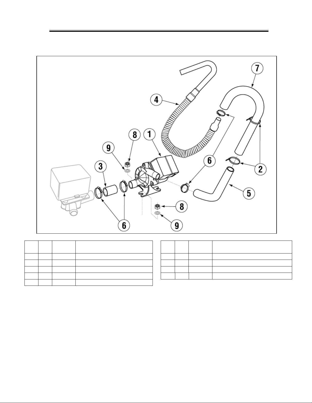
1.2. Drain Pump
Parts Manual
ITEM
NO.
NO.
REQ’D
1 1 15503.00 Drain Motor Ultra Jet for CMA-180UC 6 4 03101.00 Hose Clamp 1”
2 2 00932.50 Twist Tie 7 1 15603.00 Drain Line Gooseneck
3 1 15601.10 Black Drain Hose 1" ID X 3 1/2" 8 2 03801.10 10-32 SS Nut
4 1 15605.00 Drain Hose with Goose Neck 9 2 04806.00 #10 Brass Washer
5 1 15601.60 Robber Hose 90 Deg.
P/N DESCRIPTION
ITEM
NO.
NO.
REQ’D
P/N DESCRIPTION
MODE L CMA-180UC PARTS MANUAL Rev. 1.18B Page 4
Page 5
Parts Manual
purple and white
disconnect the wires
Remove this
hose clamp
Valve.
inch pump inlet
Remove drain hose from
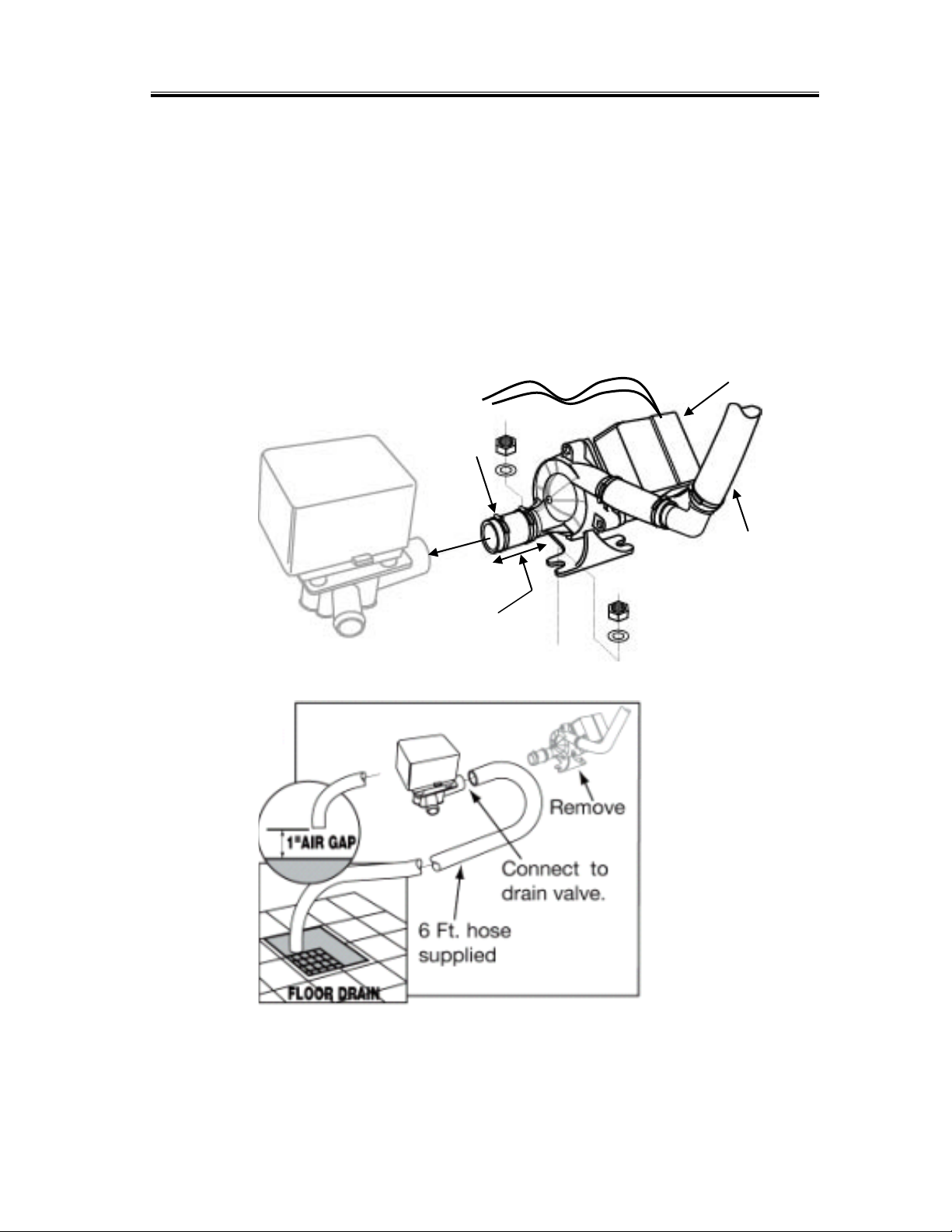
1.3. Drain Pump Removal Instructions
Drain Pump (P/N 15503.00) should only be used if a floor drain is not accessible to
the machine at installation.
When converting the UC-180 dishwasher to a gravity drain unit, remove the drain pump
assembly as shown in Figure 1. Re-route the 6Ft drain hose to the center port were the
drain pump was located, moving the displaced line to the open port of the valve. Insure
there is a 1” air gap between the discharge and floor drain as shown in Figure 2.
Disconnect
wires
over Drain
Remove this cover to
Disconnect 3-
drain hose.
Figure 1
the drain gooseneck
Figure
Figure 2.
MODE L CMA-180UC PARTS MANUAL Rev. 1.18B Page 5
Page 6
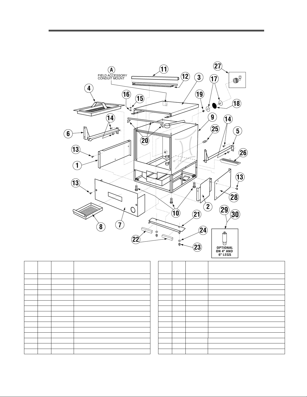
1.4. Mechanical Drawings
1 1 14502.82
Side Panel L.H. for CMA-180UC
16 4 00940.51
#10 Internal Lock Star Washer
2 1 14508.10
Peri Pump Front R Side Cover(180-UC)
17 1 01513.00
Detergent Injection Hole Plug
4 1 14510.00
Scrap Basket for CMA-180UC
19 1 00912.00
1/4”-20 Nylon Lock Nut
5 1 14511.00
Tray Track R.H. for CMA-180UC
20
2ft
03705.84
Control Box Gasket for CMA-180UC
7 1 14515.00
Lower Front Panel for CMA-180UC
22 2 00557.80
Magnet for CMA-180UC
8 1 14560.00
Scrap Tray Drawer for CMA-180UC
23 2 00927.00
8-32 Lock Nut
10 4 01310.60
Leg Adjusters for CMA-180UC *
25 1 00214.30
1/4" Compression x 3/8” MIP Fitting
11 1 14506.50
Door Gasket for CMA-180UC
26 1 14561.00
Scrap Trap Filter (CMA 180-UC)
13 6 00940.50
10-32 x 3/8 Trusshead Screw
28 1 14508.20
Peri Pump Back R Side Cover(180-UC)
14 8 00941.00
10-32 x 5/8 Panhead Screw
29 4 01147.50
Leg 4" 1/2-13 1" Diameter (UC)
15 4 03801.00
10-32 Lock Nut
30 4 01147.00
^Leg 6" 1/2"-13 1" Diameter (UC)
1.4.1. Cabinet Assembly
Parts Manual
ITEM
NO.
NO.
REQ’D
3 1 14503.50 SS Top for CMA-180UC 18 1 00752.00 Detergent Injection Hole Plug Gasket
6 1 14512.00 Tray Track L.H. for CMA-180UC 21 1 14558.00 Body Magnet Holder for CMA-180UC
9 1 14501.20 SS Body for CMA-180UC 24 2 04806.00 #10 Brass Flat Washer
12 1 14506.45 Gasket Bracket for CMA-180UC 27 1 03415.00 Chemical Bulk Head
P/N DESCRIPTION
MODE L CMA-180UC PARTS MANUAL Rev. 1.18B Page 6
ITEM
NO.
NO.
REQ’D
P/N DESCRIPTION
Page 7
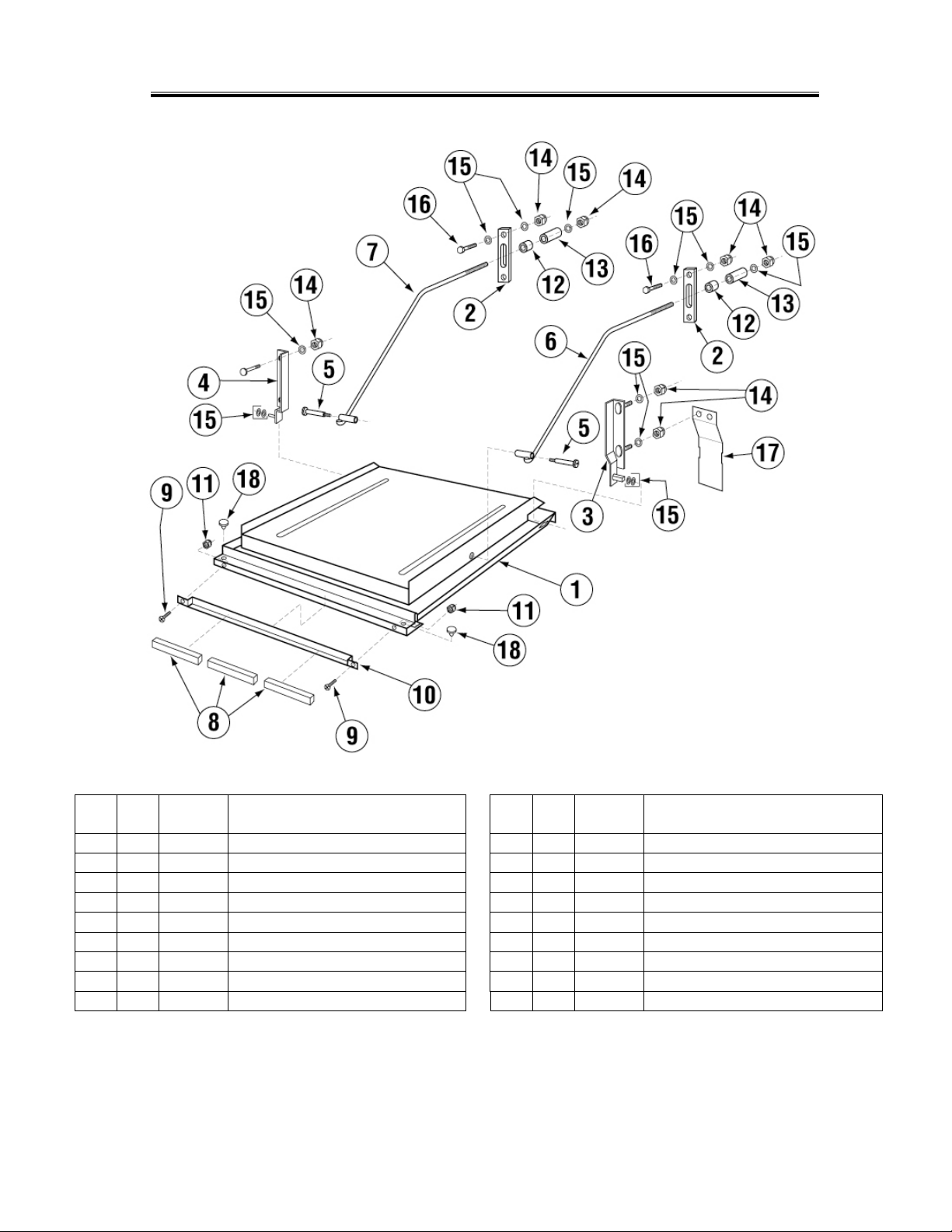
1.4.2. Door Assembly
Parts Manual
ITEM
NO.
NO.
REQ’D
1 1 14506.00 Door for CMA-180UC 10 1 14558.61 Door Magnet Holder for CMA-180UC
2 2 04517.60 Door Support Rod Block 11 2 00965.00 6-32 Lock Nut
3 1 14570.00 Door Hinge R.H. for CMA-180UC 12 2 00605.20 Door Rod Spacer
4 1 14570.50 Door Hinge L.H. for CMA-180UC 13 2 04517.15 Door Stop (Parallel)
5 2 04919.00 Door Rod Screw Pin for CMA-180UC 14 10 00912.00 1/4”-20 Nylon Lock Nut
6 1 04918.60 Door Support Rod Right 15 14 00924.00 1/4” SS Washer
7 1 04919.50 Door Support Rod Left 16 4 00914.10 1/4”-20 x 5/8” Hexhead Bolt
8 3 00557.80 Door Magnet 17 2 14518.00 Splash Guard
9 2 00970.60 6-32 x 1/2” Flathead Screw 18 2 00605.00 Door Handle Button-Undercounters
P/N DESCRIPTION
MODE L CMA-180UC PARTS MANUAL Rev. 1.18B Page 7
ITEM
NO.
NO.
REQ’D
P/N DESCRIPTION
Page 8

1.4.3. Electrical Tray
2 1 14408.81
Timer 2Min 5 Cam 180-UC S.T
9 1 13426.60
Ground Block
3 1 15504.00
Motor Contactor, 2-Pole 20 Amp
10 2 00965.00
6-32 Lock Nut
5 1 15520.50
Power Block, 3-Position
12 9 00400.85
3/4” Conduit, Sealtite
6 2 00438.00
Snap Bushing, Universal
13 1 13304.61
HT Plumbing Bracket
Parts Manual
ITEM
NO.
NO.
REQ’D
1 1 14504.00 Electrical Tray for CMA-180UC 8 12 00927.00 8-32 Nylon Lock Nut
4 1 15504.50 Heater Contactor, 2-Pole 35 Amp 11 1 00401.85 3/4” Conduit Connector, Straight
7 2 01001.00 6-32 x 1” Panhead Screw
P/N DESCRIPTION
ITEM
NO.
NO.
REQ’D
P/N DESCRIPTION
MODE L CMA-180UC PARTS MANUAL Rev. 1.18B Page 8
Page 9

Parts Manual
1.4.4. Control Box Assembly p/n 18611.61
ITEM
NO.
NO.
REQ’D
1 1 15520.00 Power Block 12-Position 12 2 00965.00 6-32 SS Nylon Lock Nut
2 2 00631.00 Ice Cube Relay 120 V 13 5 00927.00 8-32 Nylon Lock Nut
3* 1 03203.01 Dual Temperature Display Kit 14 6 00911.00 8-32 x 1/2” Panhead Screw
4 1 03202.60 Thermometer Transformer 15 1 00556.10 Reed Switch
5 1 14503.00 Control Drawer for CMA-180UC 16 4 00917.00 8-32 PM Nut
6 1 15523.00 Rocker Switch Start Momentary * 17 2 03705.82 Sponge Strip
7 1 15523.50 Rocker Switch Drain/Fill DPDT/Mom. * 18 2 03202.66 Thermocouple
8 1 15524.00 Rocker Switch Power Maintained * 19 2 00971.10 4-40 Nylon Lock Nut
9 1 13426.50 Ground Block 20 1 03485.00 Switch Guard (Undercounter)
10 1 00438.00 Snap Bushing, Universal 21 1 06232.61 CMA180-UC Panel Label
11 2 01001.00 6-32 x 1” Panhead Screw
P/N DESCRIPTION
ITEM
NO.
NO.
REQ’D
P/N DESCRIPTION
MODE L CMA-180UC PARTS MANUAL Rev. 1.18B Page 9
Page 10

Parts Manual
1 2 00816.00
Peri Pump Gear Motor (GL-C/GW -100)
8 4 13826.47
4-40 x 3/16 Phil Pan Head Screw
2 2 00818.00
GL-C/GW-100 Peri Pump Cartridge
9 4 00820.06
Circuit Board Standoff
4 2 00815.00
GL-C Peri Pump Complete
11 2 13826.00
4-40 X 5/8 Pan Head Screw
5 1 00821.00
GL-C/GW-100 Transformer
12 2 00820.50
Circuit Board Stand-off Bushing
6 2 00820.20
Circuit Board Connector
13 2 00971.10
4-40 Nylon Lock Nut
7 2 00820.00
GL-C/GW-100 Peri Pump Circuit Board
14
1
14508.00
UC180 Peri Pump Box
1.4.5. Chemical Dispenser (Optional)
ITEM
NO.
NO.
REQ’D
3 2 00839.00 GL-C/GW-100/UC180 Sqz Tube w/ Con. 10 4 00820.07 Circuit Board Standoff Cap
P/N DESCRIPTION
ITEM
NO.
NO.
REQ’D
P/N DESCRIPTION
MODE L CMA-180UC PARTS MANUAL Rev. 1.18B Page 10
Page 11

Parts Manual
1.4.6. Plumbing System Assembly (Effective August 2012)
ITEM
NO.
NO.
REQ’D
1 1 15602.00 SS Braided Hose 20" 19 1 03623.00 1/2” Vac. Breaker Repair Kit – Watts
2 1 00798.00 SS Braided Hose 20" 20 2 03614.00 Nipple, Brass 1/2” Close
3 1 03604.50 Fitting with Flow Disk 21 1 03232.00 1/8” Male Plug
4 1 03604.10 SS Solenoid Valve Flow Disc 22 1 13669.45 SS Mixing Chamber CMA-180UC
5 1 03603.10 /2 Water Sol Valve JE115V/60Hz 23 1 00798.00 1/2” SS Braided Hose
6 4 00760.00 5/8” Compression x 1/2” MIP Adapter 24 2 00915.00 1/4”-20 SS Nut
7 1 03605.00 Plumbing tube CMA-180UC 25 2 00724.00 1/2” Compression x 1/2” MIP Adapter
8 2 00940.50 10-32 X 3/8 Truss Head Screw 26 1 13304.53 Long Support Bracket
9 2 03801.60 10-32 KEPS Lock Nut 27 1 00798.40 SS Braided Hose 12”
10 1 14508.60 Plumbing Bracket (180-UC) 28 1 13604.10 1/2 x 1/8 Bushing Brass
11 1 00786.00 Water Sol Plunger 'G' JE 3/4 &1/2 29 1 13605.45 Pressure Gauge for CMA-180UC
12 1 41062.00 1/2" Strainer Ball Valves * 30 1 00707.00 1/2 Water Solenoid Repair Kit JE
13 1 00214.60 1/4” Compression x 1/2” MIP FTG 31 1 13658.00 Inlet Check Valve
14 2 00743.10 1/2" T,FxFxF 32 1 41062.10 Ball Strainer
15 1 05007.60 Vacuum Breaker Line 33 1 03603.20 1/2” Water Solenoid Valve Bonnet
16 1 03624.00 1/2” Vacuum Breaker – Watts 34 1 00738.10 Solenoid Coil JE115V/60Hz
17 1 00739.50 Vacuum Breaker Cap, SS 35 1 00706.10 Solenoid JE Spring Only
18 1 03624.25 Vacuum Breaker Bonnet, Brass
P/N DESCRIPTION
ITEM
NO.
NO.
REQ’D
P/N DESCRIPTION
MODE L CMA-180UC PARTS MANUAL Rev. 1.18B Page 11
Page 12

Parts Manual
1.4.7. Plumbing System Assembly
ITEM
NO.
NO.
REQ’D
1 1 15602.00 SS Braided Hose 20" 17 1 00739.50 Vacuum Breaker Cap, SS
2 1 00798.00 SS Braided Hose 20" 18 1 03624.25 Vacuum Breaker Bonnet, Brass
3 1 03604.50 Fitting with Flow Disk 19 1 03623.00 1/2” Vac. Breaker Repair Kit – Watts
4 1 03604.10 SS Solenoid Valve Flow Disc 20 2 03614.00 Nipple, Brass 1/2” Close
5 1 03604.00 SS Water Solenoid Valve 1/2" 21 1 03232.00 1/8” Male Plug
6 4 00760.00 5/8” Compression x 1/2” MIP Adapter 22 1 13669.45 SS Mixing Chamber CMA-180UC
7 1 03605.00 Plumbing tube CMA-180UC 23 1 00798.00 1/2” SS Braided Hose
8 2 00940.50 10-32 X 3/8 Truss Head Screw 24 2 00915.00 1/4”-20 SS Nut
9 2 03801.60 10-32 KEPS Lock Nut 25 2 00724.00 1/2” Compression x 1/2” MIP Adapter
10 1 14508.60 Plumbing Bracket (180-UC) 26 1 13304.53 Long Support Bracket
11 1 03604.30 Dema Valve Repair Kit 1/2" 27 1 00798.40 SS Braided Hose 12”
12 1 41062.00 1/2" Strainer Ball Valves * 28 1 13604.10 1/2 x 1/8 Bushing Brass
13 1 00214.60 1/4” Compression x 1/2” MIP FTG 29 1 13605.45 Pressure Gauge for CMA-180UC
14 2 00743.10 1/2" T,FxFxF 30 1 41015.60 Water Solenoid Coil Only
15 1 05007.60 Vacuum Breaker Line 31 1 13658.00 Inlet Check Valve
16 1 03624.00 1/2” Vacuum Breaker – Watts 32 1 41062.10 Ball Strainer
P/N DESCRIPTION
MODE L CMA-180UC PARTS MANUAL Rev. 1.18B Page 12
ITEM
NO.
NO.
REQ’D
P/N DESCRIPTION
Page 13

1.4.8. Drain System Assembly
Parts Manual
ITEM
NO.
NO.
REQ’D
1 1 04113.00 Drain Valve 120V 3 2 15601.60 Hose 1” ID 14” Pump to Manifold
2 6 03101.00 Hose Clamp #16-1” 4 1 15601.10 Black Drain Hose 1" ID X 3 1/2"
P/N DESCRIPTION
ITEM
NO.
NO.
REQ’D
P/N DESCRIPTION
MODE L CMA-180UC PARTS MANUAL Rev. 1.18B Page 13
Page 14

1.4.9. Wash System
Parts Manual
ITEM
NO.
NO.
REQ’D
1 2 00304.46 Wash Arm 3 2 04305.17 Red Silicon Gasket 1/16” Thick
2 4 00308.20 Wash Arm End Plug
P/N DESCRIPTION
ITEM
NO.
NO.
REQ’D
P/N DESCRIPTION
MODE L CMA-180UC PARTS MANUAL Rev. 1.18B Page 14
Page 15

Parts Manual
1.4.10. Rinse System
ITEM
NO.
NO.
REQ’D
1 2 00304.65 Rinse Arm CMA-180UC 3 2 04305.17 Red Silicon Gasket 1/16” Thick
2 8 N/A SS Final Rinse Spray Jet – HT welded 4 4 00308.17 Rinse Arm End Cap
P/N DESCRIPTION
ITEM
NO.
NO.
REQ’D
P/N DESCRIPTION
MODE L CMA-180UC PARTS MANUAL Rev. 1.18B Page 15
Page 16

Parts Manual
1.4.11. S/S Pump Assembly (Effective August 2009)
ITEM
NO.
NO.
REQ’D
1 4 00908.00 5/16”-18 x 5/8” SS Hexhead Bolt 12 2 00238.00 3/8” Male Plug
2 4 00926.00 5/16” SS Washer 13 1 00208.40 Slip Joint Nut O Ring Buna
3 4 00913.00 5/16”-18 Hex Nut 14 1 00207.00 Slip Joint Nut 1 1/2 x 1 1/4
4 1 00201.60 SS Wash Pump Motor 220v 15 1 00200.70 Includes Items 4,5,6,7,8,9,and 11
5 1 00201.96 Slinger Washer Cone Shape 16 1 03222.74 Flat Washer 8 mm
6 1 03224.60 SS Pump Backplate 17 1 03222.72 Shaft Nut Lock Washer 8mm
7 1 03226.70 Volute O-Ring For SS Pump 18 1 13809.70 SS Pump Seal Shaft Nut 8mm
8 1 00206.70 SS Pump Seal Kit 19 6 00914.70 Socket Head Screw 10 mm
9 1 03222.70 SS Pump Impeller 20 1 00208.21 Slip Joint Nut Friction Ring
10 1 04604.00 ^35 Deg Elbow MIP X Barb 21 1 03101.00 Hose Clamp # 16 1"
11 1 04206.75 SS Pump Cover 22 1 03108.62 Transfer Hose 1" Reinforce 25"
P/N DESCRIPTION
ITEM
NO.
NO.
REQ’D
P/N
DESCRIPTION
MODE L CMA-180UC PARTS MANUAL Rev. 1.18B Page 16
Page 17

Parts Manual
1.4.12. Pump System Assembly
ITEM
NO.
NO.
REQ’D
1 4 00908.00 5/16”-18 SS Hexhead Bolt 10 1 04206.00 Pump Cover
2 4 00926.00 5/16” SS Washer 11 1 00208.40 Slip Joint Nut Gasket
3 4 00913.00 5/16”-18 Hex Nut 12 1 04204.00 L-1X Compression Nut 2.5”
4 1 00208.21 Slip Joint Ring 13 1 00213.50 Pump Fitting
5 1 00201.66 Water Pump Motor for CMA-180UC 14 2 00301.00 1” Hose Clamp #16
6 8 00921.00 3/8”-16 x 3/4” Hex Bolt 15 1 03108.62 Transfer Hose 1" Reinforce 25"
7 1 03224.00 Pump Base (Mount) 16 1 03226.00 Pump “O” Ring Gasket
8 1 00206.30 Pump Seal Kit 17 2 00238.00 3/8” Male Plug
9 1 03222.10 Impeller L-1M
P/N DESCRIPTION
ITEM
NO.
NO.
REQ’D
P/N DESCRIPTION
MODE L CMA-180UC PARTS MANUAL Rev. 1.18B Page 17
Page 18

1.4.13. Old Heater Assembly (Square Flange)
Parts Manual
ITEM
NO.
NO.
REQ’D
1 1 15517.00 Heater 6kW for CMA-180UC * 6 4 00926.00 5/16” SS Washer
2 1 13417.89 Heater Thermostat 7 1 40116.00 1/4” Compression x 1/4” MIP FTG
3 1 17523.60 High Limit Switch 200°F 8 2 00965.00 6-32 Lock Nut
4 1 15517.10 Heater Gasket 9 2 17524.00 High Limit Switch Spacer
5 4 13805.00 5/16”-18 Nylon Insert Lock Nut *Gasket included
P/N DESCRIPTION
ITEM
NO.
NO.
REQ’D
P/N DESCRIPTION
MODE L CMA-180UC PARTS MANUAL Rev. 1.18B Page 18
Page 19

1.4.14. New Heater Assembly (Triangular Flange)
Parts Manual
ITEM
NO.
NO.
REQ’D
1 1 15518.00 Heater 6kW 220V Triangular Flange* 6 3 00926.00 5/16” SS Washer
2 1 13417.89 Heater Thermostat 7 1 40116.00 1/4” Compression x 1/4” MIP FTG
3 1 17523.60 High Limit Switch 200°F 8 2 00965.00 6-32 Lock Nut
4 1 15518.10 Gasket for Triangular Flange Heater 9 2 17524.00 High Limit Switch Spacer
5 3 13805.00 5/16”-18 Nylon Insert Lock Nut * Gasket included
P/N DESCRIPTION
MODE L CMA-180UC PARTS MANUAL Rev. 1.18B Page 19
ITEM
NO.
NO.
REQ’D
P/N DESCRIPTION
Page 20

Parts Manual
1.4.15. Drain Valve
ITEM
NO.
NO.
REQ’D
1 1 04103.21 Drain Motor 115V, 60Hz
2 1 04103.14 Drain Valve Spring
3 1 04103.20 Drain Valve Drive Pin
4 1 04103.19 Drain Valve Washer (Thin)
5 1 04103.17 Drain Seal Washer (Black)
5A 1 04103.23 Drain Seal Washer (White)
6 1 04103.12 Drain Valve Housing
7 4 00941.00 #10-32 x 5/8” Pan Head Screw
8 3 04103.24 Drain Valve Housing Spacer
9 1 04103.16 Hinge/Seal
10 1 04103.15 Drain Housing Gasket
11 1 04103.13 Drain Valve Housing Cover
12 4 04103.18 #8 x 5/8” Self-Threading Screw
P/N DESCRIPTION
MODE L CMA-180UC PARTS MANUAL Rev. 1.18B Page 20
Page 21

Parts Manual
1.4.16. Drain Valve (Effective January 2011)
ITEM
NO.
NO.
REQ’D
1 1 00104.50 Drain Motor 120V
2 1 04103.14 Drain Valve Spring
3 1 04103.20 Drain Valve Drive Pin
4 1 04103.19 Drain Valve Washer (Thin)
5 1 04103.17 Drain Valve Seal Washer (V-Packer)
5A 1 04103.23 Drain Seal Bearing (White Washer)
6 1 04103.13 Drain Valve Housing Cover
7 4 04113.18 Valve Cover Screw
8 3 04103.16 Drain Valve Hinge/Seal
9 1 04103.15 Drain Valve Housing Gasket
10 1 04113.12 Drain Valve Housing
11 1 04103.18 #8 X 5/8 Self Threading Screw
P/N DESCRIPTION
MODE L CMA-180UC PARTS MANUAL Rev. 1.18B Page 21
 Loading...