

MODEL CMA-180UC
PARTS MANUAL Rev 1.14
CMA DISHMACHINES
12700 KNOTT AVENUE
GARDEN GROVE, CALIFORNIA 92841
800-854-6417
FAX 714-895-2141
wwwcmadishmachines.com

TABLE OF CONTENTS
MODEL CMA-180UC
1. PARTS MANUAL.......................................................................................... 3
1.1. INITIAL PARTS KIT (P/N 1100.66).......................................................................................... 3
1.2. OPTIONAL DRAIN PUMP KIT................................................................................................... 4
1.3. OPTIONAL DRAIN PUMP—INSTALLATION INSTRUCTIONS...................................................... 5
1.4. MECHANICAL DRAWINGS....................................................................................................... 7
1.4.1. Cabinet Assembly........................................................................................................... 7
1.4.2. Door Assembly............................................................................................................... 8
1.4.3. Electrical Tray............................................................................................................... 9
1.4.4. Control Panel .............................................................................................................. 10
1.4.5. Plumbing System Assembly.......................................................................................... 11
1.4.6. Drain System Assembly................................................................................................ 12
1.4.7. Wash System................................................................................................................ 13
1.4.8. Rinse System................................................................................................................ 14
1.4.9. Pump System Assembly................................................................................................ 15
1.4.10. Heater Assembly.......................................................................................................... 16
wwwcmadishmachines.com
1. Parts Manual
1.1. Initial Parts Kit (P/N 1100.66)
P/N DESCRIPTION Qty
15504.00 Motor Contactor, 2-Pole 20 Amp 1
15504.50 Heater Contactor, 2-Pole 35 Amp 1
00501.00 2-Minute Timer Motor 1
00631.00 Ice Cube Relay 120 V 1
15521.00 Rocker Switch Start Momentary 1
15522.00 Rocker Switch Drain/Fill 1
15521.50 Rocker Switch Power Maintained 1
00557.55 Reed Switch 1
03623.00 1/2” Vacuum Breaker Repair Kit – Watts 1
00707.00 1/2” Water Solenoid Repair Kit – J/E 1
04103.00 L1X/L1-C Drain Valve 120V 1
00206.00 Pump Seal Kit 1
13417.89 Heater Thermostat 1
17523.60 High Limit Switch 200°F 1
00411.00 Microswitch 1
00738.15 3/4” Water Solenoid Valve Coil – J/E 1
Parts Manual
MODEL CMA-180UC PARTS MANUAL Rev. 1.14 Page
3
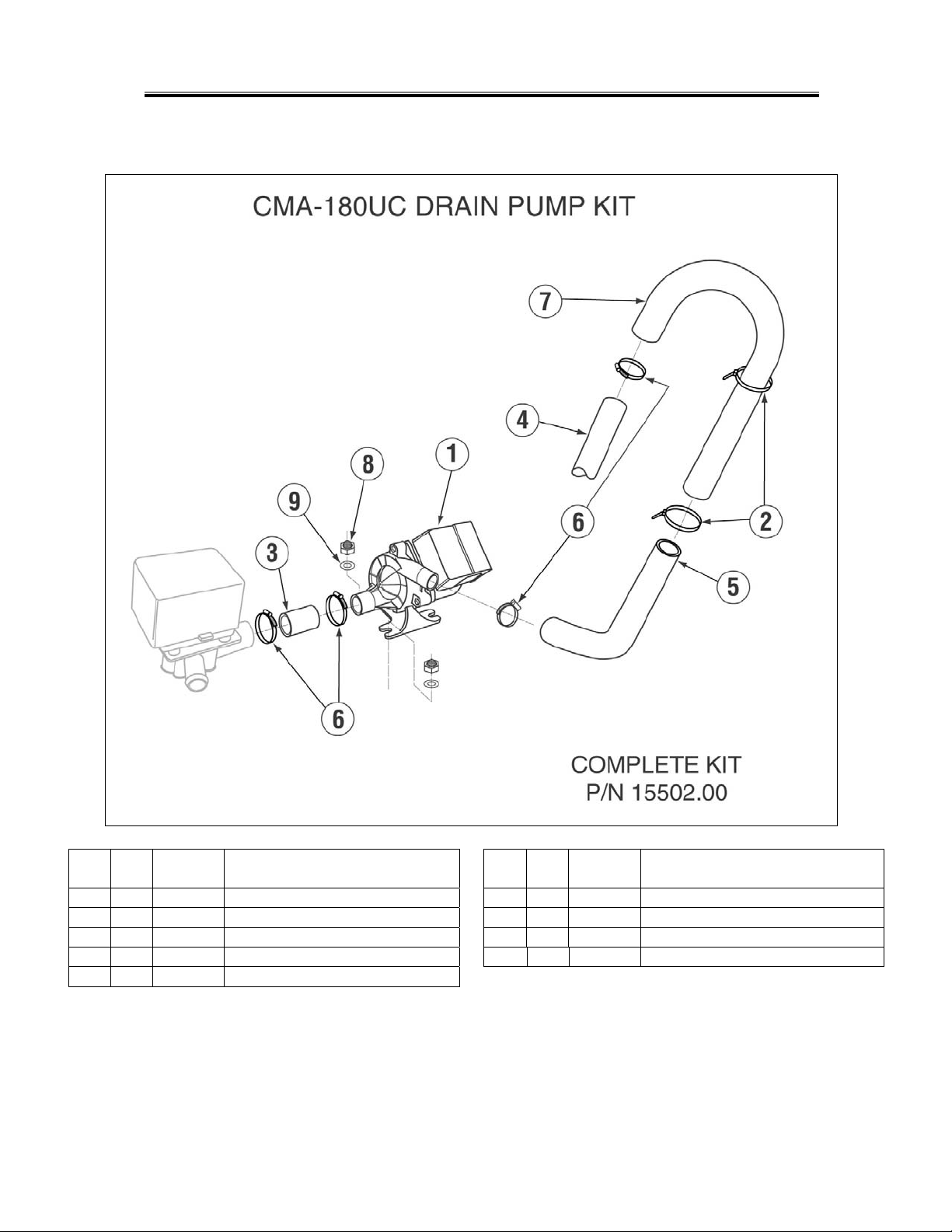
1.2. Optional Drain Pump Kit
Parts Manual
ITEM
NO.
NO.
REQ’D
1 1 15503.00 Drain Motor Ultra Jet for CMA-180UC 6 4 03101.00 Hose Clamp 1”
2 2 00432.50 Twist Tie 7 1 15603.00 Drain Line Gooseneck
3 1 15601.10 Black Drain Hose 1" ID X 3 1/2" 8 2 03801.10 10-32 SS Nut
4 1 15601.50 Drain Hose 1" ID, 6 ft 9 2 04806.00 #10 Brass Washer
5 1 15601.60 Robber Hose 90 Deg.
P/N DESCRIPTION
ITEM
NO.
NO.
REQ’D
P/N DESCRIPTION
MODEL CMA-180UC PARTS MANUAL Rev. 1.14 Page 4
Parts Manual
V
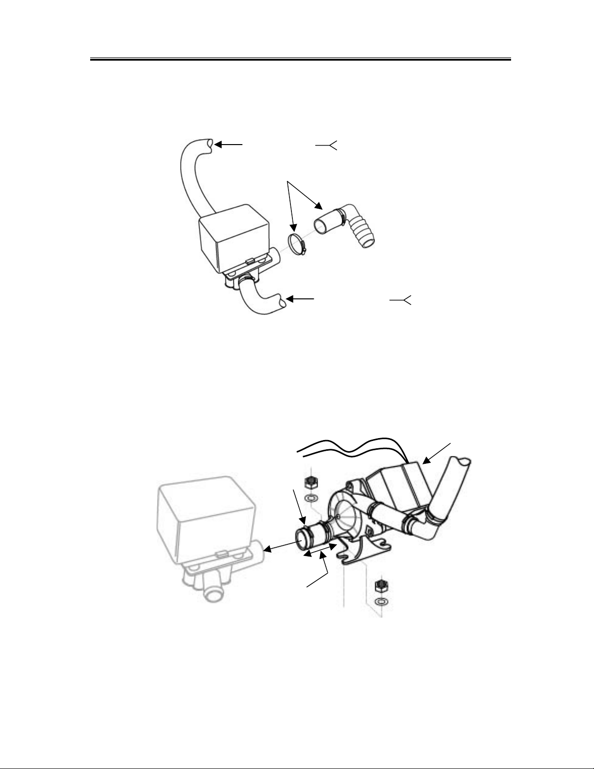
1.3. Optional Drain Pump—INSTALLATION INSTRUCTIONS
1. Start by removing the existing drain hose from the Drain Valve as shown in Figure 1.
From Scrap Tray
Remove
Figure 1
From Wash Tank
2. Locate the white and purple wires that are safe-ended and tie-wrapped at the top of the Drain
Pump compartment. Bring these wires out so they can be connected after mounting the Drain
Pump.
3. Connect the 3-inch long pump inlet drain hose to the Drain Valve and mount the Drain Pump
using the nuts and washers provided with the kit as shown in
White wire
Purple wire
Tighten this
hose clamp
over Drain
alve.
3-inch pump
inlet drain
hose.
Figure 2.
Remove this cover to
make wire connections.
Drain hose must elevate
12 to 16 inches before
dropping to drain.
Figure 2
4.
Remove the terminal cover and connect the white and purple wires to the two white wires
from the pump. Replace the cover.
MODEL CMA-180UC PARTS MANUAL Rev. 1.14 Page 5

Parts Manual
5.
Secure the drain gooseneck to the wash riser pipe with
the hose clamp provided as shown in
6.
Route the drain hose to the drain and provide a 1-inch air gap at the drain.
Figure 3.
Secure with
hose clamp
Figure 3
MODEL CMA-180UC PARTS MANUAL Rev. 1.14 Page 6

1.4. Mechanical Drawings
1.4.1. Cabinet Assembly
Parts Manual
ITEM
NO.
NO.
REQ’D
1 1 14502.82 Side Panel L.H. for CMA-180UC 14 8 00941.00 10-32 x 5/8 Panhead Screw
2 1 14502.84 Side Panel R.H. for CMA-180UC 15 4 03801.00 10-32 Lock Nut
3 1 14503.50 SS Top for CMA-180UC 16 4 00940.51 #10 Internal Lock Star Washer
4 1 14510.00 Scrap Basket for CMA-180UC 17 1 01513.00 Detergent Injection Hole Plug
5 1 14511.00 Tray Track R.H. for CMA-180UC 18 1 00752.00 Detergent Injection Hole Plug Gasket
6 1 14512.00 Tray Track L.H. for CMA-180UC 19 1 00912.00 1/4”-20 Nylon Lock Nut
7 1 14515.00 Lower Front Panel for CMA-180UC 20 1 03705.84 Control Box 2ft Gasket for CMA-180UC
8 1 14560.00 Scrap Tray Drawer for CMA-180UC 21 1 14558.00 Body Magnet Holder for CMA-180UC
9 1 14501.00 SS Body for CMA-180UC 22 2 00557.80 Magnet for CMA-180UC
10 4 01310.60 Leg Adjusters for CMA-180UC 23 2 00927.00 8-32 Lock Nut
11 1 14506.50 Door Gasket for CMA-180UC 24 2 04806.00 #10 Brass Flat Washer
12 1 14506.45 Gasket Bracket for CMA-180UC 25 1 00214.30 1/4" Compression x 3/8” MIP Fitting
13 6 00940.50 10-32 x 3/8 Trusshead Screw
P/N DESCRIPTION
MODEL CMA-180UC PARTS MANUAL Rev. 1.14 Page 7
ITEM
NO.
NO.
REQ’D
DESCRIPTION
P/N

1.4.2. Door Assembly
Parts Manual
ITEM
NO.
NO.
REQ’D
1 1 14506.00 Door for CMA-180UC 10 1 14558.61 Door Magnet Holder for CMA-180UC
2 2 04517.60 Door Support Rod Block 11 2 00965.00 6-32 Lock Nut
3 1 14570.00 Door Hinge R.H. for CMA-180UC 12 2 00605.20 Door Rod Spacer
4 1 14570.50 Door Hinge L.H. for CMA-180UC 13 2 04517.15 Door Stop (Parallel)
5 2 04919.00 Door Rod Screw Pin for CMA-180UC 14 10 00912.00 1/4”-20 Nylon Lock Nut
6 1 04918.60 Door Support Rod Right 15 14 00924.00 1/4” SS Washer
7 1 04919.50 Door Support Rod Left 16 4 00914.10 1/4”-20 x 5/8” Hexhead Bolt
8 2 00557.80 Door Magnet 17 2 14518.00 Splash Guard
9 2 00970.60 6-32 x 1/2” Flathead Screw
P/N DESCRIPTION
MODEL CMA-180UC PARTS MANUAL Rev. 1.14 Page 8
ITEM
NO.
NO.
REQ’D
DESCRIPTION
P/N

1.4.3. Electrical Tray
Parts Manual
ITEM
NO.
NO.
REQ’D
1 1 14504.00 Electrical Tray for CMA-180UC 8 12 00927.00 8-32 Nylon Lock Nut
2 1 14408.80 Timer Assy 4 Cam 2 Min. CMA-180UC 9 1 13426.60 Ground Block
3 1 15504.00 Motor Contactor, 2-Pole 20 Amp 10 2 00965.00 6-32 Lock Nut
4 1 15504.50 Heater Contactor, 2-Pole 35 Amp 11 1 00401.85 3/4” Conduit Connector, Straight
5 1 15520.50 Power Block, 3-Position 12 9 00400.85 3/4” Conduit, Sealtite
6 2 00438.00 Snap Bushing, Universal 13 1 13304.61 HT Plumbing Bracket
7 2 01001.00 6-32 x 1” Panhead Scre w
P/N DESCRIPTION
MODEL CMA-180UC PARTS MANUAL Rev. 1.14 Page 9
ITEM
NO.
NO.
REQ’D
DESCRIPTION
P/N

Parts Manual
1.4.4. Control Panel
ITEM
NO.
NO.
REQ’D
1 1 15520.00 Power Block 12-Position 11 2 01001.00 6-32 x 1” Panhead Screw
2 2 00631.00 Ice Cube Relay 120 V 12 2 00965.00 6-32 SS Nylon Lock Nut
3* 2 03203.00 Dual Temperature Display Kit 13 5 00927.00 8-32 Nylon Lock Nut
4 1 03202.60 Thermometer Transformer 14 6 00911.00 8-32 x 1/2” Panhead Screw
5 1 14503.00 Control Drawer for CMA-180UC 15 1 00557.55 Reed Switch
6 1 15523.00 Rocker Switch Start Momentary 16 4 00917.00 8-32 PM Nut
7 1 15523.50 Rocker Switch Drain/Fill DPDT/Mom. 17 2 03705.82 Sponge Strip
8 1 15524.00 Rocker Switch Power Maintained 18 2 03202.66 Thermocouple
9 1 13426.50 Ground Block 19 2 00971.10 4-40 Nylon Lock Nut
10 1 00438.00 Snap Bushing, Universal *Kit includes 2 of #03202.66
P/N DESCRIPTION
ITEM
NO.
NO.
REQ’D
DESCRIPTION
P/N
MODEL CMA-180UC PARTS MANUAL Rev. 1.14 Page 10

Parts Manual
1.4.5. Plumbing System Assembly
ITEM
NO.
NO.
REQ’D
1 1 15602.20 SS Braided Hose 12" 1/2IP x 3/8C 14 1 00739.50 Vacuum Breaker Cap, SS
2 1 00798.00 SS Braided Hose 20" 15 1 03624.25 Vacuum Breaker Bonnet, Brass
3 2 03604.00 SS Water Solenoid Valve 1/2" 16 1 03623.00 1/2” Vac. Breaker Repair Kit – Watts
4 4 00760.00 5/8” Compression x 1/2” MIP Adapter 17 2 03614.00 Nipple, Brass 1/2” Close
5 2 00725.60 1/2” Plumbing Strap 18 1 03232.00 1/8” Male Plug
6 1 05007.66 Solenoid and Valve Line 19 1 13669.45 SS Mixing Chamber CMA-180UC
7 2 00915.00 1/4”-20 SS Nut 20 1 00798.00 1/2” SS Braided Hose
8 1 00745.00 1/2” 90° Elbow M x F (RM) 21 2 00915.00 1/4”-20 SS Nut
9 1 41062.00 1/2" Strainer Ball Valves 22 2 00724.00 1/2” Compression x 1/2” MIP Adapter
10 1 00214.60 1/4” Compression x 1/2” MIP FTG 23 1 13304.53 Long Support Bracket
11 2 00743.10 1/2" T,FxFxF 24 1 00798.40 SS Braided Hose 12”
12 1 05007.60 Vacuum Breaker Line 25 1 13605.45 Pressure Gauge for CMA-180UC
13 1 03624.00 1/2” Vacuum Breaker – Watts 26 1 40137.00 1/4 Street Elbow 90 Deg
P/N DESCRIPTION
MODEL CMA-180UC PARTS MANUAL Rev. 1.14 Page 11
ITEM
NO.
NO.
REQ’D
DESCRIPTION
P/N

1.4.6. Drain System Assembly
Parts Manual
ITEM
NO.
NO.
REQ’D
1 1 04103.00 L1X/L1-C Drain Valve 120V 4 1 04106.00 1” 90° Barb x Barb Elbow
2 6 03101.00 Hose Clamp #16-1” 5 1 15601.10 Black Drain Hose 1" ID X 3 1/2"
3 2 15601.60 Hose 1” ID 7” Pump to Manifold
P/N DESCRIPTION
ITEM
NO.
NO.
REQ’D
DESCRIPTION
P/N
MODEL CMA-180UC PARTS MANUAL Rev. 1.14 Page 12

1.4.7. Wash System
Parts Manual
ITEM
NO.
NO.
REQ’D
1 2 00304.45 Wash Arm 3 2 04305.17 Red Silicon Gasket 1/16” Thick
2 4 00308.20 Wash Arm End Plug
P/N DESCRIPTION
ITEM
NO.
NO.
REQ’D
DESCRIPTION
P/N
MODEL CMA-180UC PARTS MANUAL Rev. 1.14 Page 13

Parts Manual
1.4.8. Rinse System
ITEM
NO.
NO.
REQ’D
1 2 00304.65 Rinse Arm CMA-180UC 3 2 04305.17 Red Silicon Gasket 1/16” Thick
2 8 13304.55 SS Final Rinse Spray Jet – HT 4 4 00308.17 Rinse Arm End Cap
P/N DESCRIPTION
ITEM
NO.
NO.
REQ’D
P/N DESCRIPTION
MODEL CMA-180UC PARTS MANUAL Rev. 1.14 Page 14

1.4.9. Pump System Assembly
Parts Manual
ITEM
NO.
NO.
REQ’D
1 4 00908.00 5/16”-18 SS Hexhead Bolt 10 1 04206.00 Pump Cover
2 4 00926.00 5/16” SS Washer 11 1 00208.00 Slip Joint Nut Gasket
3 4 00913.00 5/16”-18 Hex Nut 12 1 04204.00 L-1X Compression Nut 2.5”
4 1 00208.20 Slip Joint Ring 13 1 00213.50 Pump Fitting
5 1 00201.66 Water Pump Motor for CMA-180UC 14 2 00301.00 1” Hose Clamp #16
6 8 00921.00 3/8”-16 x 3/4” Hex Bolt 15 1 03108.60 1” Reinforced Hose
7 1 03224.00 Pump Base (Mount) 16 1 03226.00 Pump “O” Ring Gasket
8 1 00206.00 Pump Seal Kit 17 2 00238.00 3/8” Male Plug
9 1 03222.05 Impeller L-1M
P/N DESCRIPTION
ITEM
NO.
NO.
REQ’D
P/N DESCRIPTION
MODEL CMA-180UC PARTS MANUAL Rev. 1.14 Page 15

Parts Manual
1.4.10. Heater Assembly
ITEM
NO.
NO.
REQ’D
1 1 15517.00 Heater 6kW for CMA-180UC 6 4 00926.00 5/16” SS Washer
2 1 13417.89 Heater Thermostat 7 1 40116.00 1/4” Compression x 1/4” MIP FTG
3 1 17523.60 High Limit Switch 200°F 8 2
4 1 15517.10 Heater Gasket 9 2
5 4 13805.00 5/16”-18 Nylon Insert Lock Nut
P/N DESCRIPTION
ITEM
NO.
NO.
REQ’D
P/N DESCRIPTION
00965.00 6-32 Lock Nut
17524.00 High Limit Switch Spacer
MODEL CMA-180UC PARTS MANUAL Rev. 1.14 Page 16
 Loading...