

Page 1
CMA DISHMACHINES
GARDEN GROVE, CALIFORNIA 92841
FAX 714-895-2141
MODELS
Rev 1.03B
AH/B/C/Scullery/Pizza/Bowl
PARTS MANUAL
12700 KNOTT AVENUE
800- 854- 6417
Page 2

TABLE OF CONTENTS
MODEL AH/B/C/S.
1. PARTS MAN UAL .......................................................................................... 4
1.1. INITIAL PARTS KIT (P/N 01100.20) ..................................................................................................... 4
1.2. EXPLODED VIEW DRAWINGS ............................................................................................................... 5
1.2.1. Cabinet Assembly for Model AH ................................................................................................. 5
1.2.2. Cabinet Assembly for Model B ................................................................................................... 6
1.2.3. Cabinet Assembly for Model B Energy Saver ............................................................................. 7
1.2.4. Cabinet Assembly for Model CB Right Door Only ..................................................................... 8
1.2.5. Cabinet Assembly for Model CB Left Door Only........................................................................ 9
1.2.6. Cabinet Assembly For Model C .............................................................................................. 10
1.2.7. Control Box Assembly for Model AH, B and C ......................................................................... 11
1.2.8. Door Actuator Assembly ........................................................................................................... 12
1.2.9. Door Actuator Assembly for Model C....................................................................................... 13
1.2.10. Pump Assembly AH and C ........................................................................................................ 14
1.2.11. Pump Assembly For Model B ................................................................................................... 15
1.2.12. Plumbing System Assembly for Model AH and C ..................................................................... 16
1.2.13. Plumbing System Assembly for Model B................................................................................... 17
1.2.14. Spray System Assembly for Model AH ...................................................................................... 18
1.2.15. Spray System Assembly for Models B/CB Left .......................................................................... 19
1.2.16. Spray System Assembly for Model B Energy Saver .................................................................. 20
1.2.17. Spray System Assembly for Model C ........................................................................................ 21
1.2.18. Drain System Assembly for Model AH and C ........................................................................... 22
1.2.19. Drain System Assembly for Model B......................................................................................... 23
1.2.20. Peristaltic Pump Assembly ....................................................................................................... 24
1.2.21. Unique Parts For Scullery AH .................................................................................................. 25
1.2.22. Unique Parts For Scullery B..................................................................................................... 26
1.2.23. Unique Parts For Scullery C .................................................................................................... 27
1.2.24. Unique Parts For Pizza Machines ............................................................................................ 28
1.3. OPTIONAL SOLID BOWL .................................................................................................................... 29
1.4. OPTIONAL SANI ALARM .................................................................................................................... 30
1.5. TEMP-SURE HEATER. ........................................................................................................................ 31
Page 3

1. Parts Manual
1.1. Initial Parts Kit (P/N 01100.20)
P/N DESCRIPTION Qty
00100.00 Drain Ball Solenoid 120V 1
00120.02 Thermometer (Bi Metal) 1
00121.30 Drain Ball 1
00200.10 Pump Assy 110/220V 60Hz (Open) 1
00206.30 Pump Seal Kit 1
00304.03 Spray Arm B L1-C & L-1X 1
00304.06 Spray Arm A & C 1
00308.50 Spray Arm End Plug SS 1
00341.00 Spray Arm Bearing (Cleanable) 1
00363.00 Spray Base Lock Pin 1
00404.82 Motor Contactor 120 VAC 1
00411.00 Micro Switch 1
00415.00 Peristaltic Pump Assy 120V/60Hz 1
00418.00 Peristaltic Pump Cover 1
00421.40 Start/Fill switch 1
00433.00 Master Switch (30 Amp) 1
00500.00 Timer Motor 90 Sec 110V/60Hz 1
00562.00 Roller Door Switch 1
00631.00 Ice Cube Relay 120V 1
00706.00 3/4 Water Solenoid Repair Kit JE 1
00715.00 1/2 Ball Check Valve 1
00735.00 3/4 Vac Breaker Rep Kit Watts 1
00738.10 Solenoid Coil JE 120V (3/4 &1/2) 1
02257.00 Squeeze Tube 8" 1
Parts Manual
MODEL AH, B & C PARTS MANUAL Rev. 1.03B Page
4
Page 4
Parts Manual
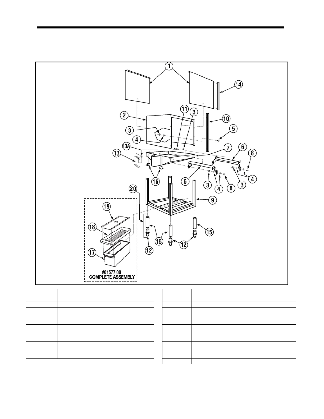
1 2 01506.30
Door
11 3 00725.50
1/2" Plumbing Strap
3
33
00912.00
1/4-20 Lock Nut
13 1 01558.20
Chemical Tube Support Bracket
4
50
00926.00
SS Washer 1/4"
13A 4 00427.00
Line Bracket Snap Bushing
6 1 01505.02
Tray Track (Set)
15 4 01572.10
SS Leg (A, AH, C, B)
7 1 01531.02
Pan
16 2 01571.00
Drain Baffle
8
17
00906.00
1/4-20 x 1/2" Hex Head Bolt
17 1 01577.10
Scrap Trap Body Molded
10 4 01554.30
EZ Glide Door Guide SS
19 1 01577.30
S/S Scrap Trap Lid Molded
20
--
01145.00
Leg Assembly, 10” w/Bullet Foot
1.2. Exploded View Drawings
1.2.1. Cabinet Assembly for Model AH
ITEM
NO.
NO.
REQ’D
2 1 01530.02 Wrapper 12 4 01310.00 Bullet Foot
5 16 00905.00 1/4-20 x 1/2" Truss Head Bolt 14 4 00636.10 EZ Glide Plastic Guide
9 1 01532.52 Frame Stand 18 1 01577.21 S/S Scrap Trap Drawer
MODEL AH, B & C PARTS MANUAL Rev. 1.03B Page
P/N DESCRIPTION
ITEM
NO.
NO.
REQ’D
P/N DESCRIPTION
5
Page 5

Parts Manual
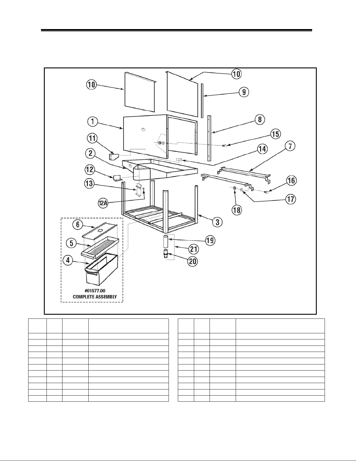
1 1 01530.03
Wrapper (TM-B)
12 2 01571.00
Drain Baffle
2 1 01501.03
Pan Double (B)
12A 4 00427.00
Snap Bushing 375-4
4 1 01577.10
Scrap Trap Body Molded
14 3 00725.50
1/2" Plumbing Strap
5 1 01577.21
SS Scrap Trap Drawer
15
16
00905.00
Trusshead Bolt 1/4"-20 x 1/2"
6 1 01577.30
SS Scrap Trap Lid
16
22
00906.00
Hex Head Bolt 1/4"-20 x 1/2"
8 4 01554.30
EZ Glide Door Guide SS 21 1/8”
18
38
00912.00
SS Nylon Lock Nut, 1/4"
9 4 00636.10
EZ Glide Door Guide (Plastic)
19 4 01572.10
SS Leg (A, AH, C, B)
11 2 01505.13
Support Bracket for B Tray Track
21
---
01145.00
Leg Assembly, 10” w/Bullet Foot
1.2.2. Cabinet Assembly for Model B
ITEM
NO.
NO.
REQ’D
3 1 01532.53 Stand TM-B (w/o Legs) 13 1 01558.20 Chemical Tube Support Bracket
7 1 01505.03 Tray Track B (Set of 2) 17 72 00924.00 SS Washer, 1/4"
10 2 01506.30 SS Door (A, B, C, M, CMA-44) 20 4 01310.00 Bullet Foot
MODEL AH, B & C PARTS MANUAL Rev. 1.03B Page
P/N DESCRIPTION
ITEM
NO.
NO.
REQ’D
P/N DESCRIPTION
6
Page 6
Parts Manual
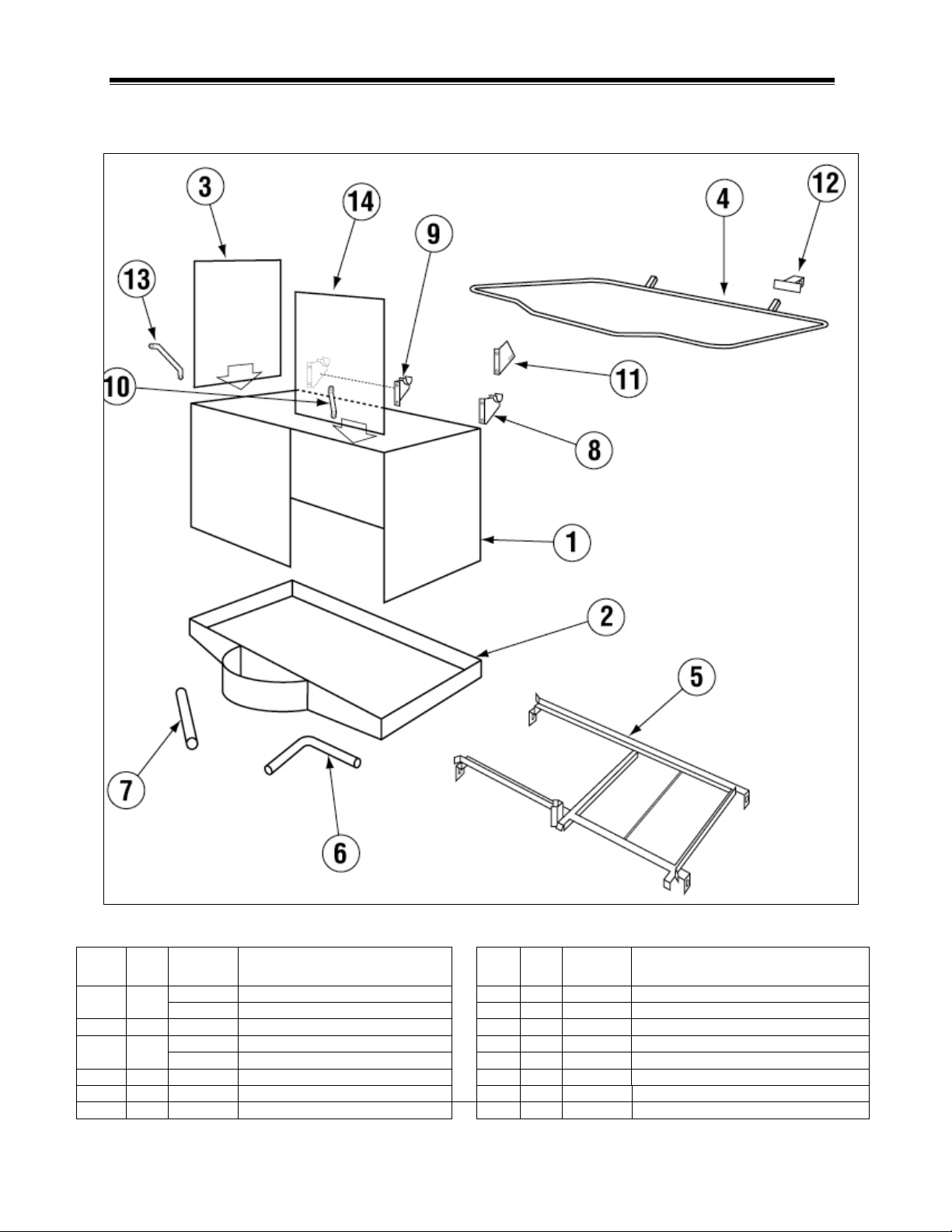
2 1 01501.43
ES-B Pan
12A 4 00427.00
Snap Bushing 375-4
3 1 01532.53
Stand TM-B (w/o Legs)
13 1 01558.20
Chemical Tube Support Bracket
5 1 01577.21
S/S Scrap Trap Drawer
15
16
00905.00
Trusshead Bolt 1/4"-20 x 1/2"
6 1 01577.30
S/S Scrap Trap Lid
16
22
00906.00
Hex Head Bolt 1/4"-20 x 1/2"
7 1 01505.03
Tray Track B (Set of 2)
17
72
00924.00
SS Washer, 1/4"
9 4 00636.15
EZ Glide Door Guide 25 7/8"
19 4 01572.10
SS Leg (A, AH, C, B)
10 2 01506.10
Door (Pizza) Dimple And Stamped
20 4 01310.00
Bullet Foot
1.2.3. Cabinet Assembly for Model B Energy Saver
ITEM
NO.
NO.
REQ’D
1 1 01530.53 ES B Wrapper -Tall 12 2 01571.00 Drain Baffle
4 1 01577.10 Scrap Trap Body Molded 14 3 00725.50 1/2" Plumbing Strap
8 4 17554.00 CMA-180/Pizza Door Guide 24 18 38 00912.00 SS Nylon Lock Nut, 1/4"
11 2 01505.13 Support Bracket for B Tray Track 21 --- 01145.00 Leg Assembly, 10” w/Bullet Foot
MODEL AH, B & C PARTS MANUAL Rev. 1.03B Page
P/N DESCRIPTION
ITEM
NO.
NO.
REQ’D
P/N DESCRIPTION
7
Page 7
Parts Manual
01530.24
Wrapper CB (For RD)
7 1 00246.14
Motor suction Tube CB (For RD)
2 1 01501.24
Pan CB (For RD)
9 1 01555.50
LH Door Handle Support Bracket
01506.25
Side Door CB (For RD)
10 1 01553.24
Door Handle Link CB
01506.65
Side Door For (CB-T) Right Door
11 1 00563.40
Door Switch Bracket (8-08)
5 1 01505.24
Tray track CB(RD)
13 1 01553.30
Door Handle Link(CB)Banana Style 10"
6 1 00246.24
Motor suction Tube CB (For RD)
14 1 01506.10
Door (Pizza) with Dimple And Stamped
1.2.4. Cabinet Assembly for Model CB Right Door Only
ITEM
NO.
NO.
REQ’D
1 1
3 1
4 1 00613.25 Door Handle CB (Right) 12 1 00563.42 Door Switch Actuator (8-08)
MODEL AH, B & C PARTS MANUAL Rev. 1.03B Page
P/N DESCRIPTION
01530.84 Wrapper CB-Tall (For Right Door) 8 1 01556.50 RH Door Handle Support Bracket
ITEM
NO.
NO.
REQ’D
P/N DESCRIPTION
8
Page 8

Parts Manual
01530.25
Wrapper CB (For LD)
8 1 00246.15
Motor suction Tube CB (For LD)
2 1 01501.25
Pan CB (For LD)
10 1 01556.50
RH Door Handle Support Bracket
01506.24
Side Door CB (For LD)
11 1 01553.24
Door Handle Link CB
4 1 00613.24
Door Handle CB (Left)
13 1 00563.42
Door Switch Actuator (8-08)
5 1 01505.25
Tray Track CB (LD)
14 1 00563.40
Door Switch Bracket (8-08)
6 1 00111.25
Drain Sump Casting CB (LD)
15 1 01506.10
Door (Pizza) with Dimple And Stamped
1.2.5. Cabinet Assembly for Model CB Left Door Only
ITEM
NO.
NO.
REQ’D
1 1
3 1
7 1 00246.25 Motor suction Tube CB (For LD)
P/N DESCRIPTION
01530.85 Wrapper CB-Tall (For Left Door) 9 1 01555.50 LH Door Handle Support Bracket
01506.64 Side Door (CBT) Left Door 12 1 01553.30 Door Handle Link (CB)Banana Style 10"
MODEL AH, B & C PARTS MANUAL Rev. 1.03B Page
ITEM
NO.
NO.
REQ’D
P/N DESCRIPTION
9
Page 9

Parts Manual
2 1 01501.04
Fram e Pan (C)
15 1 00101.10
Solenoid Bracket CRH
3 1 01532.54
Frame Stand
16
16
00905.00
Trusshead Bolt 1/4"-20 x 1/2"
5 2 01506.30
Door A, B, C, M, CMA-44
18
34
00912.00
Nylon Lock Nut, 1/4"-20
6 4 01554.30
Door Guide SS 21 1/8”
19
12
00914.10
Hexhead Bolt ¼-20 x 5/ 8 "
7 4 00636.10
EZ Glide Door Guide (Plastic)
20
12
0906.00
Hexhead Bolt ¼-20 x ½ "
9 1 01577.10
Scrap Trap Body Molded
22 1 01570.24
Pan Support Bracket C
10 1 01577.21
S/S Scrap Trap Drawer
23 1 01577.50
Molded Scrap Trap Mount Bracket
12 4 01310.00
Bullet Feet
25 1 00912.00
¼ x20 Nylon Lock Nut
13 2 01571.00
Drain Baffle
26 1 00911.00
8-32x1/2 ‘’Pan Head Screw
28 1 01145.00
^Leg Assy 10" w\Adjustable Socket
1.2.6. Cabinet Assembly For Model C
1 1 01500.04
4 4 01572.10 Stand Legs (A, AH, C, B)* 17 1 00101.20 Solenoid Bracket CLH
8 1 01505.04 Tray Track Corner 21 68 00924.00 1/4’’ SS Washer
11 1 01577.30 S/S Scrap Trap Lid Molded 24 1 00924.00 1/4" SS Washer
14 1 01558.20 Chemical Tube Support Bracket 27 1 01577.00 Scrap Trap Assy (Poly Pro)
MODEL AH, B & C PARTS MANUAL Rev. 1.03B Page
Wrapper Includes Brackets #15,17
14A 4 00427.00 Line Bracket Snap Bushing
10
Page 10

Parts Manual
1 1 01503.14
Control Box Body AH-B-C
22 3 00918.00
8-32 X 1 ½” Fillister Bolt
3 1 00407.80
Timer 90 Sec 8 Cam 120V
24 1 00464.07
3/8” SS Tubing (For Solenoid Wire
4
1(2)
00404.82
Motor Contactor 120V AH/C (B)
25 1 00436.00
3/8” 90Deg Elbow Comp X Mip
5 1 00433.10
Master Switch (20Amp)
26 1 00712.00
3/8” jamb Nut (Plated)
7 1 00454.10
3 Pole Socket Terminal Block
28 1 03408.50
Counter (Panel Mount) 120V
8 1 13825.00
8-32 X 1” Pan Head Screw
29 3 03470.00
Primer Switch (Momentary)
10 1 00449.00
Lock and Key
31 1 00562.60
Roller Switch Connector
11 8 00411.00
Microswitch
32 1 00421.40
Start/Fill Switch (With light)
13 4 00911.50
8-32 X 3/8” Pan Head Screw
34 4 00914.00
¼ “ –20 X ¾” Hex Head Bolt
14
AR
00400.00
Conduit 3/8” Sealtite
35 4 00922.00
¼” Lock Star Washer
16 4 00402.00
St. 90Deg 3/8” Connector
37 1 00535.00
Control Box Lid Handle
17 4 00438.00
Snap Bushing 875-11
38 1 01514.00
Timer Support Bar
18 3 00416.00
Peristaltic Pump Motor 120V
39 4 00470.10
Toggle Switch Rubber Boot
20 3 00419.00
Peristaltic Pump Rotor
41 1 00927.00
8-32 Nylon Lock Nut
21 6 00919.00
8-32 X 1 ½” Panhead Bolt
42 3 00418.00
Peristaltic Pump Cover
1.2.7. Control Box Assembly for Model AH, B and C
ITEM
NO.
NO.
REQ’D
2 1 01504.14 Control Box Lid AH-B-C 23 12 00911.00 8-32 X ½” Panhead screw
6 1 00631.00 Ice Cube relay 120V 27 1 00712.30 3/8” jamb Nut (standard)
9 1 00450.00 Key Only 30 1 00475.00 Delimer Switch (DPDT 15Amp)
12 1 00500.00 Timer Motor 120V (For 90Sec Timer) 33 3FT 00547.00 Switch Cord
15 2 00401.00 St. Straight 3/8” Connector 36 4 00912.00 ¼”-20 Nylon Lock Nut
19 3 00417.10 Peristaltic Pump Bloc k 40 1 00562.00 Roller Switch
P/N DESCRIPTION
ITEM
NO.
NO.
REQ’D
P/N DESCRIPTION
MODEL AH, B & C PARTS MANUAL Rev. 1.03B Page
11
Page 11

Parts Manual
00613.33
Door Handle, 1” (Model B)
13 8 00912.00
1/4-20 Nylon Locknut
2 1 01556.50
Door Handle Support, 1” (Right)
14 4 00610.00
Door Handle Spacer, Small
3 2 00603.07
Door Spring Extension Rod
15 4 00611.00
Door Handle Spacer, Large
5 2 01506.30
Door (Cut Away)
17 1 01555.50
Door Handle Support, 1” (Left)
6 2 01553.00
Door Handle Link
18 2 00903.00
1/4-20 x 1-3/4” Hex Head Bolt
8 2 00913.00
5/16-18 Nut
20 2 01552.00
Door Stop
9 2 00926.00
5/16” SS Washer
21 1 00563.40
Door Switch Bracket (8-08)
11 4 00906.00
1/4-20 x 1/2" Hex Head Screw
1.2.8. Door Actuator Assembly
ITEM
NO.
NO.
REQ’D
1 1 00613.32 Door Handle, 1” (Model AH) 12 6 00924.00 1/4" SS Washer
4 2 00602.00 Door Spring (# 602.20 B & S models) 16 2 00910.00 1/4-20 x 1-1/2” Hex Bolt
7 2 00606.50 Turn Buckle 19 2 00607.04 Door Handle Cap, 1”
10 2 00900.00 Cotter Pin 22 1 00563.42 Door Switch Actuator (8-08)
MODEL AH, B & C PARTS MANUAL Rev. 1.03B Page
P/N DESCRIPTION
ITEM
NO.
NO.
REQ’D
P/N DESCRIPTION
12
Page 12

Parts Manual
2 1 00619.34
Door Handle Mounting Plate, Long
12 6 00924.00
1/4" SS Washer
2A 1 00619.44
Door Handle Mounting Plate, Short
13 4 00912.00
1/4-20 Nylon Lock Nut
4 2 00602.00
Door Spring (# 602.20 S model)
15 4 00611.00
Door Spacer, Large
5 2 01506.30
Door (Cut Away)
16 2 00903.00
1/4-20 x 1-3/4” Hex Head Bolt
6 2 01553.00
Door Handle Link
17 8 00926.00
5/16” SS Washer
8 9 00913.00
5/16-18 Nut
19 2 00607.04
Door Handle Cap
9 9 00926.00
5/16 SS Washer
20 8 00920.00
5/16-18 x 3/4" Hex Head Bolt
1.2.9. Door Actuator Assembly for Model C
ITEM
NO.
NO.
REQ’D
1 1 00613.04 Door Handle 11 2 01552.00 Door Stop
3 1 00603.04 Extension Rod 14 4 00610.00 Door Handle Spacer, Small
7 1 00606.50 Turn Buckle 18 2 00910.00 1/4-20 x 1-1/2” Hex Head Screw
10 1 13805.00 5/16-18 Nylon Lock Nut 21 1 00563.20 Limit Switch Door Brack et
MODEL AH, B & C PARTS MANUAL Rev. 1.03B Page
P/N DESCRIPTION
ITEM
NO.
NO.
REQ’D
P/N DESCRIPTION
13
Page 13

Parts Manual
1 1 00201.00
Pump Motor, 1 HP
12 1 00246.01
Motor Suction Tube (A/AH)
2 2 00975.00
3/8”-16 x 1 ½” SS Stud
12A 1 00246.04
Motor Suction Tube (C)
4 2 00207.00
1 ½” x 1 ¼” Slip Joint Nut
14 1 00906.00
1/4”-20 x ½” Hex Head Bolt
5 3 00208.40
Slip Joint Nut Gasket
15 1 00924.00
¼” SS Washer
7 1 03224.00
Pump Base Small
17* 1 00200.10
Pump Assy.
8 1 03226.00
Pump O-Ring
18 1 00214.50
1/2 Comp x 3/8” M.I.P. F.T.G.
9 1 03222.10
Open Impeller
19 6 00921.00
3/8”-16 x ¾” SS Head Bolt
11
1
04204.00
Compression Nut (2.5”)
21 1 00238.00
3/8 Mail Plug
1.2.10. Pump Assembly AH and C
ITEM
NO.
NO.
REQ’D
3 1 00206.30 Pump Seal Kit 13 1 13916.20 Motor Support Bracket
6 1 00768.20 Pump Inlet Elbow SS Casting 16 1 00912.00 1/4"-20 Nylon Lock Nut
10 1 04206.00 Pump Cover, Small 20 3 00208.21 Slip Joint Nut Friction Ring
*P/N 00200.10 includes items 1, 3, 7, 8, and 9 already assembled.
P/N DESCRIPTION
ITEM
NO.
NO.
REQ’D
P/N DESCRIPTION
MODEL AH, B & C PARTS MANUAL Rev. 1.03B Page
14
Page 14

Parts Manual
1 1 00201.00
Pump Motor, 1 HP
11 1 04204.00
Compression Nut (2.5”)
2 2 00975.00
3/8”-16 x 1 ½” SS Stud
12 1 00246.23
Motor Suction Tube
3 1 00206.30
Pump Seal Kit
13 1 13916.20
Motor Support Bracket
5 3 00208.40
Slip Joint Nut Gasket
15 3 00924.00
¼” SS Washer
6 1 00768.20
Pump Inlet Elbow SS Casting
16 3 00912.00
1/4"-20 Nylon Lock Nut
8 1 03226.00
Pump O-Ring
18 1 00214.50
1/2 Comp x 3/8” M.I.P. F.T.G.
9 1 03222.10
Open Impeller
19 6 00921.00
3/8”-16 x ¾” SS Head Bolt
10 1 04206.00
Pump Cover, Small
20 3 00208.21
Slip Joint Nut Friction Ring
21 1 00238.00
3/8” Mail Plug
*P/N 00200.10 includes items 1, 3, 7, 8, and 9 already assembled.
1.2.11. Pump Assembly For Model B
ITEM
NO.
NO.
REQ’D
4 2 00207.00 1 ½” x 1 ¼” Slip Joint Nut 14 3 00906.00 1/4”-20 x ½” Hex Head Bolt
7 1 03224.00 Pump Base Small 17* 1 00200.10 Pump Assy.
P/N DESCRIPTION
ITEM
NO.
NO.
REQ’D
P/N DESCRIPTION
MODEL AH, B & C PARTS MANUAL Rev. 1.03B Page
15
Page 15

Parts Manual
1 1 13029.00
3/4"Strainer Ball Valve*
16* 1 00739.50
Vacuum Breaker Cap SS
2 1 00798.00
SS Braided Hose
17 1 00738.10
Solenoid Coil, J/E
3 1 00715.00
Ball Check Valve
18 1 00705.20
Water Solenoid Valve Bonnet
5 1 00214.50
1/2" Comp x 3/8” MIP Fitting
20 1 00786.00
Water Solenoid Plunger, G Style ¾” x ½”
6 1 00795.00
Flush Tube
21 1 00706.00
Repair Kit (Water Solenoid)
8 1 00770.20
5/8 Compression Ftg. Ring
23 1 00705.00
3/4" Water Solenoid
9 1 00770.00
Water Inlet Elbow Assy
24 1 00781.00
3/4" x 3-½” Nipple, Brass
10 2 00721.00
1/2" Jamb Nut
25 1 14508.50
Plumbing Support Bracket
11 1 00748.00
Sprinkler Head
26 1 00704.00
3/4" Street Elbow
12 2 00701.00
3/4" x 1-½” Nipple
27 1 00912.00
1/4"-20 Nylon Lock Nut
13 2 00704.00
3/4" Street Elbow
27A 1 00926.00
1/4" SS Washer
15 1 00735.60
Vacuum Breaker Bonnet, Brass
1.2.12. Plumbing System Assembly for Model AH and C
ITEM
NO.
NO.
REQ’D
4 1 00760.00 5/8” Comp x 1/2” MIP Fitting 19 1 00710.50 3/4" Vacuum Breaker
7 1 00770.10 5/8 Compression Ftg. Nut 22 1 00706.10 3/4" Solenoid Plunger, Spring Only
14 1 00735.00 Repair Kit (Vacuum Breaker) 28 1 13029.10 ^3/4 Bal l Valve Strainers Only
MODEL AH, B & C PARTS MANUAL Rev. 1.03B Page
P/N DESCRIPTION
ITEM
NO.
NO.
REQ’D
P/N DESCRIPTION
* Comes with 16A screws P/N 421.51
16
Page 16

Parts Manual
1 1 13029.00
3/4"Strainer Ball Valve
16* 1 00739.50
Vacuum Breaker Cap SS
2 1 00798.00
SS Braided Hose
17 1 00738.10
Solenoid Coil, J/E
3 1 00715.00
Ball Check Valve
18 1 00705.20
Water Solenoid Valve Bonnet
4 1 00760.00
5/8” Comp x 1/2” MIP Fitting
19 1 00710.50
3/4" Vacuum Breaker
5 1 00214.50
1/2" Comp x 3/8” MIP Fitting
20 1 00786.00
Water Solenoid Plunger, G Style ¾” x ½”
6 1 00795.00
Flush Tube
21 1 00706.00
Repair Kit (Water Solenoid)
8 1 00770.20
5/8 Compression Ftg. Ring
23 1 00705.00
3/4" Water Solenoid
9 1 00770.00
Water Inlet Elbow Assy
24 1 00781.00
3/4" x 3-½” Nipple, Brass
11 1 00748.00
Sprinkler Head
26 1 00704.00
3/4" Street Elbow
12 2 00701.00
3/4" x 1-½” Nipple
27 1 00912.00
1/4"-20 Nylon Lock Nut
14 1 00735.00
Repair Kit (Vacuum Breaker)
28 1 00743.10
½” Tee FxFxF Brass
15 1 00735.60
Vacuum Breaker Bonnet, Brass
29 1 13029.10
^3/4 Ball Valve Strainers Only
1.2.13. Plumbing System Assembly for Model B
ITEM
NO.
NO.
REQ’D
7 1 00770.10 5/8 Compression Ftg. Nut 22 1 00706.10 3/4" Solenoid Plunger, Spring Only
10 2 00721.00 1/2" Jamb Nut 25 1 14508.50 Plumbing Support Bracket
13 2 00704.00 3/4" Street Elbow 27A 1 00926.00 1/4" SS Washer
MODEL AH, B & C PARTS MANUAL Rev. 1.03B Page
P/N DESCRIPTION
ITEM
NO.
NO.
REQ’D
* Comes with 16A screws P/N 421.51
P/N DESCRIPTION
17
Page 17

Parts Manual
1 1 00361.00
Upper Spray Base, SS*
9
16
00924.00
1/4" SS Washer
2 1 00360.00
Lower Spay Base, SS*
10 2 00302.51
O-Ring Spray Base
4 1 00303.32
Manifold, AH
12 2 00341.00
Spray Arm Bearing
5 4 00363.00
Spray Base Lock Pin**
13 4 00929.00
1/4"-20 x 3/4" Trusshead Bolt
6 4 00308.50
Spray Arm End Plug
14 1 00363.10
Lock Arm Spring
8 8 00912.00
1/4 Nylon Lock Nut
1.2.14. Spray System Assembly for Model AH
ITEM
NO.
NO.
REQ’D
3 2 00304.04 Spray Arm A/C Series 11 4 00914.10 1/4"-20 x 5/8” Hexhead Bolt
7 1 00302.00 Spray Base Gasket 15 2 00966.10 10-32 x 1/4" Hexhead Bolt
MODEL AH, B & C PARTS MANUAL Rev. 1.03B Page
P/N DESCRIPTION
ITEM
NO.
NO.
REQ’D
* Includes item 5, P/N 00363.00
** Includes item 14, P/N 00363.10
P/N DESCRIPTION
18
Page 18

Parts Manual
1 1 00361.40
Upper Spray Base, SS*
9
16
00924.00
1/4" SS Washer
2 1 00360.40
Lower Spay Base, SS*
10 2 00302.51
O-Ring Spray Base
4 1 00303.33
Manifold B
12 4 00341.00
Spray Arm Bearing
5 4 00363.00
Spray Base Lock Pin**
13 4 00929.00
1/4"-20 x 3/4" Truss Head Bolt
6 4 00308.50
Spray Arm End Plug
14 1 00363.10
Lock Arm Spring
7 1 00302.00
Spray Base Gasket
15 2 00966.10
10-32 x 1/4" Hex Head Bolt
8 8 00912.00
1/4 Nylon Lock Nut
1.2.15. Spray System Assembly for Models B/CB Left
ITEM
NO.
NO.
REQ’D
3 4 00304.03 Spray Arm B Series 11 4 00914.10 1/4"-20 x 5/8” Hex Head Bolt
MODEL AH, B & C PARTS MANUAL Rev. 1.03B Page
P/N DESCRIPTION
ITEM
NO.
NO.
REQ’D
* Includes item 5, P/N 00363.00
** Includes item 14, P/N 00363.10
P/N DESCRIPTION
19
Page 19

Parts Manual
1 4 00914.00
1/4-20 X 3/4 Hexhead Bolt
9 1 04306.00
Square Manifold Gasket
2 9 00924.00
1/4 SS Washer
10 1 00905.82
1/4-20 X 3/8 Truss Head Bolt
4 1 00966.10
10-32 X 1/4 Hexhead SS Bolt
12 4 00363.00
Spray Base Lock Pin*
5 4 00342.00
ES Spray Arm Bearing
13 4 00302.51
O-Ring Spray Base
7 4 00308.50
Spray Arm End Plug SS
8 1 00305.44
ES-PB Manifold w/ Upper Spray
1.2.16. Spray System Assembly for Model B Energy Saver
ITEM
NO.
NO.
REQ’D
3 4 00912.00 1/4-20 Nylon Lock Nut 11 2 00357.43 ES-B Lower Spray Base
6 4 00310.50 ES Spray Arm Short (6 Jets) 14 1 00363.10 Lock Arm Spring
MODEL AH, B & C PARTS MANUAL Rev. 1.03B Page
P/N DESCRIPTION
ITEM
NO.
NO.
REQ’D
* Includes item 14, P/N 00363.10
P/N DESCRIPTION
20
Page 20

Parts Manual
1 1 00361.10
Upper Spray Base, SS*
9
16
00924.00
1/4" SS Washer
2 1 00360.10
Lower Spay Base, SS*
10 2 00302.51
O-Ring Spray Base
4 1 00303.34
Manifold, C
12 2 00341.00
Spray Arm Bearing
5 4 00363.00
Spray Base Lock Pin**
13 4 00929.00
1/4"-20 x 3/4" Trusshead Bolt
6 4 00308.50
Spray Arm End Plug
14 1 00363.10
Lock Arm Spring
8 8 00912.00
1/4 Nylon Lock Nut
1.2.17. Spray System Assembly for Model C
ITEM
NO.
NO.
REQ’D
3 2 00304.06 Spray Arm A/C Series 11 4 00914.10 1/4"-20 x 5/8” Hexhead Bolt
7 1 00302.00 Spray Base Gasket 15 2 00966.10 10-32 x 1/4" Hexhead Bolt
MODEL AH, B & C PARTS MANUAL Rev. 1.03B Page
P/N DESCRIPTION
ITEM
NO.
NO.
REQ’D
* Includes item 5, P/N 00363.00
** Includes item 14, P/N 00363.10
P/N DESCRIPTION
21
Page 21

Parts Manual
2 3 00927.00
8-32 Nylon Lock Nut
19 1 01507.50
Solenoid Cover, A, B, C
3 1 00110.07
Chain
20** 1 00122.00
Drain Solenoid Spring Assembly
4A* 1 00121.30
Drain Ball Assy.
22 1 00105.00
Solenoid Spring
5 6 00922.00
1/4" Lock Washer, Star
23 1 00100.00
Solenoid
6 1 00121.51
Drain Ball Tube
24 1 01550.00
Solenoid Stop
6A 1 00121.53
Drain Ball Dome, Silicon
25 1 00464.64
3/8” Solenoid Tubing AH/C
7 1 00115.08
Drain Screen Assembly
26 1 00102.10
Solenoid Base
8 1 00112.06
Drain Sump Gasket
27 1 00906.00
¼”x20x1/2” Hex Head Bolt
10 1 00114.00
Drain-Tee Gasket
29 2 00106.00
Split Washer (Large)
00124.50
SS Drain Ball Seat (Optional)
30 2 00936.00
312-250 Shorty Bushing
12 6 00924.00
1/4" SS Washer
32 1 05030.10
2” x 3” PVC Tubing
13 1 00113.50
Drain-Tee
33 2 01311.00
2” 90 Deg. Elbow, Slip x Slip
16 1 00120.02
Thermometer
36 1 00105.20
Drain Solenoid Linkage Washer
17 4 00914.00
1/4"-20 x 3/4" Hex Head Screw
37
1
01318.00
Scrap Trap Donut Gasket
1.2.18. Drain System Assembly for Model AH and C
ITEM
NO.
NO.
REQ’D
1 2 03812.00 8-32 x 5/8” Pan Head Screw 18 4 00915.00 1/4"-20 Nut
4 1 00902.00 8-32 x 1-1/4” Pan Head Screw 21 1 01551.00 Sol enoi d Li nk
9 1 00111.26 Drain Sump 28 2 00103.00 Solenoid Bar
11 1
(Opt)
14 6 00920.00 5/16”-18 x 3/4" Screw 34 1 05030.20 2” x 8” PVC Tubing
15 1 00130.00 1-1/2” PVC Drain-Tee End Plug 35 1 41019.11 1/2" ID x 9” Clear Hose
*Includes items 6 and 6A **Includes items 1, 2, 21, 22, 29 and 36
MODEL AH, B & C PARTS MANUAL Rev. 1.03B Page
P/N DESCRIPTION
00125.00 Rubber Drain Ball Seat (Optional) 31 1 01313.00 2” PVC Slip x MPT Adapter
ITEM
NO.
NO.
REQ’D
P/N DESCRIPTION
22
Page 22

Parts Manual
1 2 03812.00
8-32 x 5/8” Pan Head Screw
18 4 00915.00
1/4"-20 Nut
3 1 00110.07
Chain
20** 1 00122.00
Drain Solenoid Spring Assembly
4 1 00902.00
8-32 x 1-1/4” Pan Head Screw
21 1 01551.00
Solenoid Link
4A* 1 00121.30
Drain Ball Assy.
22 1 00105.00
Solenoid Spring
5 6 00922.00
1/4" Lock Washer, Star
23 1 00100.00
Solenoid
6 1 00121.51
Drain Ball Tube
24 1 01550.00
Solenoid Stop
6A 1 00121.53
Drain Ball Dome, Silicon
25 1 00464.63
3/8” Solenoid Tubing B
8 1 00112.03
Drain Sump Gasket B
27 1 00906.00
¼”x20x1/2” Hex Head Bolt
9 1 00111.03
Drain Sump B
28 2 00103.00
Solenoid Bar
00124.50
SS Drain Ball Seat (Optional)
30 2 00936.00
312-250 Shorty Bushing
00125.00
Rubber Drain Ball Seat (Optional)
31 1 01313.00
2” PVC Slip x MPT Adapter
12
14
00924.00
1/4" SS Washer
32 1 00105.20
Drain Solenoid Linkage Washer
14 6 00915.00
¼”x20 SS nut
34 1 05030.20
2” x 8” PVC Tubing
15 1 00130.00
1-1/2” PVC Drain-Tee End Plug
35 1 41019.11
1/2" ID x 9” Clear Hose
17 4 00914.00
1/4"-20 x 3/4" Hex Head Screw
37 1 01318.00
Scrap Trap Donut Gasket
*Includes items 6 and 6A
**Includes items 1, 2, 21, 22, 29 and 32
1.2.19. Drain System Assembly for Model B
ITEM
NO.
NO.
REQ’D
2 3 00927.00 8-32 Nylon Lock Nut 19 1 01507.50 Solenoid Cover, A, B, C
7 1 00115.30 Drain Sump Screen B 26 1 00102.00 Solenoid Base
10 1 00114.00 Drain-Tee Gasket 29 2 00106.00 Split Washer (Large)
11 1
(Opt)
13 1 00113.50 Drain-Tee 33 2 01311.00 2” 90 Deg. Elbow, Slip x Slip
16 1 00120.02 Thermometer 36 6 00912.00 1/4"-20 Nylon Lock Nut
P/N DESCRIPTION
ITEM
NO.
NO.
REQ’D
P/N DESCRIPTION
MODEL AH, B & C PARTS MANUAL Rev. 1.03B Page
23
Page 23

Parts Manual
1 1 00416.00
Peristaltic Pump Motor
8 1 02257.00
Squeeze Tube
2 1 00417.10
Peristaltic Pum p Block
9 1 00419.00
2-Bearing Rotor Assembly*
4 1 00918.00
10-32 x 1-1/2” Fillister Head Screw
11 1 00425.51
Chemical Tubing, Blue
7 4 00911.00
8-32 x 1/2" Pan Head Screw
12 3 00443.00
Tube Stiffener
1.2.20. Peristaltic Pump Assembly
ITEM
NO.
NO.
REQ’D
3 2 00919.00 10-32 x 1-1/2” Pan Head Screw 10 2 00448.00 Barrel Connector, Male
5 6 00932.00 Twist Tie
6 1 00418.00 Peristaltic Pump Block Cover 1 00425.54 Chemical Tubing, White
P/N DESCRIPTION
ITEM
NO.
NO.
REQ’D
1 00425.53 Chemical Tubing, Red
P/N DESCRIPTION
* w/spacer # 422.50
MODEL AH, B & C PARTS MANUAL Rev. 1.03B Page
24
Page 24

Parts Manual
2 1 00203.05
(Impeller) 4 ½”
10 1 00613.22
Door Handle (Scullary)
3 1 00204.00
Pump Cover Large
11 4 00636.30
EZ Glide Plastic Dr Guide 31 ¾”
5 1 00212.50
1 ½” - 1 ¼” Adapter
13 1 01500.22
Wrapper (Scullary-AH)
6 1 00303.22
Manifold Scullary AH
14 2 01506.20
Door (Scullary & CWS)
7 1 00364.10
Lower Spray Base LP Short Assy
15 2 01553.20
Door Handle Link (S)
1.2.21. Unique Parts For Scullery AH
ITEM
NO.
NO.
REQ’D
1 1 00202.00 Pump Base 9 2 00603.63 Door Spring Ext Rod UW & Scull
4 1 00205.00 Pum p Gasket 12 1 00795.12 Flush Tube (Scullary AH)
8 1 00464.22 SS Tubing For Sol. Wire (Scull AH) 16 4 01554.50 EZ Glide Door Guide SS 33”
P/N DESCRIPTION
MODEL AH, B & C PARTS MANUAL Rev. 1.03B Page
ITEM
NO.
NO.
REQ’D
P/N DESCRIPTION
25
Page 25

Parts Manual
1 2 00202.00
Pump Base
10 2 00603.63
Door Spring Ext Rod UW & Scull
2 2 00203.05
(Impeller) 4 ½”
11 1 00613.23
Door Handle (Scullery)
3 2 00204.00
Pump Cover Large
12 4 00636.30
EZ Glide Plastic Dr Guide 31 ¾”
5 2 00212.50
1 ½” - 1 ¼” Adapter
14 1 01500.23
Wrapper (Scullery-B)
6 1 00246.27
Suction Pipe Scull B Right
15 2 01506.20
Door (Scullery & CWS)
8 2 00364.10
Lower Spray Base LP Short Assy
17 4 01554.50
EZ Glide Door Guide SS 33”
9 1 00464.23
SS Tubing For Sol. Wire (Scull B)
1.2.22. Unique Parts For Scullery B
ITEM
NO.
NO.
REQ’D
4 2 00205.00 Pum p Gasket 13 1 00795.13 Flush Tube (Scullery B)
7 2 00303.23 Manifold Scullery B 16 2 01553.20 Door Handle Link (S)
MODEL AH, B & C PARTS MANUAL Rev. 1.03B Page
P/N DESCRIPTION
ITEM
NO.
NO.
REQ’D
P/N DESCRIPTION
26
Page 26

Parts Manual
1 1 00202.00
Pump Base
9 1 00604.24
Door Extension Link ( Scull C)
2 1 00203.05
(Impeller) 4 ½”
10 1 00613.34
Door Handle Scullery Corner
4 1 00205.00
Pump Gasket
12 1 00795.14
Flush Tube (Scullery C)
5 1 00212.50
1 ½” - 1 ¼” Adapter
13 1 01500.24
Wrapper (Scullery-C)
7 1 00364.10
Lower Spray Base LP Short Assy
15 2 01553.20
Door Handle Link (S)
8 1 00464.24
SS Tubing For Sol. Wire (Scull C)
16 4 01554.50
EZ Glide Door Guide SS 33”
1.2.23. Unique Parts For Scullery C
ITEM
NO.
NO.
REQ’D
3 1 00204.00 Pump Cover Large 11 4 00636.30 EZ Glide Plastic Dr Guide 31 ¾”
6 1 00303.24 Manifold Scullery Corner 14 2 01506.20 Door (Scullery & CWS)
P/N DESCRIPTION
## 1,2,4 included in pump assy. # 200.12
MODEL AH, B & C PARTS MANUAL Rev. 1.03B Page
ITEM
NO.
NO.
REQ’D
P/N DESCRIPTION
27
Page 27

Parts Manual
2 4 00636.17
EZ Glide Door Guide 26 1/4"
6 1 00464.62
SS Tubing - AH Pizza (Sole Wire)
3 1 01530.12
Wrapper AH (Pizza)
6A 1 00464.63
3/8 SS Tubing - B Pizza (Sole Wire)
3A 1 01530.22
Wrapper B (Pizza)
6B 1 00464.64
3/8 SS Tubing - C Pizza (Sole Wire)
3B 1 01530.64
Wrapper C (Pizza)
7 1 00795.62
Flush Tube AH Pizza
4 4 17554.00
CMA-180/ Pizza Door Guide
7A 1 00795.63
Flush Tube B Pizza
5 1 00303.62
Manifold AH (Pizza)
7B 1 00795.64
Flush Tube C Pizza
1.2.24. Unique Parts For Pizza Machines
ITEM
NO.
NO.
REQ’D
1 2 17506.00 CMA-180/ Pizza Door 5B 1 00303.64 Manifold C (Pizza)
5A 2 00303.63 Manifold B (Pizza)
MODEL AH, B & C PARTS MANUAL Rev. 1.03B Page
P/N DESCRIPTION
ITEM
NO.
NO.
REQ’D
P/N DESCRIPTION
28
Page 28

Parts Manual
2 1 01504.20
Solid Bowl Control Box Lid
21 1 00449.00
Lock and Key
3 1 01503.25
Solid Bowl Slideout Tray
22 1 00475.00
Delimer Switch
5 1 00407.80
Timer, 90-sec. 8-cam
24 1 03470.00
Primer Switch
25 1 00546.00
18 AWG Switch Cord, 3 Feet
26 1 02257.00
Squeeze Tube
8 1 00631.00
Ice Cube Relay
28 1 40116.10
1/4" TB x TB x TB Comp Tee
9 1 03408.50
Counter (Panel Mount, Small)
29 2 40118.00
1/4" Comp 1/8” MIP 90 Deg Elbow
11 1 00417.10
Peri-Pump Block
31 1 00436.00
3/8” 90 Deg Comp x MIP
12 1 00419.00
Peri-Pump R otor
32 2 40114.00
77 Deg Elbow, Bulkhead
14 1 00421.40
Start/Fill Switch with Amber Light
34 4 00401.50
3/8” Black Nylon Straight Connector
15 1 00562.00
Roller Door Switch
35 2 00402.00
St. 90 Deg 3/8” Connector
16B 2 41015.60
1/4" Water Solenoid Valve Coil
38 4 00911.00
8-32 x 1/2" Panhead Screw
17 1 00562.60
Connector for Roller Switch
39 2 40110.30
¼” Water Line, Vac. Breaker To Bowl
19 1 03420.00
Electrical Bell Box
41 1 40110.40
¼” Water Line, Wtr Sol. To Vac. Brk (L)
20 2 40110.50
Solid Bowl, 1/4" Vacuum Breaker
42 1 41016.00
¼” Water Line, Tee to Water Sol. (R)
(Exploded View)
1.3. Optional Solid Bowl
ITEM
NO.
NO.
REQ’D
1 1 01503.20 Solid Bowl Control Box 20B 2 40110.10 Vacuum Breaker Repair Kit
4 2 00461.00 Solid Bowl Dm #6000 23 2 00470.10 Toggle Switch Rubber Boot
6 1* 00404.82 Motor Contactor, 120V
7 1 00630.50 Solid Detergent/Rinse Timer Relay 27 4 40112.00 1/4" Comp x 1/4" MIP Elbow
10 1 00416.00 Peri-Pump Motor 30 4 40116.00 1/4" x 1/4" MIP Fitting
13 1 00418.00 Peri-Pump Cover 33 2 40111.00 7/8” to 1” Snap Hose Clamp
16 2 41015.00 Water Solenoid Valve, 1/4", 120V 36 1 00400.50 3/8” Black Flex Tubing, 2 Feet
16A 2 41015.40 1/4" Water Solenoid Valve Repair Kit 37 2 00919.00 10-32 x 1-1/2" Panhead Bolt
18 1 00433.10 Master Switch, 20 Amp 40 1 40110.35 ¼” Water Line, Wtr Sol. To Vac. Brk (R)
20A 2 40110.25 Vacuum Breaker Bonnet 43 1 41016.10 ¼” Water Line, Tee to Water Sol. (L)
P/N DESCRIPTION
*No. Req’d for Model B is 2
ITEM
NO.
NO.
REQ’D
P/N DESCRIPTION
MODEL AH, B & C PARTS MANUAL Rev. 1.03B Page
29
Page 29

Parts Manual
2 1 00401.00
S.T. 3/8” Straight Connector
9 1 12510.00
Sanitizer Alarm Box Assembly
3 1 00402.00
S.T. 90 Degree 3/8” Connector
10 1 12511.50
Sanitizer Low Level Vacuum Switch
4 1 00406.00
Control Box Light, .5” Diameter, Red
11 1 12512.00
Sanitizer Alarm Buzzer, 120 Volts
6 1 00521.00
Wire, 18 Gauge, Orange, 6 ft.
13 4 40127.00
Wall Anchors
7 1 00531.00
Wire, 18 Gauge, White, 6 ft.
14 1 00426.00
Y Hose Connector, 3/16”
(Exploded View)
1.4. Optional Sani Alarm
Part Number 12508.00
ITEM
NO.
NO.
REQ’D
1 3 00400.00 Conduit, 3/8” Sealtite 8 5 00931.00 Wire Tie, Small
5 1 00435.00 Squeeze Tube, 8” 12 4 40126.10 #10 x 3/4" Sheet metal Screw
MODEL AH, B & C PARTS MANUAL Rev. 1.03B Page
P/N DESCRIPTION
ITEM
NO.
NO.
REQ’D
P/N DESCRIPTION
30
Page 30

Parts Manual
2 2 00761.00
5/8” Comp. x ¾” MIP Adapter
12 1 13417.92
Thermostat for 12 KW Heater (EGO)
4 1 00743.10
½” Tee FxFxF Brass
14 1 17523.51
Hi-Limit Switch 250 Deg.
5 1 13620.00
½” S.S. Street Elbow
15 1 13003.17
Contactor 60 Amp 3 Pole
6 1 13618.00
½” S.S. Coupling
16 2 00941.00
10-32x5/8” Panhead Screw
7A 1 00793.10
Tempsure Discharge Line for C
18 3 00924.00
1/4" S.S. Washer
8 1 00794.00
Tempsure Intake Line for AH
19 1 13426.50
Ground Block
10 1 01594.10
Booster Heater Tank Access Cover
22 1 00421.83
CMA-44 Rocker Switch White
1.5. Temp-Sure Heater.
ITEM
NO.
NO.
REQ’D
1 1 13633.20 Booster Heater ¾” in/out Adapter 11
3 2 00760.00 5/8” Comp. x ½” MIP Adapter 13 1 40116.00 1/4 Comp x 1/4 MIP Fitting
7 1 00793.00 Tempsure Discharge Line for AH 17 11 00912.00 ¼-20 Nylon Lock Nut
8A 1 00794.10 Tempsure Intake Line for C 20 1 01595.40 Heater Tank for Tempsure
9 1 01594.00 3 Sided Heater Tank Shield 21
MODEL AH, B & C PARTS MANUAL Rev. 1.03B Page
P/N DESCRIPTION
ITEM
NO.
NO.
REQ’D
1
1 13422.71 240V 12KW Triangular Immersion Htr
P/N DESCRIPTION
15518.11 Gasket for Triangular Flange Heater
31
 Loading...