

Page 1
TM
D
D
V
V
X
X
-
-
4
4
DVD / CD ANALYZER
OPERATING MANUAL
Version 3.1
Page 2

COPYRIGHT 2005-2012 © CLOVER SYSTEMS
ALL RIGHTS RESERVED
Page 3

TABLE OF CONTENTS
INTRODUCTION ............................................................................................................................. 1
CONVENTIONS .............................................................................................................................. 1
INSTALLATION .............................................................................................................................. 2
USING DVX..................................................................................................................................... 3
THE MAIN WINDOW ...........................................................................................................................3
Disc Information...............................................................................................................................3
Disc Type...................................................................................................................................3
Number of Sessions....................................................................................................................3
Number of Tracks ......................................................................................................................3
Format.......................................................................................................................................4
Disc ID.......................................................................................................................................4
Block Size...................................................................................................................................4
UPC/EAN Code.........................................................................................................................4
MID code...................................................................................................................................4
Record Mode..............................................................................................................................4
Test Results.......................................................................................................................................5
Error Rates................................................................................................................................5
One-Second and Ten-Second Averaging (CDs Only)........................................................5
Sum1 and Sum8 Reporting (DVDs Only)..........................................................................5
Pass / Fail Indication ................................................................................................................5
Grade.........................................................................................................................................5
Subcode Skew (CD Data Discs Only)........................................................................................5
Postgap (CD Data Discs Only) .................................................................................................5
Verify .........................................................................................................................................5
Test Controls.....................................................................................................................................6
Start At / Stop At........................................................................................................................6
Start Button................................................................................................................................6
Stop Button ................................................................................................................................6
MSF Button (CD Only)..............................................................................................................6
Sectors Button (CD Only)..........................................................................................................6
Sum1, Sum8 Checkboxes (DVD Only).......................................................................................6
Analog Checkbox.......................................................................................................................6
Analog Only Checkbox (CDs Only)...........................................................................................6
Blank Test Checkbox .................................................................................................................6
QuickScanTM..............................................................................................................................6
DVX Instruction Manual
Page 4

The Status Bar...................................................................................................................................6
DISPLAYING ADDITIONAL DISC INFORMATION.........................................................................7
Table of Contents..............................................................................................................................7
CD Discs....................................................................................................................................7
DVD Discs.................................................................................................................................7
ISRC Codes ......................................................................................................................................7
CD Text ............................................................................................................................................8
Volume Descriptors..........................................................................................................................9
Summary of Results........................................................................................................................10
Disc Data ........................................................................................................................................10
SETTING OPTIONS.............................................................................................................................10
Drive Speed ....................................................................................................................................10
QuickScanTM...................................................................................................................................10
Choosing the Best Test Speed ........................................................................................................10
Add Results to Spreadsheet ............................................................................................................11
Test Postgap ....................................................................................................................................11
Get Write Mode..............................................................................................................................11
Include Validate..............................................................................................................................11
Enter User Info ...............................................................................................................................11
Automation.....................................................................................................................................11
Enable Automation..................................................................................................................11
Prompt for Filename ...............................................................................................................11
AutoPrint .................................................................................................................................11
Shake Disc ...............................................................................................................................12
Disable Reject..........................................................................................................................12
LOADING THE DISC ..........................................................................................................................12
Entering User Information..............................................................................................................12
MEASURING ERROR RATES............................................................................................................13
Setting the Start and Stop Points.....................................................................................................13
Selecting Which Tests to Run.........................................................................................................13
Starting the Test..............................................................................................................................13
Saving the Results...........................................................................................................................13
Saving Results to a Spreadsheet or Database .................................................................................14
Starting a New Test.........................................................................................................................17
Disc Grading System...................................................................................................................... 18
CD Discs..................................................................................................................................18
DVD Discs...............................................................................................................................19
Setting Pass / Fail Criteria...............................................................................................................19
How Good is Good Enough?..........................................................................................................20
DVX Instruction Manual
Page 5

Changing the Alarm Settings Password..........................................................................................20
MAKING CHARTS ..............................................................................................................................20
Main Window Charts......................................................................................................................20
Single Charts...................................................................................................................................20
Print All Charts...............................................................................................................................21
Modifying the Charts......................................................................................................................22
Changing the Axes...................................................................................................................22
Changing the Line Style & Color ............................................................................................22
Other Chart Customization......................................................................................................22
LOADING IN SAVED DATA..............................................................................................................22
VERIFYING DATA..............................................................................................................................23
Disc to Disc.....................................................................................................................................23
Disc to Image..................................................................................................................................23
Verify with Offset...........................................................................................................................23
CREATING OR VALIDATING A DISC SIGNATURE .....................................................................24
Validating Audio Discs...................................................................................................................25
Clover Signature vs. MD5..............................................................................................................25
FORMAT TESTS..................................................................................................................................25
ISO9660..........................................................................................................................................25
Subcode Skew (CD Only) ..............................................................................................................25
Post Gap (CD Only)........................................................................................................................25
DISPLAYING DISC DATA .................................................................................................................25
CREATING A DISC IMAGE ...............................................................................................................26
PRINTING .............................................................................................................................................27
Printing a Summary........................................................................................................................27
Printing the Charts..........................................................................................................................27
CONTROLLING THE DRIVE.............................................................................................................30
MEASURING PIT GEOMETRY – THE KEY TO INTERCHANGABILITY....................................30
Analog Measurement Module.........................................................................................................30
Setting Analog Alarms.............................................................................................................30
Analog Calibration..................................................................................................................31
Making Analog Measurements with the AMM ........................................................................32
Focus Error / Tracking Error..................................................................................................33
Components of the HF Signal.........................................................................................................33
CD HF Signal..........................................................................................................................33
DVD HF Signal .......................................................................................................................34
Terminology.............................................................................................................................34
INTERPRETING THE RESULTS.................................................................................................. 36
DVX Instruction Manual
Page 6

INTERPRETING ERROR RATES.......................................................................................................36
How CIRC Error Correction Works...............................................................................................36
Types of Errors...............................................................................................................................36
Why E32 is Considered Uncorrectable...........................................................................................37
How DVD Error Correction Works................................................................................................37
Summary of Error Names...............................................................................................................37
Errors Are Not ‘Things’..................................................................................................................38
How to Interpret the Error Charts...................................................................................................38
CD Errors................................................................................................................................40
DVD Errors .............................................................................................................................40
INTERPRETING HF SIGNALS ON CD..............................................................................................41
I11....................................................................................................................................................41
I3......................................................................................................................................................41
Asym & Beta ..................................................................................................................................41
Reflectivity......................................................................................................................................42
INTERPRETING HF SIGNALS ON DVD...........................................................................................42
I14/ I
(Modulation)......................................................................................................................42
14H
I3/ I14 (Resolution)...........................................................................................................................42
Asym & Beta ..................................................................................................................................42
Reflectivity......................................................................................................................................42
DVX QUALIFICATION DISCS...................................................................................................... 42
CALIBRATION ....................................................................................................................................43
QUALITY CONTROL BASICS ..................................................................................................... 44
WHAT IS DISC QUALITY? ................................................................................................................44
It's Worse Than You Think.............................................................................................................44
WHY TEST DISCS? .............................................................................................................................44
DVD / CD Duplicators ...................................................................................................................44
Manufacturers.................................................................................................................................44
Distributors.....................................................................................................................................44
Studios & publishers.......................................................................................................................44
End Users........................................................................................................................................45
HOW TO MEASURE DISC QUALITY...............................................................................................45
MAJOR CAUSES OF DISC FAILURE................................................................................................46
Quality Clues ..................................................................................................................................46
DISC DUPLICATION TIPS .................................................................................................................46
How to Test Blank Media...............................................................................................................46
Hints for Producing Good Discs.....................................................................................................46
DVX Instruction Manual
Page 7

APPENDIX..................................................................................................................................... 48
LOGICAL BLOCKS AND SECTORS.................................................................................................48
CD Discs.........................................................................................................................................48
DVD Discs......................................................................................................................................48
How QuickScanTM works.......................................................................................................................48
MAINTENANCE AND SERVICE.......................................................................................................51
Trouble Shooting ...................................................................................................................................51
DVX Does Not Respond ................................................................................................................51
Registry Settings....................................................................................................................................51
DVX Test Times....................................................................................................................................52
SYSTEM SPECIFICATIONS...............................................................................................................52
DRIVE SPECIFICATIONS...................................................................................................................53
DRIVE ERROR CODES.......................................................................................................................54
Sense Code (ASC) and Additional Sense Code Qualifier (ASCQ) Descriptions..................................54
For Sense Key RECOVERED ERROR (1):...................................................................................54
For Sense Key NOT READY (2):..................................................................................................5 4
For Sense Key MEDIUM ERROR (3):..........................................................................................55
For Sense Key HARDWARE ERROR (4).....................................................................................55
For Sense Key ILLEGAL REQUEST (5): .....................................................................................55
For Sense Key UNIT ATTENTION (6):........................................................................................56
For Sense Key ABORTED COMMAND (B): ...............................................................................56
GLOSSARY................................................................................................................................... 57
INDEX............................................................................................................................................ 61
DVX Instruction Manual
Page 8

TABLE OF FIGURES
Fig. 1 - DVX –4 Rear Panel............................................................................................................................2
Fig. 2 - DVX Main Window...........................................................................................................................3
Fig. 3 - CD Table of Contents........................................................................................................................7
Fig. 4 - ISRC on DVD ...................................................................................................................................8
Fig. 5 - CD Text.............................................................................................................................................9
Fig. 6 - Volume Descriptor............................................................................................................................9
Fig. 7 - Setting Options.................................................................................................................................10
Fig. 8 – Automation Settings ........................................................................................................................11
Fig. 9 - Disc Info Entry Dialog .....................................................................................................................13
Fig. 10 - Spreadsheet Format........................................................................................................................16
Fig. 11 - Alarm Settings Property Sheet .......................................................................................................20
Fig. 12 - Sample Single Chart.......................................................................................................................21
Fig. 13 - Sample Data Table .........................................................................................................................21
Fig. 14 - Sample All Chart............................................................................................................................22
Fig. 15 - Verify View....................................................................................................................................24
Fig. 16 - Sector Data on Disc........................................................................................................................26
Fig. 17 - Sample CD Summary Printout......................................................................................................28
Fig. 18 - Sample DVD Summary Printout....................................................................................................28
Fig. 19 - Analog Alarms Setting...................................................................................................................31
Fig. 20 - Analog Calibration .........................................................................................................................32
Fig. 21 - Analog View with AMM................................................................................................................33
Fig. 22 - DVD HF Eye Pattern......................................................................................................................34
Fig. 23 - CD HF Eye Pattern.........................................................................................................................35
Fig. 24 - Local Defect...................................................................................................................................39
Fig. 25 - Global Defect .................................................................................................................................39
Fig. 26 - “Good” DVD..................................................................................................................................41
Fig. 27 - Entering Calibration Constants.......................................................................................................43
Fig. 28 - CD Error Test with QuickScan.......................................................................................................49
Fig. 29 - CD Error Test without QuickScan .................................................................................................49
Fig. 30 - DVD Error Test without QuickScan ..............................................................................................50
Fig. 31 - DVD Error Test with QuickScan ...................................................................................................50
Fig. 32 – CD and DVD Test Times...............................................................................................................52
DVX Instruction Manual
Page 9

INTRODUCTION
The Clover Systems DVX-4 is an affordable high-speed tool to quantitatively measure the quality of DVD and CD
discs. It will analyze DVD discs at up to 16X, and CDs at up to 48X. The exclusive QuickScan feature further reduces
test time by up to 10 times.
DVX measures disc quality by examining the quantity and severity of errors generated during playback. It can also
/ I
automatically measure analog parameters related to pit geometry, including reflectivity, modulation (I
resolution (I
thorough analysis of disc quality. Also see the section titled INTERPRETING THE RESULTS
/ I
), I
3
/ I
14
11
top, I3
/ I
beta, jitter, focus error, and tracking error. Together, this information provides a
top,
on pg. 35.
DVX-4 consists of the DVX high-speed DVD / CD Analyzer, AMM-1 Analog Measurement Module, and small form
factor Windows PC. It is a self-contained, portable system.
USB and PS2 ports can accommodate a keyboard and mouse. A 10/100/1000 MB/s Ethernet port is also included for
connection to a network.
DVX can perform various format-checking tests on data discs, and do bit-for-bit data comparison on all types of DVDs
and CDs.
),
14
14H
On CDs, DVX automatically measures and displays BLER (Block Error Rate), E11, E21, E31, E12, E22, and E32
(uncorrectable errors)
1
, as well as Reflectivity, I11/Itop, I3/Itop, Beta, Focus Error, Tracking Error, and Jitter. Both
average values and peak values are displayed for each parameter. For E22 and E32, the TOTAL count is displayed in
addition to average and peak.
On DVDs, DVX measures and displays PI bytes, PO bytes, PIE, POE, PIF, POF, and UNCR (uncorrectable blocks). In
addition to peak and average values, the total number of each type of error is also displayed. Reflectivity, modulation
/ I
14
14H
), resolution (I
(I
/ I
), beta, jitter, focus error, and tracking error are also automatically measured and
3
14
displayed.
The built in grading system assigns a quality grade (A-F) based on the results of the test.
The DVX software is a Windows program that will run under Windows 2000 / XP / Vista / 7. It gathers data from the
DVX, and displays the data in the form of charts and statistics for the whole disc, and prints a summary of the results.
CONVENTIONS
The following document conventions are used throughout this manual:
CAPITAL LETTERS Represent filenames, directory names, or drive letters.
Initial Capitals Represent names of programs, menus, dialog boxes, buttons, and named windows.
Italic Represent menu commands.
1
See HUncorrectableH on Pg. 37
DVX Instruction Manual 1
Page 10
INSTALLATION
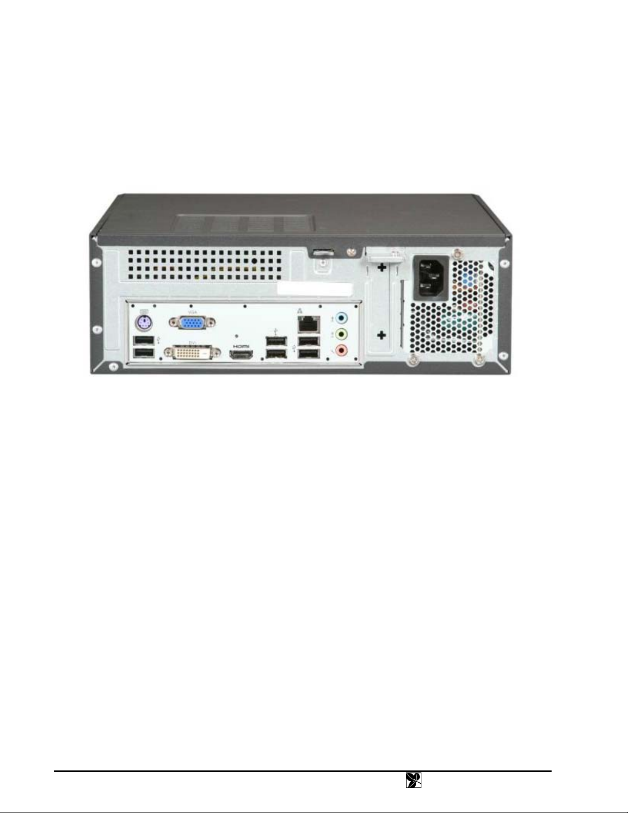
The DVX-4 installation is nothing more than connecting the power cord, keyboard, mouse, monitor., and printer.
Everything is connected internally and fully calibrated. These connections are made just like an ordinary PC. DVX-4
can be powered from AC line voltages from 90VAC to 260VAC, 50 / 60 Hz.
The On / Off switch is on the right hand side of the chassis.
Fig. 1 - DVX –4 Rear Panel
2 DVX Instruction Manual
Page 11

USING DVX
THE MAIN WINDOW
The main window displays information about the disc, a summary of all error rates, charts of each type of CIRC error,
and results of all tests. You can print any window by activating it, then clicking the printer icon in the toolbar, or
selecting File | Print in the menu.
Fig. 2 - DVX Main Window
Disc Information
Disc Type
For CDs, this can be CD-DA, CD-ROM, CD-R, or CD-RW. In the case of CD-R or CD-RW discs, the disc capacity is
also shown in minutes, i.e., 63, 74, 80, etc.
For DVDs, this can be DVD-ROM, DVD-R, DVD-RW, DVD+RW, DVD+R, or DVD+R DL.
Number of Sessions
The number of complete sessions on the disc. Each session consists of a lead-in, program area consisting of up to 99
tracks (DVDs have only one track), and lead-out.
Number of Tracks
The total number of tracks on the disc, including all sessions.
DVX Instruction Manual 3
Page 12

Format
The format of the data on the disc. It can be one of the following:
CDs --
Blank
Audio
Enhanced CD
Mode 1 Data
Mode 2 Data
Mixed Mode
Multi-Session Audio
Multi-Session Data
CD-I
DVDs --
Blank
Video
Data
In addition, Mode 1 Data discs and Mode 2 Data discs can be further qualified with the extensions ISO9660, Joliet,
HFS, or Rockridge.
Mixed Mode discs have both audio and data tracks. Multi-Session discs are formatted as if they were two separate
discs. CD-Enhanced discs have one session with audio tracks, and a second session with data tracks.
Disc ID
The Disc ID edit box in the main window is provided for the user to enter some name, work order, comment, or other
means of identifying this disc. If the disc has a volume descriptor, the Volume ID will be entered in the Disc ID field
automatically. You can overwrite this if you wish. The Disc ID will be saved with the test results and printed on the
various reports.
Block Size
The number of user bytes in each sector of a data disc. This can vary, depending on the format of the disc. Audio discs
have no sectors, so in this case it shows the number of bytes in a subcode frame, which is the same size as a sector on a
data disc.
UPC/EAN Code
Universal Product Code; usually implemented as bar code on a package, it can also be encoded into the disc Table of
Contents.
MID code
This is the manufacturers identification code. It is embedded in recordable media to identify the manufacturer of the
media.
Record Mode
The possible modes are: Disc-at-Once, Track-at-Once, Session-at-Once, Fixed Packet, Variable Packet, Not Tested,
and Unknown. Disc-at-Once means that the disc was written from start of lead-in to end of lead-out without any write
splices. Track-at-Once means that the disc has write splices at the start and end of each track. Packet mode means the
disc was written incrementally, with write splices between each packet. The size of the packets can be variable or
fixed. This information is useful for evaluating masters that will be used for duplication or replication. Only Disc-atOnce masters can be made into a glass master for replication. Also, Track-at-Once recording may cause clicks or pops
between songs. Incrementally written discs will have write splices between each packet, which can generate many
uncorrectable errors. This makes it difficult to evaluate the quality of an incrementally written disc.
This feature will only work for data discs. Audio discs do not use link blocks or track d escriptor blocks, and so it is not
possible to detect write splices. The write mode will be displayed as “Unknown” for audio discs.
4 DVX Instruction Manual
Page 13

When “Get Write Mode” is turned on in the Options Property Sheet, the write mode of the disc will be displayed in the
Disc Info dialog. This feature can be turned off by clearing the checkbox in the Options dialog.
Test Results
The main window shows a summary of all error rates, over-range alarms (Pass / Fail status), and disc Grade.
Error Rates
Error rate data is displayed in two ways: The average and peak values (over the whole disc) are displayed, as well as
totals for E22, and total E32 errors on CDs and for all DVD error types. Each error type is also shown in a graph in the
main window.
One-Second and Ten-Second Averaging (CDs Only)
When the player is testing, it will send all error parameters to DVX once every second of program time. All CD data
displayed in DVX are one-second averages. Many CD analyzers use one second samples, but the Philips Red Book
specification calls for averaging error rates over 10 seconds, so you must be careful in comparing data from different
systems. The one-second data will have higher peaks and lower valleys. The 10-second data is smoother because it is
averaged over more samples. The average values will be identical for one and ten second data. The DVX main
window displays both 1-second and 10-second peak values.
Sum1 and Sum8 Reporting (DVDs Only)
By convention, some DVD errors are reported per 1 ECC block (Error Correction Code block
), and others are reported
for 8 ECC blocks. PI bytes and PO bytes are always reported per 1 ECC block. PIE and POE errors are counted per 8
ECC blocks. PIF and POF errors are counted per 1 ECC block.
Pass / Fail Indication
If any of these error values goes over a user selectable limit, the indicator will turn red. This prov ides a simple Pass /
Fail indication of test results (See Setting Pass/Fail Criteria
on pg. 19).
Grade
A letter grade A – D, or F is assigned according to the test results. This provides a simple quantitative result without
having to deal with the detailed results. The criteria for the grading systems are explained in the section DISC
GRADING SYSTEM on pg. 18.
Subcode Skew (CD Data Discs Only)
This shows the results of the Subcode Skew test. The Q-channel subcode on a disc contains time code, called Atime,
which is used for rapid locating of specific places. This time code should be identical to the sector address contained in
the sector header of a data disc. Any discrepancy between these two values is called Subcode Skew. This type of error
can be caused by the recording system. Skew up to ± 7 sectors is allowed, but any skew will adversely affect search
times. Positive skew means that Atime is higher than the header address. Negative skew means the Atime is less than
the header address. This test applies only to data discs, as audio discs have no sector headers. DVD discs have no
subcode, so this does not apply.
Postgap (CD Data Discs Only)
Shows the results of the Postgap test. The last track on a disc must be followed by a Postgap. The Postgap contains all
zeros (or digital silence). A minimum of 150 sectors is required.
Verify
Shows the results of the Verify Disc or Verify File test. This is the total number of bytes that did not compare, or PASS
or FAIL if the Validate Clover Signature test was performed.
DVX Instruction Manual 5
Page 14

Test Controls
Start At / Stop At
Sets the start and stop points for the CIRC, PIPO, Beta/Jitter, and Verify tests. This allows you to test only portions of
a disc. Default values are the begin and end of the information area. For CDs, you can enter new values in Minutes,
Seconds, and Frames, or Physical Sectors
2
. For DVD discs, enter Logical Block Address.
Start Button
Starts the error and/or analog tests.
Stop Button
Stops the current test in progress.
MSF Button (CD Only)
Causes the START and STOP points to be displayed and entered in Minutes, Seconds, and Frames.
Sectors Button (CD Only)
Causes the START and STOP points to be displayed and entered in Physical Sectors (see Logical Blocks and Sectors
pg. 48).
Sum1, Sum8 Checkboxes (DVD Only)
These checkboxes select which tests are performed when you press START. All of the tests selected will be performed
in sequence. To measure all error rates, select Sum1 and Sum8. If you also want to perform the analog test, check
Analog also. If both tests are selected, they will be performed in the order: Sum8, then Sum1.
Analog Checkbox
If checked, will cause the Analog test to be automatically performed after the error tests. If AMM-1 is not installed,
only Beta and Jitter will be measured. Test speed is automatically set to 4X (CD) or 2X (DVD).
Analog Only Checkbox (CDs Only)
If checked, only the Analog test will be performed. This checkbox does not appear in the DVD view, because only the
analog test will be performed if the Analog box is checked and Sum1 or Sum8 are not checked.
Blank Test Checkbox
Only applicable when a blank disc is in the drive. Performs Focus and Tracking Error tests only.
QuickScan
TM
When checked, the test time is reduced by about 3½ times for CDs and 10 times for DVDs. 48X test speed on a CD
then becomes effectively 168X, and 16X DVD test speed becomes 160X. See the QuickScan
section on page 10.
The Status Bar
The status bar at the bottom of the main window shows the drive status, drive speed, and progress of the current test.
The status bar can be viewed or hidden by checking or un-checking View | Status Bar in the main menu.
The drive status shows what the DVX drive is doing at all times. When QuickScan is enabled, “QS” is appended to the
current drive speed indicator.
2
See HLogical Blocks and SectorsH on pg. 48
6 DVX Instruction Manual
Page 15

DISPLAYING ADDITIONAL DISC INFORMATION
Table of Contents
CD Discs
This shows the starting time (or physical sector number) for each track, the track length, the track type, copy permit
status, and ISRC codes for audio tracks. You can display the Start and Length times in MSF (Minutes, Seconds,
Frames) or physical sector number format.
Fig. 3 - CD Table of Contents
DVD Discs
DVD discs have only one track plus leadout, per session. Start times are shown as Logical Block Addresses.
ISRC Codes
Clicking the ISRC button in the Table of Contents view will get and display the ISRC codes if present. This applies to
audio, video, and CD Enhanced discs as well as DVD video and audio discs. ISRC codes are used to identify the
copyright owner of music selections. This information is not contained in the Table of Contents, but rather within the
music (or video) selection itself, so DVX must scan each music track or video file to read the codes.
DVX Instruction Manual 7
Page 16
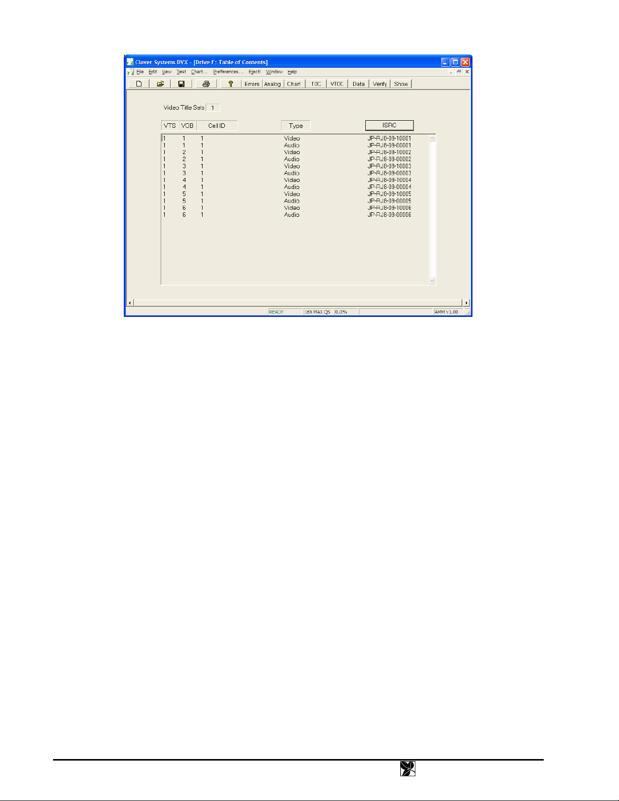
Fig. 4 - ISRC on DVD
CD Text
Pressing the View CD Text button in the Table of Contents view will display the CD Text that is recorded on the d isc.
This information can be printed using the print button in the toolbar, or File / Print in the main menu. Results can be
printed to a PDF or text file using the appropriate PDF or text print driver.
In addition, the data can be exported to an Excel spreadsheet by selecting the Export button. CD Text will be appended
to the Excel spreadsheet file CDText.xls in your My Documents / DVX Data folder.
• CD Text can then be formatted or exported to other applications.
• Current data will be added to the end of the spreadsheet. Therefore, if you wan t the data to start at row 2, you
must delete any previous data. Use the delete command, rather than clear. Clearing the data does not remove
the existing cells, it just empties them.
• You can delete any previous data in the file, but do not delete the first row, which contains the column
headers. This header row must be present for the export to work.
• The file “CDText.xls” must exist in your My Documents / DVX Data folder for export to work.
• The Excel spreadsheet file “CDText.xls” must be closed at the time of export.
8 DVX Instruction Manual
Page 17
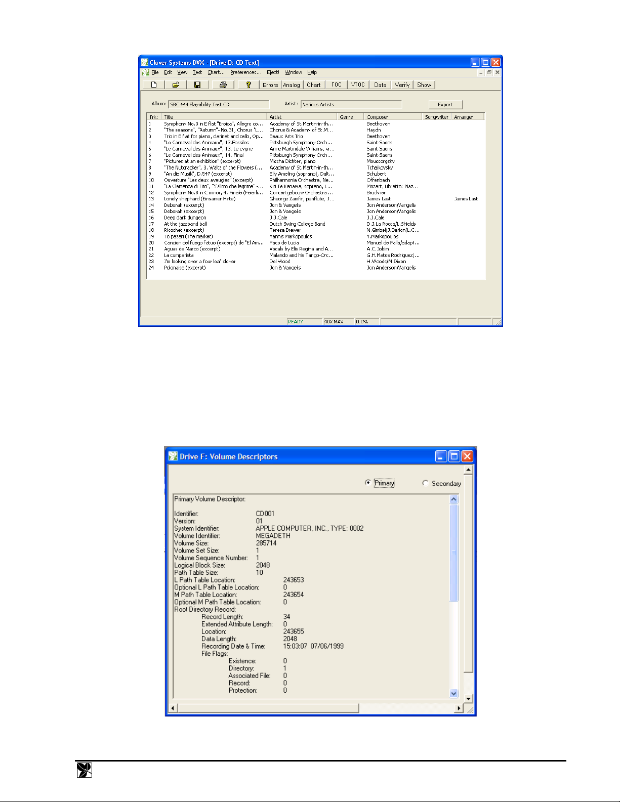
Fig. 5 - CD Text
Volume Descriptors
Selecting Vol Desc in the View menu (or VTOC button in the toolbar) will display the disc volume descriptors (all disc
types except CD-DA). In addition to the primary volume descriptor, you can display the supplementary volume
descriptor if the disc has one.
Fig. 6 - Volume Descriptor
DVX Instruction Manual 9
Page 18
Summary of Results
View | Summary opens the Summary view. This shows a complete summary of all test results. The summary can be
printed by selecting File | Print in the main menu, or clicking the print icon in the toolbar. See samples
on pg. 28.
Disc Data
The raw data on the disc can be displayed, one sector at a time. The complete contents of the sector are displayed,
including sector headers and EDC/ECC parity bytes on CDs. On DVDs, only user data is displayed. For details, see
Displaying Disc Data
on pg. 25.
SETTING OPTIONS
Drive Speed
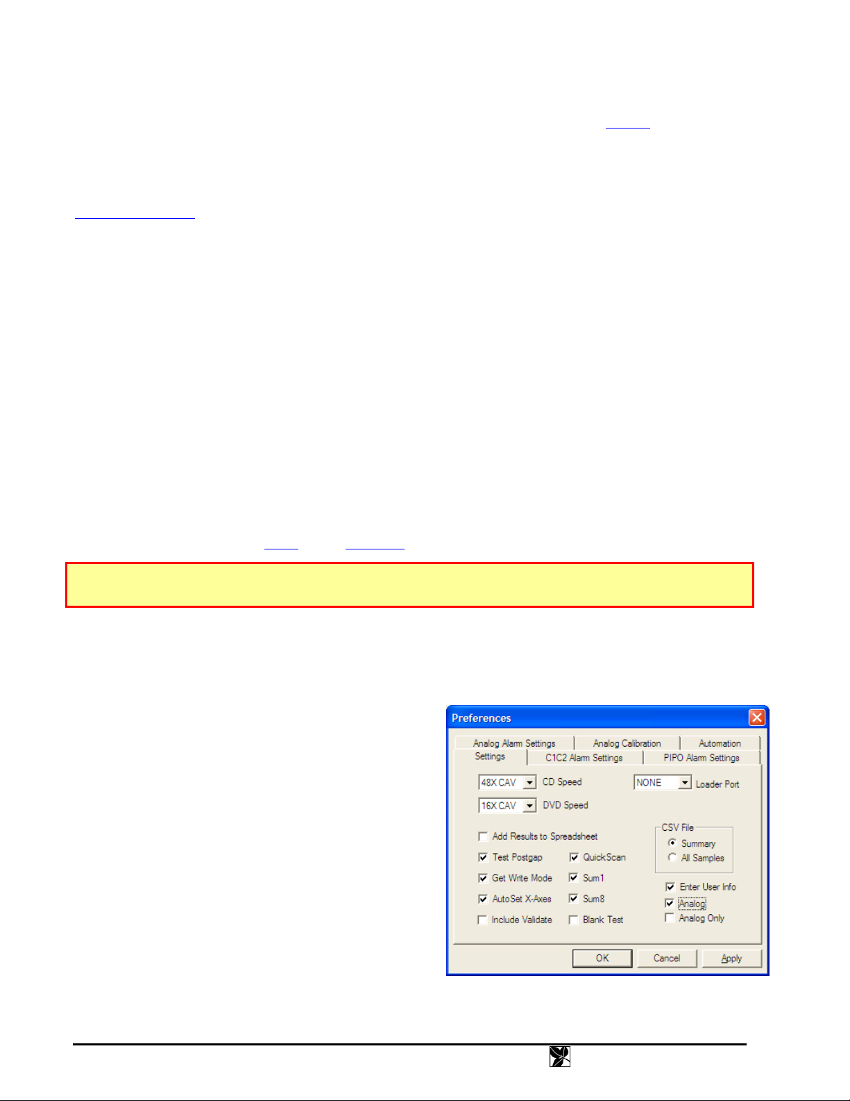
Select Preferences... in the main menu. A property sheet will appear that allows you to specify the speed o f the drive
for both DVD and CD tests, and other options.
For CD discs, you can select 4, 8, 24, 32, 40, or 48 from the drop-down list. For DVD discs, you can select 2, 5, 8, 12,
or 16 from the drop-down list. You can change the test speed at any time using this property sheet. The two lowest
speeds are CLV (Constant Linear Velocity). All other speeds are CAV (Constant Angular Velocity), which means that
the disc spins at a constant speed. Since the circumference at the outside is twice as large as at the inside, the transfer
rate at 24X CAV is 10X at the inside, and 24X at the outside (average 17X). At the 40X setting, the actual speed is
17X at the inside, and 40X at the outside (average 30X).
QuickScan
TM
DVX includes a feature that greatly increases the speed of disc testing. When QuickScan is enabled, the speed of the
test is increased by about 3½ times for CDs, and 10 times for DVDs. 48X test speed on a CD then becomes effectively
168X, and 16X DVD test speed becomes 160X. QuickScan
See the description of QuickScan below
Note: Focus Error and Tracking Error cannot be measured with QuickScan enabled.
and the TestTimes table on pg. 51.
TM
increases the speed of both error tests and Analog tests.
There are some speed limitations for both CDs and DVD discs:
1. Only single layer molded DVDs will run at 16X.
2. DVD±R and DVD±RW discs have a maximum speed
of 12X CAV.
3. DVD±R DL has a maximum speed of 8X CAV.
4. The Analog tests run only at 4X speed on CDs, and 2X
speed on DVDs.
5. In all cases, if the speed is set higher than the
maximum possible for a given test, the speed will be
set to the maximum allowed during the test. No user
intervention is required.
Choosing the Best Test Speed
In general, it is best to test at the fastest speed because good
discs will work at the highest speeds. However, some types of
defects are greatly magnified at higher speed, so you may need
to use a slower speed. Furthermore, there are no standards for
playing at high-speed. All standards apply to 1X speed only.
Some CDs and DVDs will not play satisfactorily at higher
Fig. 7 - Setting Options
speeds. DVD-ROM drives are designed to fall back to a slower
speed if they cannot read reliably, and will also re-try up to 10 times before failing. As a result, it is not obvious in
10 DVX Instruction Manual
Page 19
normal usage that a disc is not functioning at full speed. You may find discs that do not work at high speed. In this
case, lower the test speed until you can get reliable results.
If your application requires a certain throughput (like some games), DVX provides a way to confirm that the disc can
play at the required speed.
Add Results to Spreadsheet
When checked, DVX will add a summary of the test results to the end of the spreadsheet DVDTests.xls (for DVD
discs) or CDTests.xls (for CD tests). For details, see Saving Results to a Spreadsheet or Database
on pg. 14.
Test Postgap
When this is enabled, the tests will include the Postgap area of the disc. This applies to CDs only.
Get Write Mode
When checked, DVX will determine the recording method of a disc when it is loaded (except audio discs).
When checked, DVX will automatically set the horizontal axes of all graphs according to the size of the disc. When not
checked, the default value for the X axes is 80 minutes for CDs and 5 GB for DVDs. You can change the axis values
for all charts, and the settings will be remembered.
Include Validate
When checked, DVX will verify the data on the disc while performing the error test. The program will prompt you for
a Clover Signature at the start of the test. It will then attempt to validate this signature d uring the error test. The results
will be displayed in the "Verify Errors" box in the main view, and also in the Summary view. Before beginning the
test, you must create the signature from your master disc that you want to compare against. (See: CREATING OR
VALIDATING A DISC SIGNATURE on pg. 24) In automation mode, you will only be prompted once for the Clover
Signature at the beginning of the test. Each subsequ ent disc will then be validated against this signature.
Enter User Info
When checked, the user will be prompted for information related to the disc under test, when the disc is loaded. For
details, see Entering User Information
on pg 12.
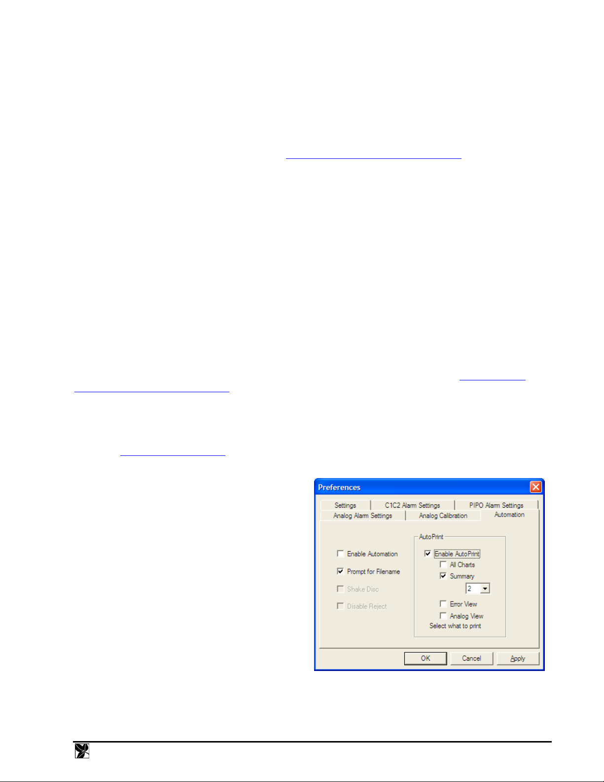
Automation
In Automation mode, the test is started automatically
when a disc is loaded, and the results can be saved
automatically without user intervention.
Enable Automation
Automation mode is enabled in the Automation property
page of the Preferences menu.
Prompt for Filename
When enabled, you will be prompted at the end of the test
for a filename for the saved results. When disabled, the
file will be saved without user input, with a made-up
unique name. You can also use the text in the user
information box #1 for the saved filename.
AutoPrint
Fig. 8 – Automation Settings
When enabled, results will automatically be printed at the
end of the test. You can select which views you wish to prin t automatically, including any or all of: All Charts;
Summary; Error View; or Analog View. When the Summary view is selected, you can choose to print either one or
DVX Instruction Manual 11
Page 20

two pages of the summary. All views can be printed at any time by selecting File | Print in the main menu, or pressing
the print icon in the toolbar.
Shake Disc
When the Autoloader is attached, you can enable this option, which will cause it to shake the disc when picking from
the input stack. Enable this if you have trouble with discs sticking together.
Disable Reject
When enabled, this will prevent the Autoloader from outputting a failed disc to the reject bin. Instead, all discs will be
output to the “good” output bin.
Table 1 - AutoSave Rules
Enter User Info Off:
Prompt for Filename Off Uses made-up filename
Prompt for Filename On Prompts for filename with default made-up name
Enter User Info On:
Prompt for Filename Off Uses User Info Box #1
Prompt for Filename On Prompts for filename with default User Info name
LOADING THE DISC
Insert a disc in the tray label side up. Press the EJECT button on the front panel, or Eject! in the main menu to load the
disc. The BUSY light will come on for a few seconds as the drive reads the Table of Contents. The Drive Status
display will show “LOAD DISC”. Wait ‘till the light goes out and Drive Status reads “READY”.
Entering User Information
You can enter up to 10 fields of user information. This can be things like work order, disc identification, publisher, or
anything else you wish. Labels describing each field are user customized.
User Info can be enabled or disabled in the Settings tab of the Preferences dialog. To enable User Info, check the
“Enter User Info” checkbox.
When enabled, the User Info dialog will appear whenever a new disc is loaded. To set up the User Info dialog, press
the “Edit Labels” button. This will allow you to edit the labels for each field. You will be prompted for a password, to
avoid unauthorized modification of the labels. The password is the same one used for entering Alarm Limits. The
default password is “Clover” (without the quotes), and is case sensitive. You can change the password by checking the
“Change” box in the password dialog. Each label can be up to 64 characters. Use the tab key to advance to the next
label. The labels will be permanently saved in the Registry.
To enable the fields you want to use, check the checkbox next to the edit box.
12 DVX Instruction Manual
Page 21
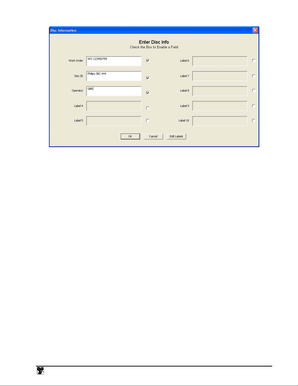
Fig. 9 - Disc Info Entry Dialog
For each disc, you can enter the appropriate information into each edit box. There is no limit to how many characters
you can enter. If the entry goes beyond the end of the box, the text will scroll to the left. You can start a new line by
pressing ENTER.
MEASURING ERROR RATES
Setting the Start and Stop Points
The “Start At:” and “Stop At:” edit boxes will default to the first sector with data, and the start of lead-out respectively,
so that the whole disc is tested. You can change the start and stop points of the test if you wish to test only a portion of
the disc. You can also select whether you want to display and enter these points in MSF format
(Minutes/Seconds/Frames), or Sector numbers (CDs only). Data discs default to display in Sectors, and audio discs
default to display in MSF. For DVDs, start and stop points are always entered in Logical Blocks Addresses.
Selecting Which Tests to Run
In the case of DVD discs, all possible measurements cannot be made at once. In the TEST group of the main DVD
view, there are four checkboxes that select which tests you want to run: Sum1, Sum8, Analog, and Blank Test.
Whichever combination of tests are selected will be run sequentially when you press Start.
Starting the Test
Click the Start button in the main window, or select Test | Main Test in the main menu. The current speed setting for
the DVX drive is displayed in the status bar. You can change it using the Settings property sheet described above. The
test will stop automatically after the specified number of sectors are tested. Progress is displayed in the status bar at the
bottom of the window.
If you wish to abort the test before it reaches the end, press Stop. When the test completes, a message box appears with
notification that the test has completed.
Saving the Results
The end of test notification prompts the operator to save the results. Selecting YES will save the data; selecting NO
will skip the save operation. The data can be saved later on by selecting File | Save in the main menu. A dialog box
prompts for a filename. You can save the data at any time, even while the test is running. Test data files use the default
file extension “.dvx” for DVD tests, and “.cdx” for CD tests, but you can use another file extension if you wish. You
DVX Instruction Manual 13
Page 22

can also enter a comment or identification string in the Disc ID edit box in the main window. This is a text string that is
printed on the Summary Printout, and can be used to identify the disc.
Saving Results to a Spreadsheet or Database
The summary of test results can be saved to a spreadsheet. This feature is enabled by setting the Add Results to
Spreadsheet checkbox in the Settings tab of the Preferences dialog. When enabled (checked), the summary results of
the main test will be appended to the end of a spreadsheet named CDTests.xls (for CDs), or DVDTests.xls (for DVDs).
The data can also be saved in Lotus 1-2-3 format: If you launch the DVX program with the command line switch “/L”
(without the quotes), the data will be saved in a Lotus spreadsheet named CDTests.wk1 or DVDTests.wk1. These files
are also included in the installation.
The results of one test are saved as one row of data. The columns are arranged as follows (next page):
14 DVX Instruction Manual
Page 23

Column CD Tests DVD Tests
1 Disc ID Disc ID
2 File Name File Name
3 Date and Time of Test Date and Time of Test
4 User Info 1 User Info 1
5 User Info 2 User Info 2
6 User Info 3 User Info 3
7 User Info 4 User Info 4
8 User Info 5 User Info 5
9 User Info 6 User Info 6
10 User Info 7 User Info 7
11 User Info 8 User Info 8
12 User Info 9 User Info 9
13 User Info 10 User Info 10
14 MID Code MID Code
15 Grade Grade
16 Pass / Fail Pass / Fail
17 AVE BLER AVE PI Bytes
18 PK BLER AVE PIE
19 10PK BLER AVE PIF
20 AVE E11 AVE PO Bytes
21 PK E11 AVE POE
22 10PK E11 AVE POF
23 AVE E21 PK PI Bytes
24 PK E21 PK PIE
25 10PK E21 PK PIF
26 AVE E31 PK PO Bytes
27 PK E31 PK POE
28 10PK E31 PK POF
29 AVE E12 TOT PI Bytes
30 PK E12 TOT PIE
31 10PK E12 TOT PIF
32 AVE E22 TOT PO Bytes
DVX Instruction Manual 15
Page 24

33 PK E22 TOT POE
34 10PK E22 TOT POF
35 TOT E22 --- NOT USED --36 AVE E32 MIN TE
37 PK E32 AVE TE
38 10PK E32 MAX TE
39 TOT E32 MIN FE
40 MIN TE AVE FE
41 AVE TE MAX FE
42 MAX TE MIN BETA
43 MIN FE AVE BETA
44 AVE FE MAX BETA
45 MAX FE MIN JITTER
46 MIN BETA AVE JITTER
47 AVE BETA MAX JITTER
48 MAX BETA *MIN REF
49 MIN JITTER *AVE REF
50 AVE JITTER *MAX REF
51 MAX JITTER *MIN Modulation
52 *MIN REF *AVE Modulation
53 *AVE REF *MAX Modulation
54 *MAX REF *MIN Resolution
55 *MIN I11/ I
56 *AVE I11/ I
57 *MAX I11/ I
58 *MIN I3/ I
59 *AVE I3/ I
60 *MAX I3/ I
*AVE Resolution
top
*MAX Resolution
top
top
top
top
top
Fig. 10 - Spreadsheet Format
* Only available if Analog Measurement Module installed
The "Disc ID" string described above will be saved in column one of the spreadsheet. Sample CDTetsts.xls and
DVDTests.xls sheets are included on the distribution disk. You can format the spreadsheet any way you want, but it
must be named CDTetsts.xls or DVDTests.xls. They must be located in the same directory where you store your test
results.
16 DVX Instruction Manual
Page 25

Note: You may edit and format the spreadsheet any way you wish, but do not modify the first row, or delete any of the
first four rows.
Pass/Fail is based on the Alarm settings set by the user. If any parameter goes over the Alarm setting, the result
becomes “**Fail**”.
In addition, the same summary of results or the complete test data can be saved to a comma-delimited text file named
CDTests.CSV or DVDTests.CSV. In the Settings property sheet of the Preferences dialog, you can select either
Summary or All Samples in the CSV File group. If you select Summary, a summary of the test results is appended to
the CSV file. The format of the data in the text files is the same as in the spreadsheet files.
If you select All Samples, every sample of every parameter will be written to the CSV file. In this case, any previous
file contents will be deleted.
These text files can then be imported into most database or spreadsheet programs. If the text file does not exist, it will
be created in the directory where the binary data is saved.
You can also export the raw data by using the Chart… command in the main menu. See SingleChart
Starting a New Test
To start the test, select the tests you want to perform, then press “Start”.
on page 20.
DVX Instruction Manual 17
Page 26

Disc Grading System
This feature provides a means of instantly evaluating a disc without looking at the individual data. There are five
different grades covering a wide range of performance: A, B, C, D, and F. Here are the criteria used to determine the
GRADE. These criteria are somewhat arbitrary, but reflect generally accepted practice in the industry.
CD Discs
GRADE A = AVE BLER over the whole disc not greater than 5.0
PK BLER not greater than 100
PK E12 not greater than 400
NO E22 ERRORS
NO E32 ERRORS
GRADE B = AVE BLER over the whole disc not greater than 50.0
NO E22 ERRORS
NO E32 ERRORS
GRADE C = AVE BLER over the whole disc not greater than 100.0
NO E32 ERRORS
REF less than 60%
/ I
less than 0.6
I
11
top
/ I
less than 0.3
I
3
top
/ I
greater than 0.7
I
3
top
MAX BETA greater than 15%
MIN BETA less than -10%
GRADE D = AVE BLER in all ten second periods is less than 220
E32 greater than 0 on Audio disc
GRADE F = AVE BLER in any ten second period is greater than 220
TOT E32 greater than 1000 on Audio disc
TOT E32 greater than 0 on data disc
REF less than 48%
/ I
less than 0.48
I
11
top
/ I
less than 0.24
I
3
top
/ I
greater than 0.84
I
3
top
MAX BETA greater than 20%
MIN BETA less than -15%
Generally, a GRADE A disc represents the best possible quality of disc. GRADE B is still an excellent disc, but not
quite perfect. GRADES A & B are good discs for any use, including the most demanding uses.
Most data publishers do not like to see BLER more than 50 or any E22 or E32 errors. Therefore, GRADES C through
F would be unacceptable for these users. However, GRADES C through D are still usable discs. The only grade that is
unacceptable is F, since this disc does not meet Red Book specifications. Still, this disc may be usable, and the data
fully recoverable.
Uncorrectable errors (E32) may not be a problem on audio discs, since the player’s interpolation circuitry will hide
these errors. Some players can interpolate over up to eight consecutive bad samples, although the sound quality may be
compro mised.
Uncorrectable errors do not necessarily make a data disc unusable either. Errors that are uncorrectable in the main
CIRC correction stage may still be corrected by the EDC/ECC sector level error correction used on most data discs.
Therefore, the data may still be recoverable, and can still verify if you are comparing to the original. Of course a disc
like this has no tolerance for additional degradation, such as scratches and fingerprints, so access time will increase and
it will soon fail.
Since there is no Red Book specification for uncorrectable errors (E32), a GRADE D disc is still considered within Red
Book specifications. data disc’s however, should have no E22 or E32 errors, as made. If the BLER exceeds 220 in any
ten-second period, the disc is outside the Red Book specifications. Grade F discs do not meet Red Book specs, and
therefore should be rejected.
18 DVX Instruction Manual
Page 27

Depending on your own requirements, you will have to decide where to draw th e line as far as what you are willing to
consider necessary and sufficient performance. Also please see the section INTERPRETING THE RESULTS
on pg.
35.
DVD Discs
GRADE A = Ave. PI Bytes over the whole disc not greater than 50
Pk. PI Bytes not greater than 250
Ave. POE not greater than 5
Pk. PIE not greater than 140
Pk. PIF not greater than 9
NO POF
NO UNCR
GRADE B = Pk. PIE not greater than 140
Ave. POE not greater than 20
Pk. PIF not greater than 14
NO POF
NO UNCR
GRADE C = Pk. POE not greater than 1100
Pk. PIF not greater than 30
NO POF
NO UNCR
MOD less than 0.6 (I
14/I14H
)
MAX BETA greater than 15%
MIN BETA less than -5%
single layer disc: REF less than 45%
REF greater than 85%
RES less than 0.15 (I
dual layer disc: RES less than 0.20 (I
REF less than 18%
REF greater than 30%
GRADE D = Pk POE greater than 1100
Pk. PIF greater than 30
GRADE F = Pk. PIE greater than 280
ANY POF
ANY UNCR
MAX BETA greater than 20%
MIN BETA less than -7.5%
MOD less than 0.48 (I
single layer disc: REF less than 36%
REF greater than 102%
RES less than 0.12 (I
dual layer disc: REF less than 14.4%
REF greater than 36%
RES less than 0.16 (I
)
3/I14
)
3/I14
14/I14H
)
3/I14
)
3/I14
)
Setting Pass / Fail Criteria
It is possible to set limits for each parameter measured. If the value for any parameter exceeds this limit, then the
corresponding indicator in the main window will turn red, indicating an over-range condition. In addition, any
parameters which went over it’s limit will be printed in red and will be rejected by the autoloader when installed. This
feature allows you to create your own “Pass/Fail” criteria.
DVX Instruction Manual 19
Page 28
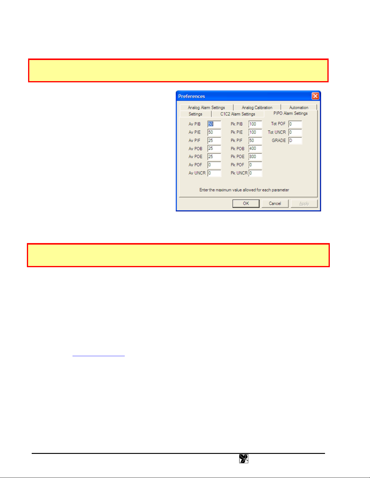
To set these limits, select Preferences in the main menu. Now select the C1C2 Alarm Settings, PIPO Alarm Settings ,
or Analog Alarm Settings tab. After making changes, press Apply or OK. The Alarm Settings are password protected
to avoid inadvertent changes. Enter your password and click “OK”.
The default password is “Clover”. The password is case sensitive.
This property sheet will allow you to enter values for
each parameter. Average value limits can be entered
with one decimal digit. Peak values of error rates,
however, must be integers. Note that the value you
enter is the maximum allowed, so that the value must be
larger than this number to generate an alarm. All alarm
settings are permanently saved when you click OK.
How Good is Good Enough?
Each user must decide what criteria to use for pass/fail.
The higher the cost of failure, the more critical you want
to be. Start with the factory defaults, then as you get
more experience, you may wish to fine-tune the settings.
Changing the Alarm Settings Password
To change the password, first enter the current
password, and then set the Change checkbox, and press
“OK”. You will now be prompted to enter a new password. After pressing OK again, you will be pro mpted to confirm
the new password. If the two entries match, the password will be changed to the new entry.
Fig. 11 - Alarm Settings Property Sheet
Note: The default password is “Clover”. The password is case sensitive, so you must type it exactly as shown (without
the quotes). If you change the password, then forget what it is, you must call the factory for instructions to recover it.
MAKING CHARTS
There are two types of charts: Single Chart, and All Chart. The Single Chart displays any or all error types in one
graph. The All Chart displays individual charts of each parameter. On charts with multiple parameters, the individual
traces will be color-coded. If you have a color printer, they will be printed in color.
Main Window Charts
The charts in the main window always display all error and analog data. You can change the axes by double-clicking
on the axis. This will open a dialog that allows you to change the axis. When Auto Set X-Axes is enabled in
Preferences… then the X-axis will be set automatically according to the length of the disc. Each chart can be
customized; see Modifying the Charts
Single Charts
To graph one or more errors or analog values in a single chart, select Chart in the main menu or toolbar. A dialog box
will appear which allows you to select which parameters you wish to display. Check the boxes of the errors you want
to display then click OK. To select a different chart, just press Chart again to bring up the selection dialog. To print
the chart, select File | Print in the main menu or click the printer icon in the toolbar.
on pg. 22.
20 DVX Instruction Manual
Page 29
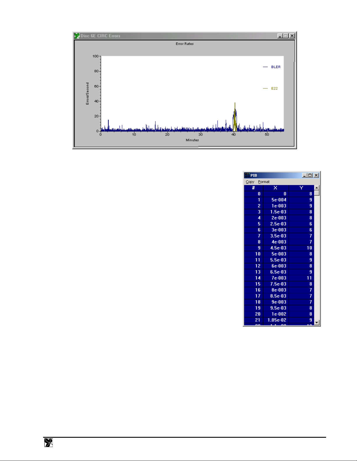
Fig. 12 - Sample Single Chart
The Single Chart graphs have some useful features: You can modify both the
horizontal and vertical axes to zoom in on detail. You can superimpose two or
more error types to see how they are correlated. These charts can be sized, and
printed at any size. All objects in the chart can be customized by double-clicking
on the object.
Double-clicking the line plot will open a dialog that allows you to change various
line attributes, and also display the data in tabular form. The resulting data table
can be copied and pasted to another application, such as a spreadsheet or database
program.
The X-Axis units are minutes (for CD), or GBytes (for DVD).
Print All Charts
This menu selection prints a page of eight individual charts of each parameter,
similar to that displayed in the main window. This group of charts allows you to
print graphs of all results on one page of paper, plus it provides a means of
printing all parameters at once with different vertical scales. The vertical and
horizontal scale can be individually set for each chart by setting the charts in the
main window. The printed charts will use the same settings as for the main
window charts.
If the Analog test has been performed, both the Error View and the Analog View
Fig. 13 - Sample Data Table
will be printed.
DVX Instruction Manual 21
Page 30
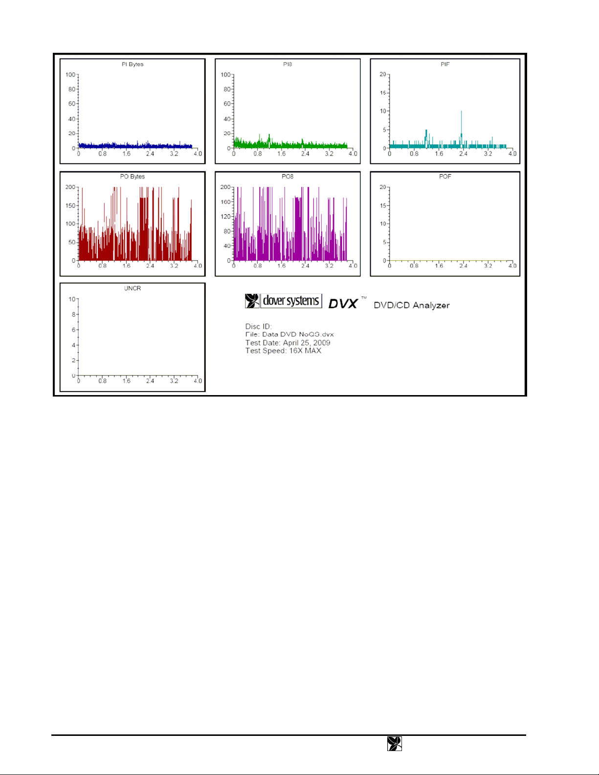
Fig. 14 - Sample All Chart
Modifying the Charts
The graphs can be modified to suit your needs. You can change both the horizontal and vertical axes to fit the data.
You can also change the line styles and colors, labels, and titles.
Changing the Axes
Double-click on the axis you want to modify. A dialog will appear that allows you to set both the minimum and
maximum values for the range of that axis. You can also set the number of major and minor tick marks. If you make
the range of the axis really large, be sure to adjust the space between tick marks accordingly. Otherwise you may
generate an axis labeled with hundreds of tick marks! You can also apply grid lines to the chart with this dialog. The
axis settings are saved for all charts, so that the next time you run DVX, it will start up with the axes set the way you
left them.
Changing the Line Style & Color
Double-click on a data plot to open the “Plot Parameters” dialog. Selecting “Line Attributes” will allow you to adjust
the color, style, and width of each data plot.
Other Chart Customization
All text, legends, background, etc. of the charts can be modified to fully customize your charts. Double-click on the
object you wish to edit.
LOADING IN SAVED DATA
Test data that has been previously saved can be loaded back in to display and print. Select File | Open from the main
menu. Enter the name of the file you want to load, or select from the list. The loaded data will overwrite any current
22 DVX Instruction Manual
Page 31

data for that drive. After loading a data file, you can make charts, print a summary, etc. just as if you had just
completed the test.
Test data created with Clover Systems CDX v2 & v3 can also be loaded.
You can double-click on a DVX data file (with extension “.dvx” or “.cdx”) to open it. If the DVX program is not
already running, it will automatically start. When the DVX program is first run, it will set the file types “.dvx” and
“.cdx” to automatically open in the DVX program. However, if some other application has already set the “.dvx” or
“.cdx” file type to use a different application, the setting will NOT be changed. Therefore, if this featu r e does not work,
you can use the View | Folder Options… menu and File Types tab in Windows Explorer to change the default
application for file type “.dvx” and “.cdx”.
The four “Most Recently Used” files will appear in the File menu. Selecting one of these will open the file.
VERIFYING DATA
Disc to Disc
Data Verification allows you to compare the data on one disc to another disc or a disc image on your hard drive. This is
useful to make sure that you have recorded the correct thing, or to verify that the recording system is working correctly.
To compare two discs, you must of course, have two DVD/CD drives installed. To compare two audio discs, both
drives must be capable of audio extraction. Some DVD/CD drives will not read audio discs reliably ("reading" is not
the same as "playing"). If you do not have two DVD/CD drives installed, you can compare a disc to a disc image on
your hard drive.
In the Test | Verify Data… dialog, select the drives you want to use. The Copy must be a DVX drive. Master can be
any DVD/CD drive or an image file. All installed DVD/CD drives will appear in the drop-down list box.
Click START to start the test. You can abort the test at any time by clicking STOP in the Verify Data dialog. Th e
current sector and number of bad bytes detected are displayed as the test progresses.
All sectors that fail to verify are listed in the window on the right. Double click on any sector in the list to view that
sector’s data.
The verify test will begin and end at the START and STOP points entered in the main window. These default to the
begin and end of the program area when you insert the disc, but you can change them to any values you wish, in either
MSF format or physical sectors (for CD) or Logical Blocks (for DVD).
Disc to Image
If you choose Image as the Master, the program prompts you for a file to compare to. The default file extension is
“.iso.” As with Verify CD, you press START to start the comparison, and can abort by pressing STOP. The current
sector and number of bad bytes are displayed.
Verify with Offset
Ordinarily, the verify test requires that the two discs are identical. However, there are some cases where there is an
offset between the two discs. To accommodate this, you can enter a value in the “Copy Offset” edit box in the Verify
dialog. The offset affects only the DVX drive (copy). The offset can be positive or negative. A positive offset means
that the copy drive starts at a later sector, whereas a negative offset means that the copy drive starts at an earlier sector.
The offset can be entered in MSF format or physical sectors, depending on the setting of the “MSF” and “Sectors” radio
buttons in the main view.
Disc copying programs do not always make an exact copy of a disc. They may change the mode, the starting point, or
other factors that do not necessarily affect the data. In these cases, the master and copy will not be identical, and
therefore will not verify. To pass this test, the copy must be identical to the master. If you wish to compare only the
data files on such discs, you can use a file compare utility. There are many available for free on the internet, or use the
DOS command “FC”. At the DOS prompt, type fc /? for instructions. Of course File Compare cannot work on Audio
discs, as there are no files.
DVX Instruction Manual 23
Page 32
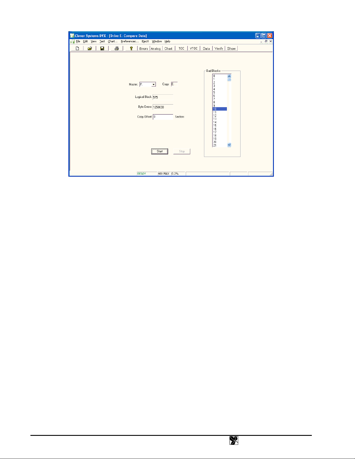
Fig. 15 - Verify View
CREATING OR VALIDATING A DISC SIGNATURE
Bit-for-bit verification between two discs confirms that the two discs are identical. DVX includes a way to validate a
copy of a disc when you don’t have the original. This is accomplished by generating a “Clover Signature” based on the
original disc data. This number is a 160-bit “Secure Hash Algorithm” that is guaranteed to be unique, based on the
contents of the disc. Additionally, it is impossible to deduce the contents of the disc based on the number, and it is
impossible for any other data to generate the same signature.
This scheme has many uses: You can verify that a disc is an exact duplicate of the original, without having the original.
You can validate a disc or copy as authentic, and confirm that the contents have not been tampered with. A Clover
Signature can be generated from the original disc, then e-mailed or otherwise transferred to anyone who needs to
validate the disc or a copy. Verifying the Clover Signature is also faster than comparing two discs, and can be
performed simultaneous with the error test.
To generate a Clover Signature, select Test | Clover Signature | Create in the main menu. Press Start in the dialog box
to start the process. You can abort the process by pressing Stop. After the data on the disc has been processed, the
Clover Number will appear in the edit box. It is a 160-bit binary number, represented by 20 hex digits. The number
will be saved with the test data if you select File | Save in the menu, or toolbar. You can also select the number using
the mouse, and press Ctl-C to copy it to the clipboard. You can then paste it into another document to mail or save.
To validate a disc, select Test | Clover Signature | Validate in the main menu. Type the Clover Signature into the edit
box, or paste it from another document. If you have a .DVX or .CDX test data file with the number saved, it will
appear in the edit box after the data has been loaded. Now press Start to validate the disc.
The Signature Verify function can also be performed during the error test. When the Include Validate box in the Setup
property page is checked, DVX will verify the data on the disc while performing the error test. The program will
prompt you for a Clover Signature at the start of the test. It will then attempt to validate this signature during the error
test. The results will be displayed (as PASS or FAIL) in the "Verify Errors" box in the main view, and also in the
Summary view. In automation mode, you will only be prompted once for the Clover Signature at the beginning of the
first test. Each subsequent disc will then be validated against this signature. If the validation fails, the disc will be
rejected. Verify during error test cannot be performed with QuickScan enabled. Therefore, Include Validate and
QuickScan are mutually exclusive.
24 DVX Instruction Manual
Page 33

Validating Audio Discs
Audio discs do not have any sectors; they are a continuous stream of audio data. Since there are no sector headers with
addresses, the only way for the drive can locate to a particular spot is by using the subcode. As there are no standards
for locating on an audio discs, different models of drives will interpret the start of a track in different ways. Therefor e,
a signature made on one model drive may not match one made on a different model drive. To use this feature on audio
discs, it is best to use the same model drive for creation and validation. In the case where the two drives are not
identical, DVX will attempt to synchronize the two drives. If successful, the offset in bytes, between the two drives
will appear in the Copy Offset edit box and the test will proceed. If DVX is unable to synchronize the two drives and
error message will appear, and the test will not be performed
Clover Signature vs. MD5
Another data validation scheme known as MD5 is commonly used to verify files. The Clover Signature uses an
algorithm devised by the National Institute of Standards and Technology, called SHA-1. SHA-1 is more secure and can
accommodate larger files (up to 2
result. Additionally, MD5 is not secure; with MD5, it is possible to change the data and still generate the same result.
64
bits) compared to MD5. MD5 produces a 128 bit result; SHA-1 produces a 160 bit
FORMAT TESTS
ISO9660
Test | Check Format | ISO9660 will check the logical formatting of a DVD or CD data disc. It checks the System
Identifiers, Volume Identifiers, Directory Identifiers, and Path Tables for correct formatting and illegal characters.
Level 1 is strict ISO9660 format, which only allows 8 + 3 file names, and limited characters. Level 2 tests to Joliet
Extension format, which allows long file names and Unicode characters.
Subcode Skew (CD Only)
Test | Check Format | Subcode starts the Subcode Skew test. The Q-channel subcode on a disc contains time code,
called Atime (short for Absolute Time), which is used for rapid locating of specific places. This time code should be
identical to the sector address contained in the sector header of a data disc. Any discrepancy between these two values
is called Subcode Skew. This type of error can be caused by the recording system. Skew up to ± 7 sectors is allowed,
but any skew will adversely affect search times. Positive skew means that Atime is higher than the header address.
Negative skew means the Atime is less than the header address.
DVD discs do not have subcode, so this test is not available.
Post Gap (CD Only)
Test | Check Format | Postgap starts the Postgap test. The last track on a disc must be followed by a Postgap. The
Postgap contains all zeros (or digital silence). A minimum of 150 sectors is required.
DISPLAYING DISC DATA
View | Data | Disc displays sector data on a disc. The current LBA (Logical Block Address) is displayed. You can
type a new LBA into the edit box, or use the PREV and NEXT buttons to select a different sector. Press ENTER after
typing a new LBA. Use the scroll bar to scroll through the data. All 2352 bytes in a CD sector, or 2048 user bytes in a
DVD sector, are displayed in hexadecimal on the left side, and as ASCII text on the right side of the window. You can
print the sector data by pressing File | Print in the main menu, or using the print icon in the toolbar.
Audio discs do not have sectors, so this window displays the section of the data stream corresponding to a subcode
frame. In this case, the logical block number you enter is the frame number from the beginning of the first track.
CD Data disc sector data is displayed as “raw” data; that is, with the sector header and parity bytes included. The first
12 bytes of every sector are a SYNC pattern that is used to locate the start of the header. It is identical on every sector
header, and consists of zero, followed by 10 FF hex bytes, followed by zero. The next four bytes are the sector header.
This consists of 3 bytes of address, and one mode byte. The address bytes are encodes in MSF format: Minutes,
Seconds, and Frames. Note that these bytes are encoded as Binary Coded Decimal, not binary. In this example, the
header address is 0 minutes, 2 seconds, 16 frames, which is logical block 16.
The mode byte can be 0, 1, or 2, and determines the size of the user data:
Mode 0: 2048 user data bytes which are all zero, + 288 auxiliary bytes which are all zero.
DVX Instruction Manual 25
Page 34
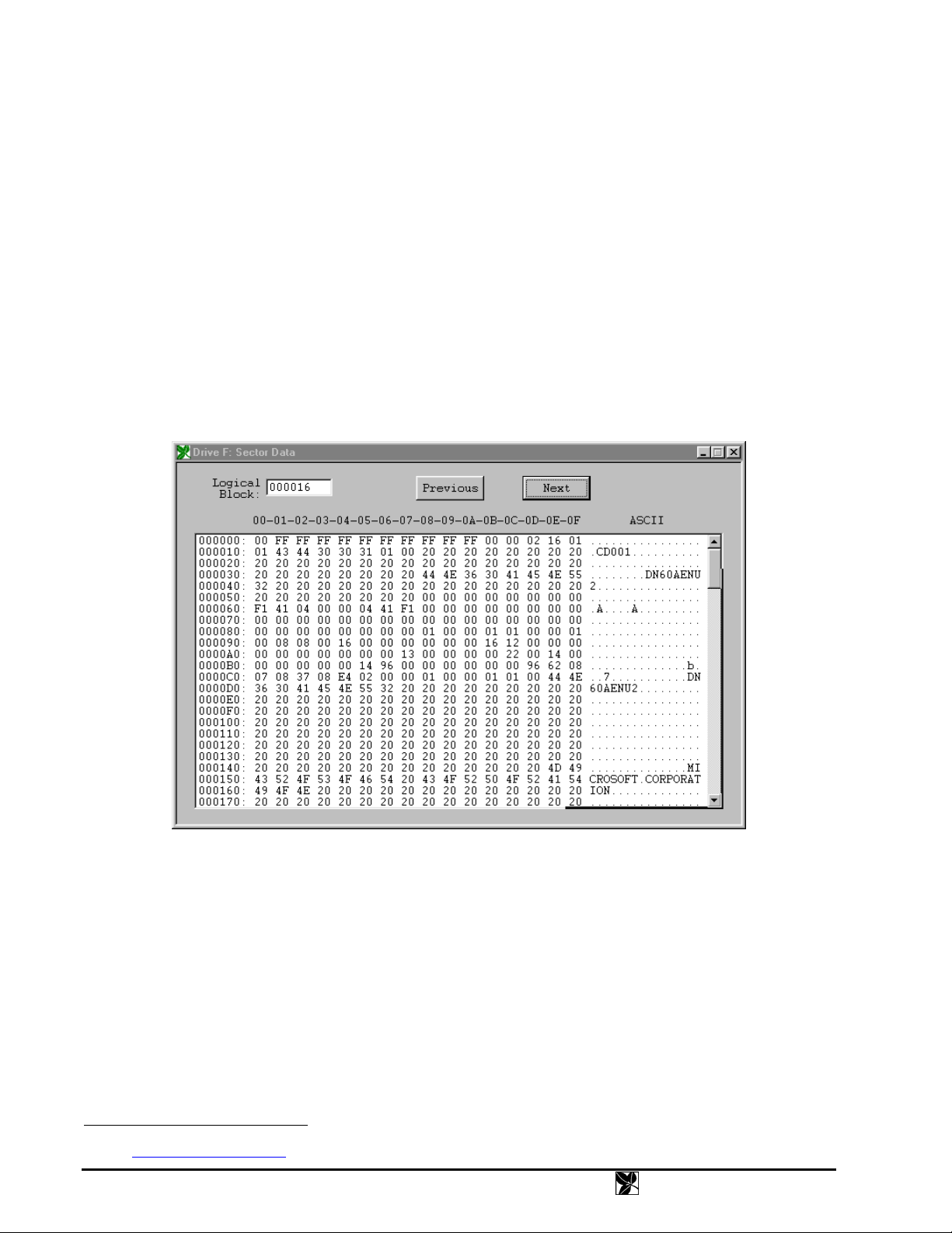
Mode 1: 2048 bytes user data, plus 288 bytes EDC and ECC error correction code. This is the ordinary data disc mode,
which provides error detection and correction beyond the CIRC error correction.
Mode 2: 2336 bytes user data; no EDC or ECC code. Typically used for multi-media; has increased user data, but no
additional error correction.
DVD discs do not display sector headers or parity bytes; only the user data.
Please note that on CDs, the sector number you enter in the View Data window is a Logical Block Address (LBA)
3
,
whereas the sector numbers displayed in the Table of Contents (Disc Info) and Start and Stop in the main window, are
Physical Sector Addresses. The numbering of physical sector addresses starts at the beginning of the program area,
whereas the Logical Block Address starts at the beginning of the user data area. The difference is due to the length of
the Pre Gap. To convert a physical address to a logical address, subtract the value shown in the Start box in the main
window (should be 150 or more). So, the first sector of user data is typically physical sector 150, which would be
logical block address 0.
DVD sectors are always displayed as Logical Block Addresses.
On CD data discs and DVDs, the first 16 sectors (0-15) are reserved for system use, so the volume descriptor is at
Logical Block Address 16, which would be physical sector 166.
Fig. 16 - Sector Data on Disc
View Data | File displays sector data in an image file on your hard disk. It works the same way as described above,
except that you select an image file to read from. Image files are saved with all sync, sector header, and parity bytes, so
they look the same as on the disc.
CREATING A DISC IMAGE
File | Create Image in the main menu prompts for a file name. The default extension is “.iso”, but you can use other
file extensions if you wish.
Click START to start saving the file. You can abort the operation by pressing CANCEL. The disc is read at the speed
set in the Preferences | Drive Settings menu, so setting the speed to maximum will speed up the operation.
The disc image files preserve all sector header and error correction bytes, not just the user data.
3
See “HLogical Blocks and SectorsH” on pg. 48
26 DVX Instruction Manual
Page 35

PRINTING
All DVX windows can be printed. Select the view you want to print, and then File | Print or File | Print Preview. Or
click on the printer icon in the toolbar. Whichever window is currently active is the one that will be printed. For
example:
Printing a Summary
You can print a summary of the test results on the printer by selecting View | Summary, then File | Print. The printed
summary consists of the results of all tests that were performed. The same information displayed in the main window
as well as the current date and time, and the filename. If you want the summary printout to have a filename, which can
be used to identify the disc, you must save the data first. If you print the summary before saving the data, there will of
course be no filename. Any parameters which exceeded the Alarm Limits will be printed in red.
You can also print the main window on the printer, which provides a graphic summary. Just select the main view, and
then select File | Print in the main menu.
Printing the Charts
Display the chart you wish to print, then select File | Print in the main menu.
A dialog box allows you to set the size and location on the paper of the chart. Please note that if you select “Actual
Size” for the chart, the size of the printed chart will be dependent on the size of the window on your desktop. In this
case, the chart will be printed at the size and shape it appears on th e monitor.
You can also print all the charts on one page of paper using the Chart | Print All Charts item in the main menu. This
command will print all the charts on one page, with date, Disc ID, Filename, and test speed. It will print in landscape
mode and fill the page. The chart axes used will be the same as set in the main window.
Any of the views can also be printed automatically at the end of the test. See AutoPrint
on pg 11.
DVX Instruction Manual 27
Page 36

Fig. 17 - Sample CD Summary Printout
DVX v3.0
Summary of Results
Date: March 27, 2009 Test Date: March 22, 2009 11:44
File: \\Loader\Documents\DVX Data\55342-5B.cdx
Disc ID:
User Entered Information:
Work Order: 123456789
Disc ID: Philips 5B.3
Operator: EB
Disc Type: CD-DA UPC/EAN: 0042281412523
Test Speed: 48X MAX (Analog Measurements are made at 4X)
QuickScan OFF MID code:
Sessions: 1 Format: Audio
Tracks: 24 Sector Size: 2352
Total Disc Length: 59:40:18
Record Mode: Unknown
CIRC Test Results:
Av BLER = 2.6 Pk BLER = 12 10Pk BLER = 4
Av E11 = 2.5 Pk E11 = 12 10Pk E11 = 4
Av E21 = 0.0 Pk E21 = 1 10Pk E21 = 0
Av E31 = 0.0 Pk E31 = 4 10Pk E31 = 0
Av E12 = 0.1 Pk E12 = 10 10Pk E12 = 1
Av E22 = 0.0 Pk E22 = 0 10Pk E22 = 0
Av E32 = 0.0 Pk E32 = 0 10Pk E32 = 0
Tot E22 = 0 Tot E32 = 0
Grade = A
Analog Test Results:
Min. Ref = 74.8% Ave. Ref = 75.1% Max. Ref = 75.4%
Min. I11 = 0.66 Ave. I11 = 0.66 Max. I11 = 0.66
Min. I3 = 0.42% Ave. I3 = 0.46% Max. I3 = 0.50%
Min. Beta = -2.6% Ave. Beta = -1.3% Max. Beta = -1.0
Blank Disc Test: Not Performed
CIRC Test *** PASSED ***
Analog Test *** PASSED ***
Data Verification Results: Not Performed
ISO9660 Format Results: Not Performed
Postgap Test Results: Not Performed
Subcode Skew Test Results: Not Performed
Clover Signature:
Page No. 1
Fig. 18 - Sample DVD Summary Printout
28 DVX Instruction Manual
Page 37

DVX v3.0
Summary of Results
Date: March 27, 2009 Test Date: March 27, 2009 10:13
File: \\Loader\Documents\DVX Data\Test1.dvx
Disc ID: DVD Test Disc
User Entered Information:
Work Order: 123456789
Disc ID: Philips SL
Operator: EB
Disc Type: DVD-ROM UPC/EAN:
Layers: 1 Track Path:
Copy Protect: None Region: 12345678
Test Speed: 16X MAX (Analog Measurements are made at 2X)
QuickScan OFF MID code:
Sessions: 1 Format: Mode 1 Data – Joliet
Tracks: 1 Sector Size: 2048
Disc Size: 515392 Sectors; 1006.6 MB
Record Mode: Disc-at-Once
PIPO Test Results:
Av PI Bytes = 8.4 Pk PI Bytes = 18 Tot PI Bytes = 33954
Av PIE = 46.2 Pk PIE = 89 Tot PIE = 185556
Av PIF = 1.4 Pk PIF = 3 Tot PIF = 5679
Av PO Bytes = 16.0 Pk PO Bytes = 93 Tot PO Bytes = 64524
Av POE = 119.8 Pk POE = 578 Tot POE = 481349
Av POF = 0.0 Pk POF = 0 Tot POF = 0
Grade = C Tot UNCR = 0
Analog Test Results:
Min. Ref = 57.5% Ave. Ref = 59.2% Max. Ref = 60.8%
Min. I14 = 0.89 Ave. I14 = 0.89 Max. I14 = 0.89
Min. I3 = 0.24% Ave. I3 = 0.24% Max. I3 = 0.25%
Min. Beta = 5.5% Ave. Beta = 6.7% Max. Beta = 8.4%
Min. Jitter = 5.1 Ave. Jitter = 5.7 Max. Jitter = 6.4
Bland Disc Test: Not Performed
PIPO Test *** FAILED ***
Pk PIE Over Limit
Av POE Over Limit
Analog Test *** PASSED ***
Data Verification Results: Not Performed
ISO9660 Format Results: Not Performed
Postgap Test Results: Not Performed
Subcode Skew Test Results: Not Performed
Page No. 1
DVX Instruction Manual 29
Page 38

CONTROLLING THE DRIVE
The DVX works just like an ordinary DVD-R/RW writer. Place the disc in the loading tray label side up. Use the
EJECT button on the right side of the front panel to open and close the tray. Although DVX is capable of recording
discs, recording uses much greater laser power than playing, so you can prolong the life of the drive by minimizing this
function.
To make your DVX last as long as possible, please do not use it for recording. Recording uses approximately 10
times more laser power as reading, and therefore will shorten the life of the laser.
MEASURING PIT GEOMETRY – THE KEY TO INTERCHANGABILITY
Unfortunately, error rates do not tell the whole story of disc quality. Measuring error rates is useful because any serious
problems will be reflected in higher error rates, and it is easy to do. But when it becomes necessary to establish the
cause of high error rates, or compatibility with different players, you must look at the pit geometry.
The primary goal of disc quality is to make sure that a disc will work in every drive, every time. The key to making th is
happen is proper pit geometry.
In order to play the disc, the player must follow the track and stay in focus as the disc turns and wobbles up and down.
This is accomplished using servo signals that are derived from the way the laser beam bounces back from the disc.
Generation of the proper servo signals is wholly dependent on the size and shape of the pits.
There are specifications for pit length, depth, and width, but you would need an electron or atomic force microscope to
, I3/
measure them! Pit geometry can be measured indirectly by looking at signals like reflectivity, I
11/Itop
CDs or reflectivity, modulation, resolution, and beta on DVDs. The jitter measurement also is related to pit quality.
, and beta on
Itop
Disc performance can only be measured by playing the disc. Unfortunately, when you measure discs by playing them
back, you are measuring the performance of the player as well as the disc! As a result, it is quite possible for discs that
measure good to have problems playing on certain players. Similarly, discs that measure badly may work fine on other
players, and even measure differently on other analyzers. Different players are variously sensitive to different
parameters such as asymmetry and tracking.
If a disc is found that won’t play or gives poor results, yet plays on another player OK, there is almost certainly
something wrong with that disc. Compatibility with all players can best be assured by making sure that the pit
geometry is close to optimum.
Pit geometry can be measured by looking at the HF signal coming from the pickup (also see INTERPRETING THE
RESULTS Pg. 35).
Analog Measurement Module
DVX-4 includes the AMM-1 Analog Measurement Module to make signal measurements related to pit geometry. The
AMM helps evaluate disc quality by automatically measuring parameters such as reflectivity, I
, I11/ I
3
top
top
, I14/I
14H
/ I
(modulation), I3/I14 (resolution) and asymmetry / beta and displaying the data in the DVX software. Together with
analyzing playback errors, this information provides a thorough analysis of disc quality.
The DVX software automatically gathers data from the AMM and displays the data as statistics and easy to read charts.
Summary of the data, along with the charts can be printed and/or saved to disk for future use.
Setting Analog Alarms
Under the Analog Alarms tab of the Preferences menu you will be able to set the individual alarms for each analog
parameter. Notice that some parameters have different entries for CD or DVD, or DVD5 (single layer) vs. DVD9 (dual
layer).
30 DVX Instruction Manual
Page 39
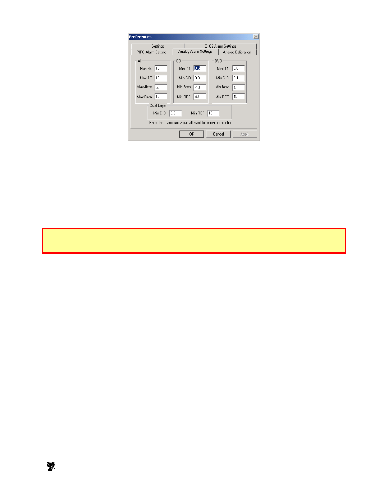
Fig. 19 - Analog Alarms Setting
Analog Calibration
Your DVX analog measurements have been calibrated at the factory, using a Philips Single Layer DVD Signal Disc,
Philips BH-1, Philips JT-1, Philips RCD-RA.1, ABEX Low Reflection CD and A-BEX TCD-W082L test discs. The
calibration constants have already been entered into the software, and you needn’t do anything further.
The required numbers are written on the DVX Final Test sheet that is included in the back of this manual. Select
Preferences… from the main menu, and select the Analog Calibration tab. If you should need to restore the settings for
any reason, just enter the values from the test form in the corresponding edit boxes, then press OK (see figure below).
The default password is “Clover”. The password is case sensitive.
IMPORTANT
Because the results can be affected by the PC (power supply voltage, temperature, etc.), it may become necessary
to re-calibrate your DVX. This can be accomplished using the test discs provided. The correct values for all
parameters are printed in the back of this manual, so you can calibrate the system by testing these discs and adjusting
the offset values in the Analog Calibration property sheet. It is not be necessary to change the gain setting, as only the
offsets are affected.
Some parameters are also affected by temperature. Therefore, DVX should be used in a temperature controlled
environment. In addition, the temperature of the laser increases as it is used, so it is best to “warm up” the DVX before
making analog measurements. The best way to do this is to play a disc for about ½ hour. Since CDs and DVDs use
different lasers, you will need to warm them up separately.
You can also calibrate the system using test discs available from Philips or others. Philips test discs are available
directly from Philips at http://www.licensing.philips.com/
Datarius, AudioDev, etc. you can use these discs as well.
It is best to use test discs with more than one measurement value, so that you know that the results are accurate over a
wide range.
If you have discs with multiple known values, you can set the gain of each parameter by comparing the difference of
the measured values to the difference of the known values. For instance, if you have two discs with known values for
Beta, such as +10 and –3, and your measured results show +8 and –2, you can then change the Beta gain by a factor
(10 + 3) / (8 + 2) = 1.3. In this example, you would multiply the current Beta gain by 1.3 to ob tain the new gain setting.
After setting the gain, you can adjust the offset. If the new gain setting produces results of +13 and 0, then you must
subtract 3 from the current offset setting.
DVX Instruction Manual 31
. If you have discs calibrated to some other standard such as
Page 40
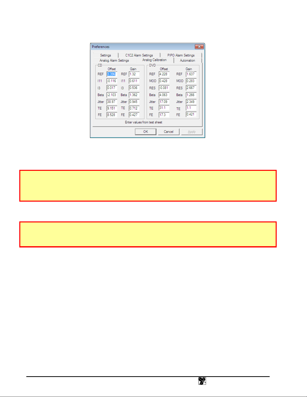
NOTE – Please note that analog measurements are very sensitive, and differences of only a fraction of a percent are
noticeable.
Fig. 20 - Analog Calibration
Making Analog Measurements with the AMM
NOTE - Measuring analog parameters must be done at constant linear velocity. The fastest speed that the drive will
play CLV is 4x for CD and 2x for DVD. Therefore, the analog tests are limited to those speeds. Enabling QuickScan
will greatly reduce the test time.
The test speed will automatically be set to the appropriate CLV speed when the test starts, an d returned to the default
speed when finished, so there is no need to set the speed.
NOTE – Focus Error and Tracking Error measurements cannot be made with QuickScan enabled. When QuickScan is
active, Focus and Tracking Error measurements will not be made.
You can view the analog test results by selecting the Analog button in the toolbar.
32 DVX Instruction Manual
Page 41
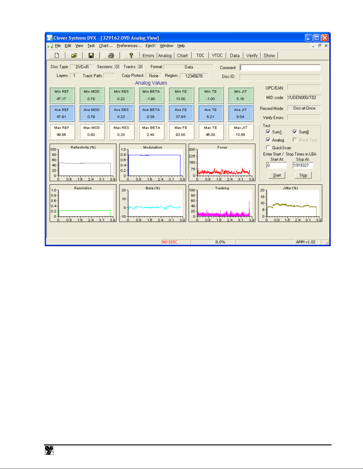
Fig. 21 - Analog View with AMM
Focus Error / Tracking Error
The Focus and Tracking error test can be performed on a blank recordable disc. When a blank disc is loaded, the Blank
Test checkbox will be enabled, otherwise it is disabled. No other tests can be performed on a blank disc.
Components of the HF Signal
The HF (High Frequency) signal coming from the pickup represents the light intensity of the beam reflected back from
the disc surface. A higher voltage represents greater light intensity, and a lower voltage represents less light. The
signal is rapidly changing between light and dark as the beam passes over the pits. When the beam is over a pit, the
light intensity is reduced. When the beam is between pits (over “land”), the light intensity is h ig her. Data is encoded in
the transitions between pits and lands.
CD HF Signal
The eight-to-fourteen (EFM) modulation scheme used produces just nine different possible lengths of pits and lands.
Therefore, the resulting HF consists of square waves of nine different durations. The signal appears sinusoidal on the
‘scope because of the limited frequency response of the optics. The “eye pattern” displayed on the oscilloscope is a
superposition of many sweeps, each consisting of up to nine different lengths. Each of the nine pit/land lengths are
exact multiples of one fundamental length, called 1T. The nine possible lengths of pits and lands are 3T, 4T, 5T, 6T,
7T, 8T, 9T, 10T, and 11T. The waveforms generated by these pits & lands are called I
respectively. I
represents the shortest pit / land, and I11 represents the longest pit or land. Generally, we only need to
3
, I4, I5, I6, I7, I8, I9, I10, and I11
3
look and the longest and shortest pits to get a good picture of pit geometry.
DVX Instruction Manual 33
Page 42
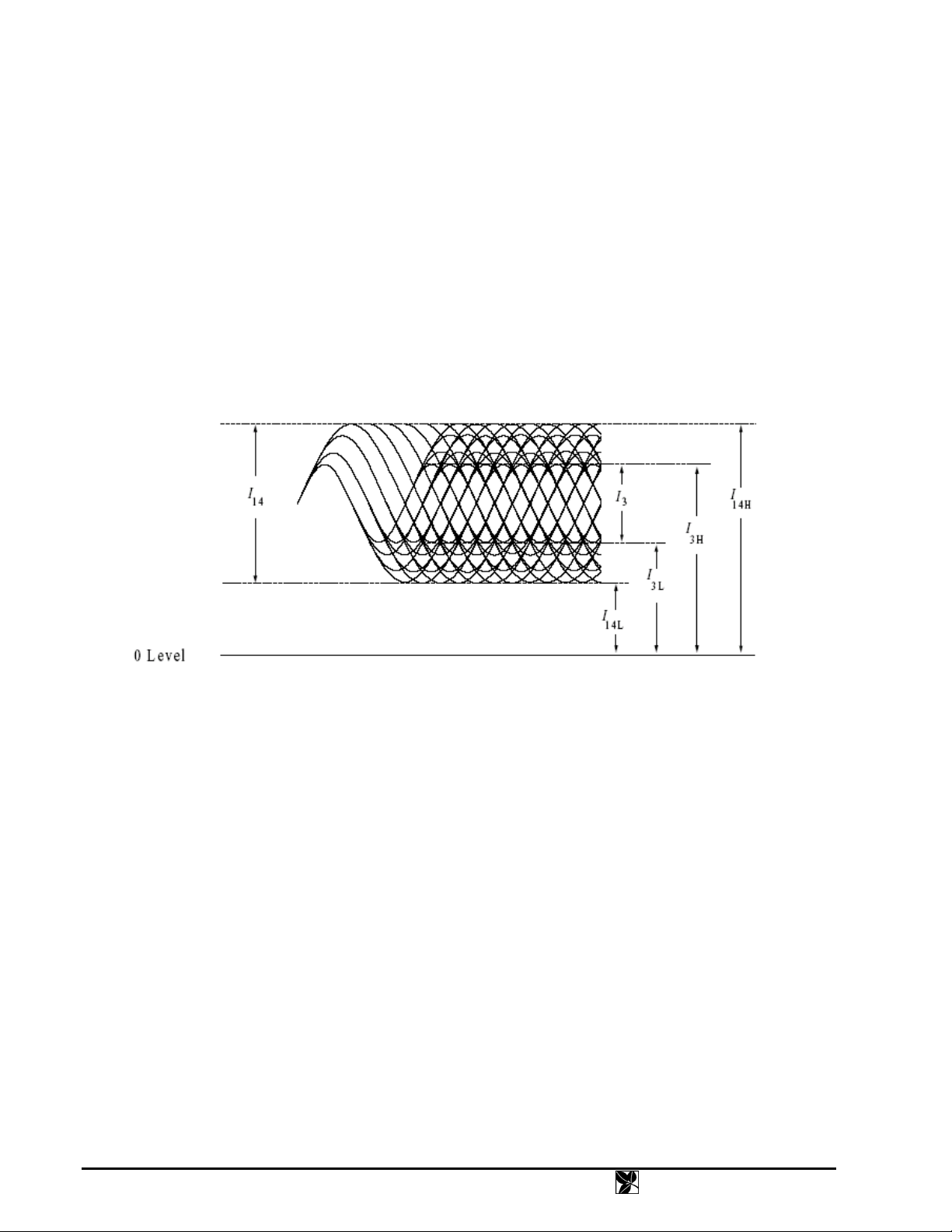
DVD HF Signal
The eight-to-sixteen (EFM+) modulation scheme used, produces eleven different possible lengths of pits and lands.
Therefore, the resulting HF consists of square waves of eleven different durations. The signal appears sinusoidal on the
‘scope because of the limited frequency response of the optics. The “eye pattern” displayed on the oscilloscope is a
superposition of many sweeps, each consisting of up to eleven different lengths. Each of the eleven pit/land lengths are
exact multiples of one fundamental length, called 1T. The eleven possible lengths of pits and lands are 3T, 4T, 5T, 6T,
7T, 8T, 9T, 10T, 12T, 13T and 14T. The waveforms generated by these pits & lands are called I
, I13, and I
I
12
respectively. I3 represents the shortest pit / land, and I14 represents the longest pit or land. Generally, we
14
, I4, I5, I6, I7, I8, I9, I10,
3
only need to look and the longest and shortest pits to get a good picture of pit geometry.
Terminology
The CD and DVD standards use different terminology to refer to the same concepts. For instance, the maximum light
level returned from the disc is called I
top in CD terminology, but is called I
in DVD terminology.
14H
Fig. 22 - DVD HF Eye Pattern
34 DVX Instruction Manual
Page 43
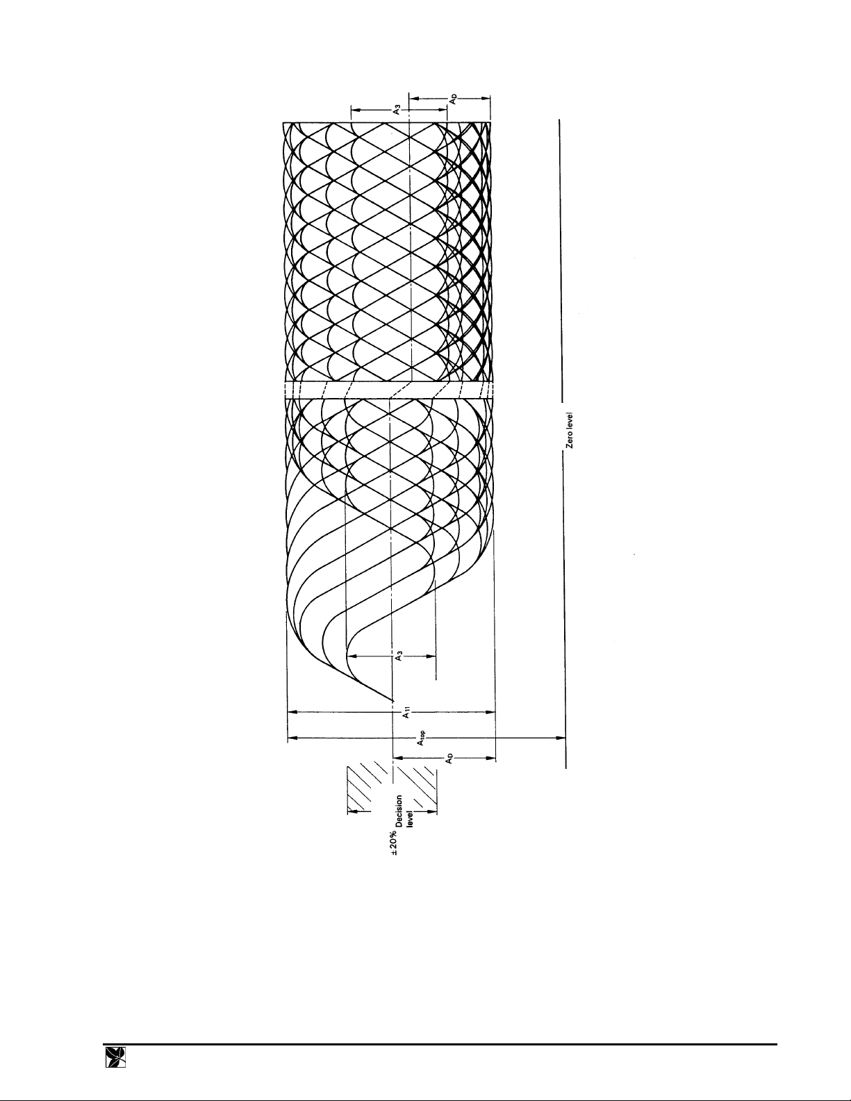
Fig. 23 - CD HF Eye Pattern
DVX Instruction Manual 35
Page 44

INTERPRETING THE RESULTS
INTERPRETING ERROR RATES
Any serious disc defects will cause an increase in the error rates. Therefore, measuring the number and severity of
errors gives a good indication of disc quality. High error rates are generally caused by local physical defects or poor pit
geometry.
Although in some sense any disc that plays without uncorrectable errors is “perfect,” there are other considerations.
For one thing, we may wish to know how close is it to getting uncorrectable errors. Obviously, a disc with very low
error rates has more tolerance for dirt, scratches, and aging before it will produce an uncorrectable error. Other discs,
although they may not produce uncorrectable errors, may be on the verge of doing so. In addition, older first
generation players may produce many uncorrectable errors on such a disc because they use a less effective error
correction algorithm than newer players do. Because the time code used to search to a location does not have CIRC
error correction, disc access times can rise dramatically with error rates, even though the data is fully recoverable.
CDs and DVDs could not work without a highly effective error detection and correction scheme. Because the pits are
so small, it is impossible to read the disc without errors. Keep in mind that the width of the pits is less than the
wavelength of light used to read them! Therefore, it is the error detection and correction codes that really make this
technology feasible. The error detection and correction code used on CDs and DVDs is known as Cross Interleave
Reed-Solomon Code (CIRC) or Reed-Solomon Product Code.
How CIRC Error Correction Works
This scheme uses two principles to achieve a remarkable ability to detect and correct errors. The first is redundancy.
This means that extra information is added, which gives you an extra chance to read it. For instance, if all data were
recorded twice, you would have twice as good a chance of recovering the correct data. The CIRC has a redundancy of
about 25%; that is, it adds about 25% additional data. This extra data is not just a repeat of the data, but is cleverly used
to record information about
have been.
the original data, which provides the ability to ded uce what the missing information must
The other principle used is interleaving. This means that the data is distributed over a relatively large physical area. If
the data were recorded sequentially, a small defect could easily wipe out an entire word. With CIRC, the bits are
interleaved before recording, and de-interleaved on playback. What happens is that the bits of individual words are
mixed up and distributed over many words. Now, to completely obliterate a single byte, you have to wipe out a large
area. Using this scheme, local defects destroy only small parts of many words, and there is always enough left of each
sample to reconstruct it. To completely wipe out a data block would require a hole in the disc of about 2 mm in
diameter.
The CIRC error correction used in CD players uses two stages of error correction called C1 and C2, with deinterleaving of the data between the stages. The error correction chip in this unit can correct two bad symbols per block
in the first stage and up to four bad symbols per block in the second stage.
Types of Errors
The error type E11 means one bad symbol (byte) was corrected in the C1 stage. E21 means two bad symbols were
corrected in the C1 stage. E31 means that there were three or more bad symbols at the C1 stage. This block is
uncorrectable at the C1 stage, and is passed to the C2 stage. Because of the de-interleaving of the data between the
stages, those three (or more) bad symbols are now in separate blocks, and so can be corrected by the C2 stage. Because
of the interleaving, one uncorrectable symbol at the C1 stage can be turned into as much as 28 bad symbols at the C2
stage. This is why E12 is typically much larger than E31.
E12 means one bad symbol was corrected in the C2 stage and E22 means two bad symbols were corrected in the C2
stage. E32 means that there were three or more bad symbols in one block at the C2 stage, and therefore this error in not
correctable.
BLER (Block Error Rate) is defined as the number of data blocks per second that contain detectable errors, at the input
of the C1 decoder. This is the most general measurement of the quality of a disc. The “Red Book” specification (IEC
908) calls for a maximum BLER of 220 per second averaged over ten seconds. Discs with higher BLER are likely to
produce uncorrectable errors. Nowadays, the best discs have average BLER below 10. A low BLER shows that the
system as a whole is performing well, and the pit geometry is good.
36 DVX Instruction Manual
Page 45

However, BLER only tells you how many errors were generated per second, it doesn’t tell you anything about the
severity of those errors. Therefore, it is important to look at all the different types of errors generated. Just because a
disc has a low BLER, doesn’t mean the disc is good. For instance, it is quite possible for a disc to have a low BLER,
but have many uncorrectable errors due to local defects. The smaller errors that are correctable in the C1 decoder are
considered random errors. Larger errors like E22 and E32 are considered burst errors and are generally caused by local
defects. As you might imagine, the sequence E11, E21, E31, E12, E22, E32 represents errors of increasing severity.
Why E32 is Considered Uncorrectable
Although it is possible under some circumstances to correct up to four bad symbols at the second stage, not all players
can do this. Until recently, most players could only correct two bad symbols at the C2 stage. For these players, E32
would be uncorrectable. In order to have a high probability of a disc working in any drive, we consider E32 an
uncorrectable error, even though some drives may be able to correct it.
This is also the rationale for not allowing E22 or E32 errors on a data disc. The earliest generation of CD players could
only correct one bad symbol at the C2 stage. As a result, an E22 error (two bad symbols at the second stage) would be
uncorrectable on these drives. In order to have the highest confidence in a data disc, it should have no E22 or E32
errors. Also, keep in mind that this requirement is for new discs, as made. Obviously, the quality will degrade with use
and age. Making discs with E22 or E32 errors does not leave adequate margin for future degradation. This is not an
onerous requirement, because with modern equipment, there is no reason to make discs with E22 or E32 errors.
How DVD Error Correction Works
DVD error correction also uses a Reed-Solomon product code for error correction. The primary difference from CD is
the size of the correction block, and the lack of interleaving.
CD error correction uses an error correction block of only 24 user bytes. CDs were designed for audio, and you don’t
want an uncorrectable block to be too noticeable. DVDs, on the other hand, use an error correction block of 32 kB. It
turns out that the error correction capability of Reed-Solomon product codes increases with the size of the block, so this
gives a much greater error correction capability, which is required due to the small size of the pits.
DVD error correction also works in two stages, but instead of C1 and C2 as on a CD, DVD error correction arranges
the data into 208 rows and 182 columns. Each row and column has it’s own parity bytes. Correction of the rows is
known as “Inner Parity” or PI. Correction of the columns is known as “Outer Parity” or PO. The rows are corrected
first, so uncorrected bytes in a row may still be corrected by the outer parity correction.
Therefore, PI Fails (PIF) are not fatal. But PO fails cannot be corrected, and should not be allowed.
Summary of Error Names
For CDs, each count of:
E11means there was one bad byte in a data frame at the C1 stage, which was corrected.
E21 means there were two bad bytes in a data frame at the C1 stage, which were corrected.
E31 means there was three or more bad bytes in a data frame at the C1 stage, which were not corrected.
E12 means there was one bad byte in a data frame at the C2 stage, which was corrected.
E22 means there were two bad bytes in a data frame at the C2 stage, which were corrected.
E32 means there were three or more bad bytes in a data frame at the C2 stage, which were not corrected.
BLER is the total number of errors encountered at the C1 stage (=E11 + E21 + E31)
AVE values displayed are the averages over the whole of the disc that has been tested.
PK values displayed are the largest one-second samples encountered over the whole of the disc that has been tested.
10PK values are the largest 10-second samples encountered over the whole of the disc that has been tested.
CD Errors are reported for each one second of program time. Since there are 7350 data frames per second, the
maximum number of errors per second is 7350.
DVX Instruction Manual 37
Page 46

For DVDs:
1 ECC block = 16 sectors = 32768 user bytes.
PI Bytes is the number of bad bytes encountered in all rows of 1 ECC block.
PIE is the number of rows in 8 ECC blocks that had errors detected by inner parity.
PIF is the number of rows that were uncorrectable by inner parity in 1 ECC block.
PO Bytes is the number of bad bytes encountered in all columns of 1 ECC block.
POE is the number of columns in 8 ECC blocks that had errors detected by outer parity.
POF is the number of columns that were uncorrectable by outer parity in 1 ECC block.
UNCR is the total number of uncorrectable ECC blocks for the whole disc.
AVE values displayed are the averages over the whole of the disc that has been tested.
PK values are the largest values encountered over the whole of the disc that has been tested.
TOT is the total number of errors encountered over the whole of the disc that has been tested.
The Reed-Solomon Product Code can correct 5 bytes per row, and 8 bytes per column. Therefore...
PI Bytes - maximum correctable = 208 rows * 5 bytes = 1040 bytes; default limit = 9.6%
PIE - maximum correctable = 208 rows * 8 blocks = 1664 rows; default limit = 6%
PIF - maximum correctable
4
= 208 rows; default limit = 24%
PO Bytes - maximum correctable = 182 columns * 8 bytes = 1456 bytes; default limit = 21%
POE - maximum correctable = 182 columns * 8 blocks = 1456 columns; default limit = 55%
POF - maximum correctable = 0; default limit = 0
UNCR - maximum correctable = 0; default limit = 0
As you can see, the default limits are generally set quite low. The only standards for DVD errors are that PIE must be
no greater than 280, and there should be no POF errors. You can set the limits as sensitive as required by your
application. It all depends on how picky you want to be. Also note that the actual correction capability depends on the
pattern of the errors. Maximum error correction capability is not always achievable.
Errors Are Not ‘Things’
Please remember that an error on a disc is not a physical thing. It is a manifestation of how well the total system (disc +
player) is working. The disc itself does not have an error rate; playing the disc produces errors.
Ideally, what you want is a disc that will play back on ALL players with a low error rate. Unfortunately, there are no
standards for players, only for the discs. Therefore, each type of player may give different results.
How to Interpret the Error Charts
The chart below shows an example of a disc that has low overall error rates, but with a localized defect. This is a good
example of why BLER by itself is not a good indicator of disc quality. The average BLER on this disc is fairly low, but
there was a burst of E22 errors at around 41 minutes, indicating a local defect at that location.
4
Depends on the data
38 DVX Instruction Manual
Page 47
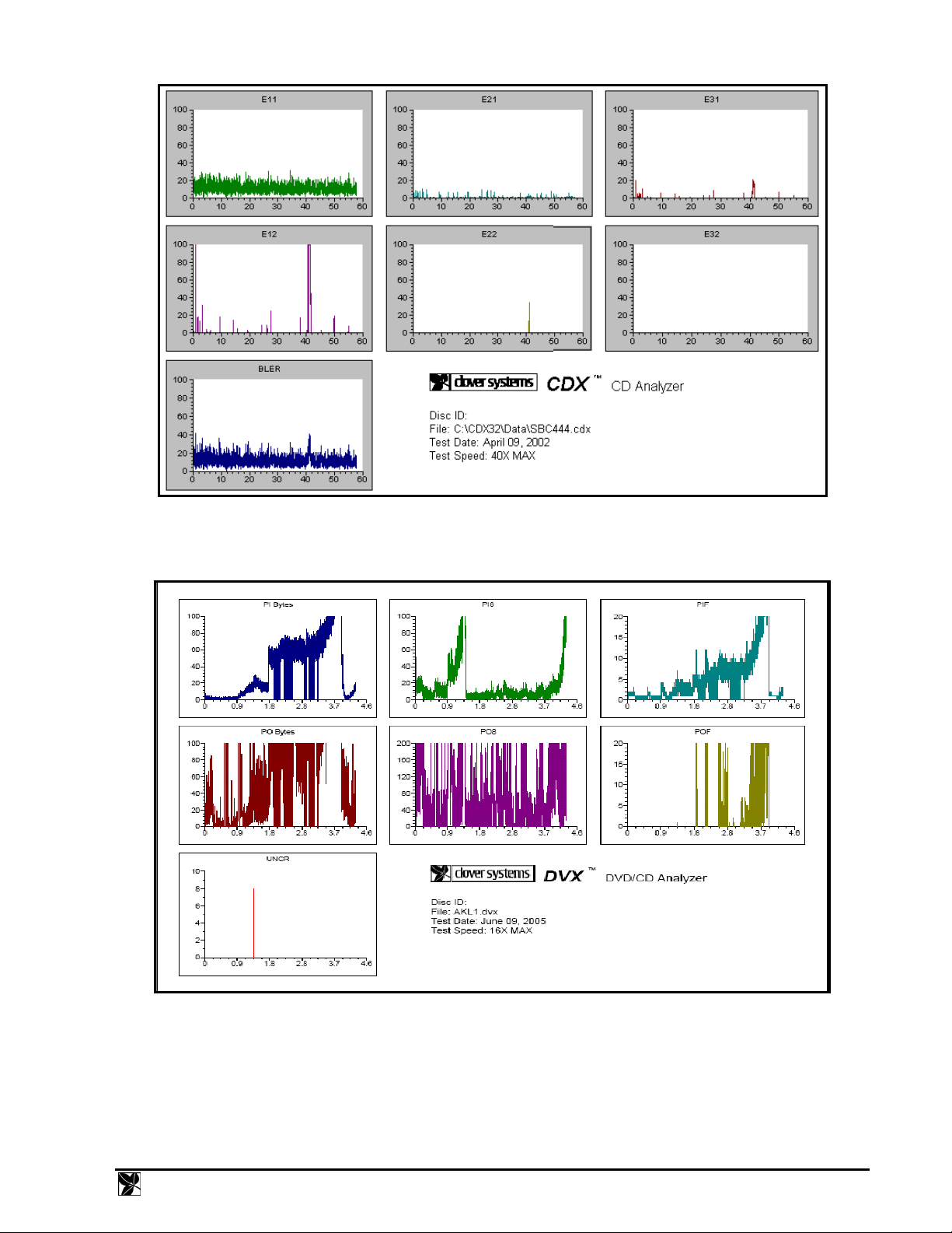
Fig. 24 - Local Defect
Fig. 25 - Global Defect
Here’s an example of a disc with global problems over a large area of the disc.
DVX Instruction Manual 39
Page 48

CD Errors
E11 errors are the smallest errors, and are essentially random. High E11 error rates can be caused by excessive jitter, or
low signal-to noise ratio. E21 errors represent slightly larger defects like dust or small scratches. E31 are again larger
defects that cannot be corrected at the first stage of error correction (C1), and are de-interleaved and passed to the
second stage (C2). De-interleaving of the data turns one E31 error burst into as many smaller errors. Each E31 error
can produce as many as 28 E12 errors. It is not possible to predict how many E12 errors will be generated for each E31
error unless you know the exact location of the bad bits. This de-interleaving explains why E12 peaks can reach many
time higher than the other errors.
E22 and E32 errors are caused by fairly large defects, or mis-tracking. A common cause of occasional E22 errors on
CD-R’s is a spec of dust on the disc while recording. This will block the recording b eam and create a vo id where there
are no pits. Recordable media should be absolutely clean when recording.
DVD Errors
DVD error correction is much more powerful due to the larger block size, but this also makes it difficult to determine
the size of defects, and very small defects will not show up as clearly as on a CD. The “Sum1” test detects the number
bad bytes in rows and columns, plus the number of uncorrectable rows and columns in one ECC block. This is the
highest resolution view, so small defects should show up best here. On a good disc, PI Bytes will represent random
errors, and so should be fairly low and uniform across the disc. This is comparable to BLER on a CD, so it gives a
general view of disc quality, but as with BLER, does not show the severity of defects. On a good disc, PIF error will
not exceed four per block, and of course there should be no POF errors.
Similar to C2 errors on a CD, the PO errors can be much larger than PI errors. For example, one PIF error means that
one row was uncorrectable, so in principle, there could be as many as 208 bad bytes in that column, so PO Bytes could
be as much as 208 times PIF.
The “Sum8” test detects the number of bad rows and columns in 8 ECC blocks. A small defect that only affects one
block will be averaged out over the 8 blocks, and therefore not appear as pr ominent. As with the Sum1 test, POE errors
can be, in principle, as much as 208 times as big as one PI error. If all 8 blocks contain PIF errors, then POE could be
as large as 1664. The upshot of this is that POE error rates are typically much higher than the others.
On a good disc, you should see PI Bytes and PIF fairly low and uniform across the disc. PO Bytes and POE will be
larger and more random, but still should be fairly uniform over the disc. Good discs should have no POF errors (see
Fig. 26 below).
40 DVX Instruction Manual
Page 49
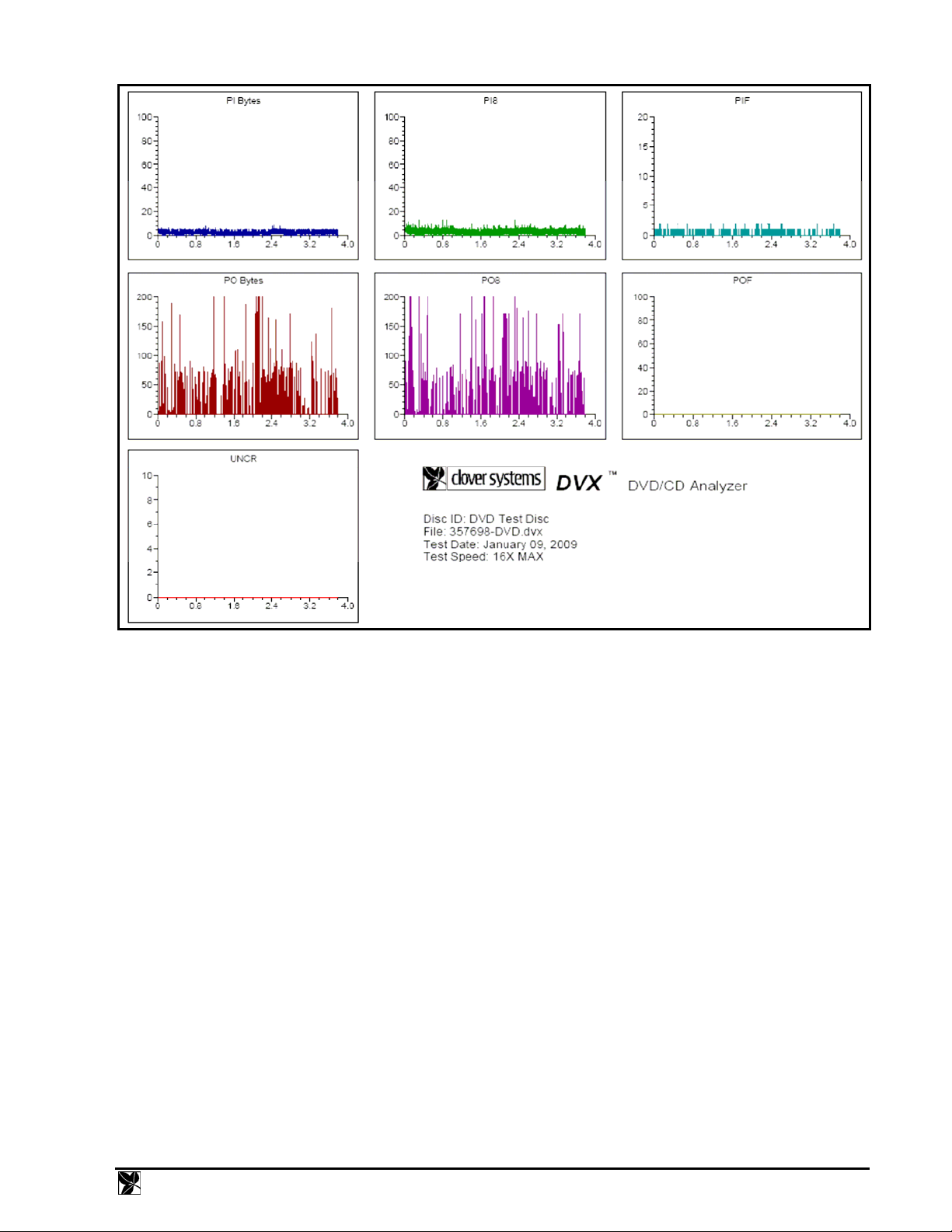
Fig. 26 - “Good” DVD
INTERPRETING HF SIGNALS ON CD
I11
This is a measure of overall signal strength. Too small of a signal makes it difficult to decode. I
by pit depth and width. As a rule, bigger I
is better, and will generally produce lower error rates. Optimum I11 is
11
about 0.67 on molded discs but can be significantly higher on recordable discs.
I
3
Represents the shortest pits and lands, and is the highest frequency part of the signal. I
is always smaller than I11
3
because the smallest pits are at the limit of resolution of the optics. Pits that are too small can cause Low I
writing speed (higher capacity discs) will make the pits shorter, and I
lower. Again, larger I3 is better, up to a point.
3
Minimum allowed is 0.30, and maximum is 0.60.
Asym & Beta
Asymmetry and Beta are two different ways of measuring the same thing. They are a measure of the relative amount of
pit and land. Zero asymmetry (or beta) means that the amount of land is the same as the amount of pit. When they are
not the same, this causes distortion of the signal that makes it hard to decode.
Although they measure the same thing, Asymmetry and Beta have opposite signs in the CD specifications. So negative
asymmetry is the same as positive beta on a CD. Asymmetry for DVDs is defined with the same sign as beta (and
opposite to CDs). CDX with AMM-1 measures Beta, so we use that convention.
is primarily affected
11
. Lower
3
This measurement is useful because it is a function of the writing power of the laser during glass mastering (or writing a
recordable disc). Higher laser power produces more positive beta. Some positive beta is desirable, with optimum of
DVX Instruction Manual 41
Page 50

0% to +5% for recordable discs, and +10% for molded discs. The maximum allowed is -5% to +15% for molded discs,
and -10% to +15% for CD-R. Beta must not vary by more than 2% over the disc. CD-Recordable discs with lo w I
and
3
negative beta are often found to give unreliable results.
Reflectivity
Reflectivity is a function of the metal reflective layer, and on recordable discs, the absorption of the dye layer that is the
active recording medium. The reflectivity of the aluminum layer is typically around 80%, but depends on the layer
thickness. Some light is absorbed by the plastic substrate, so typical values for good molded discs are around 75%.
Reflectivity of CD-R discs is usually lower, and the minimum allowed is 65%. Low reflectivity is a common problem
with recordable discs, which causes lower signal strength, making the signal harder to decode.
INTERPRETING HF SIGNALS ON DVD
HF signals on DVD discs are substantially the same as for CD, except that there are now 11 possible pit sizes (I
3
– I
)
14
instead of 9. Also, the frequency of these signals is higher due to the higher bit rate of DVD discs.
/ I
14
14H
(Modulation)
is primarily affected
14
is better, and will generally produce lower error rates. Optimum I14/I
14
14H
is
I
This is a measure of overall signal strength. Too small of a signal makes it difficult to decode. I
by pit depth and width. As a rule, bigger I
about 0.67 on molded discs.
/ I14 (Resolution)
I
3
represents the shortest pits and lands, and is the highest frequency part of the signal. I3 is always smaller than I14
I
3
because the smallest pits are at the limit of resolution of the optics. Pits that are too small can cause low I
larger I
is better. Minimum allowed I3/ I14 is 0.15 for single layer discs, and 0.20 for dual layer discs.
3
. Again,
3
Asym & Beta This is a function of the writing power of the laser during glass mastering (or writing a DVD-R). Asymmetry for
DVD is defined with the opposite sign as for CD. Therefore, positive asymmetry on a DVD corresponds to negative
asymmetry on a CD, and positive Beta. Higher laser power produces more positive asymmetry (positive beta). Some
positive asymmetry is often desirable, with optimum of 0 - 5%. The maximum allowed is -5% to +15%.
Beta measures substantially the same thing as asymmetry, and is always defined in the same way for DVD and CD.
Reflectivity
Reflectivity is a function of the metal reflective layer, and on recordable discs, the absorption of the dye layer that is the
active recording medium. The reflectivity of aluminum is typically about 80%. Some light is absorbed by the plastic
substrate, so typical values for good molded discs are around 75%. Reflectivity of recordable discs is usually lower,
and the minimum allowed is 45%. Low reflectivity makes the signal harder to decode. Dual layer discs must have
lower reflectivity, because the beam must “see” through the first layer to the second layer. Therefore, the minimum
reflectivity for dual layer discs is 18%, and the maximum is 30%.
True reflectivity is difficult to measure. What we are doing here is measuring the intensity of the laser beam reflected
from the disc. This is affected not only by the disc’s reflectivity, but also the pit geometry, due to diffraction of the
beam by the pits. As a result, discs with strange pit geometry can produce erroneous reflectivity measurements.
DVX QUALIFICATION DISCS
IMPORTANT: Do not lose these discs! They allow you to determine if your DVX is working properly.
Supplied with your unit are two Qualification discs with measured results from your DVX before it left the factory. To
confirm that your system is operating properly, test these discs and compare the results with the results we have
provided. If the results are significantly different, there may be a problem with the system. Obviously, dirt, dust, and
scratches will affect your results, so you should be careful to avoid damaging these discs. The factory results are made
42 DVX Instruction Manual
Page 51
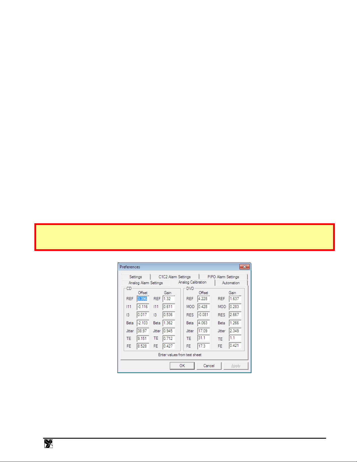
at 40X for the Setup & Qualification Discs 6F (the installation disc), and the DVD test disc is tested at 12X. All analog
measurements (Beta, Jitter, etc.) are made at 4X for CDs and 2X for DVDs.
The Setup & Qualification Disc is an ordinary CD-R disc that is known to have low error rates. Playing this disc will
confirm that the unit is capable of generating low error rates. Likewise, the DVD Qualification Disc is a DVD-R disc
with known error rates. Many subtle problems with the player can be detected using these discs.
Test results for all discs are provided in the form of graphs for the whole disc, plus summary report. You can compare
your results with the charts. These quick tests confirm that the system is capable of producing low error rates on a good
disc.
Please note that some error rates may be higher at faster speeds, and others will be higher at lower speeds. In general,
error rates on good discs will be about the same at higher speeds as at the slowest speed. Small errors such as E
E21 will not be affected much. Burst errors, on the other hand, will be greatly affected. Most burst errors (E22 & E32;
PIF & POF) are caused by disturbances to the servo systems, rather than missing data. This effect is greatly magnified
at high speed.
11 &
CALIBRATION
Your DVX analog measurements have been calibrated at the factory, using Philips Single Layer DVD Signal Disc,
Philips DVD+R Signal Disc, Philips BH-1 CD, Philips JT-1 CD, Philips RCD-RA.1, ABEX Low Reflection CD, and
ABEX Low Reflection DVD.
The required calibration constants are written on the DVX Final Test sheet that is included in the back of this manual.
In the event that the calibration constants need to be re-entered, select Preferences… from the main menu, and select the
Analog Calibration tab. Enter the values from the test form in the corresponding edit boxes, then press OK (see figure
below).
The default password for the calibration settings is “Clover”. The password is case sensitive.
Fig. 27 - Entering Calibration Constants
DVX Instruction Manual 43
Page 52

QUALITY CONTROL BASICS
WHAT IS DISC QUALITY?
We define disc quality as having every disc work in every d rive, every time, with a lifetime appropriate to the
application. You must decide what level of confidence you need for your application. The higher the cost of failure,
the more careful you want to be.
It's Worse Than You Think...
One problem in evaluating disc quality is that discs that appear "good" may not be. All CDs and DVDs have very
powerful error correction built in that hides a multitude of sins. In principle, it is possible to drill a 2mm hole through
the disc and still recover every single bit! However, you wouldn’t want to rely too heav ily on having that disc work
reliably. Many people think that just because a disc seems to be readable, it is good. But it actually may be on the
verge of failing.
WHY TEST DISCS?
DVD / CD Duplicators
You can improve profitability and reduce costly problems in your DVD-R / CD-R duplication business. As a disc
duplicator, you are responsible for the quality of your product. Data comparison does not measure disc quality. Just
because you can read it doesn’t mean it’s good. Poor disc quality can cause unreliable operation and short lifetime.
Evaluate and Qualify Recordable Media - All DVD and CD recordable media are not the same. Compatibility
between writer and media is crucial. Find out which type of media works best with your writers. In addition, anyone
can make a bad batch of media. Localized stamper defects and dye coating problems are not uncommon. Identify bad
batches of media before burning a bunch of bad discs.
Furthermore, you can discover the lowest cost media that meets your quality requirements, providing significant cost
savings.
Detect Media and Recorder Compatibility Problems - Compatibility between media, writer, and software is necessary
to produce good discs. Certain combinations of write strategy, recording speed, and media type can produce poor
results. Determining the best media to use with a given recorder (or vice versa) is greatly facilitated by testing disc
quality. Identify burners that are failing or about to fail. Discover if the problem is the media or the writer.
Manufacturers
Disc manufacturers must test discs to ensure conformance to standards & license agreements. But of course the main
goal is customer satisfaction. Many replicators have found our products useful for screening discs on the production
line to spot problems before many bad discs are made.
Distributors
Distributors can use disc testing as a way to manage quality variations from vendors, and make sure they get what they
paid for. Although most replicators produce good quality products, bad discs often slip through. Discs that are made
thinner than usual and physical defects such as pit distortion from short manufacturing cycles indicate poor
manufacturing techniques and can result in unusable discs. If you are paying for premium discs, you want to be sure
the quality measures up. In addition, you can avoid returns and unhappy customers.
Studios & publishers
Avoid problems with mastering - In the majority of glass mastering systems, uncorrectable errors (referred to as E32;
see discussion below) automatically abort the mastering session, causing costly delays for both the mastering house and
the customer. Most replicators prefer that you be able to demonstrate that your CD-R does not reach this level of error.
Provide confidence in product quality - When problems occur, they can be resolved more quickly and easily if
publishers know the quality of their discs and have a way to check them. Also, once a product is in the field, fixing a
problem becomes more difficult and expensive. Publishers can avoid returns and maintain a good reputation by
tracking the quality of their discs.
44 DVX Instruction Manual
Page 53

End Users
Critical Applications – If your application has a high cost of failure, you can increase your confidence level by testing
the discs.
Archiving – The initial quality of a disc profoundly affects its potential lifetime. A good disc has greater tolerance for
the effects of aging than a poor one. If you are archiving either DVD/CD-Recordables or replicas, you will want to
select the highest quality discs to archive. This is possible only if you h ave a way of measuring disc quality.
Avoid long access times – As discs degrade, access times increase dramatically.
HOW TO MEASURE DISC QUALITY
Traditionally, many disc producers evaluate the quality of disc copies by comparing the copy with the original. In some
cases, this can be useful, but data comparison does not measure disc quality. For instance, a bad disc can still verify.
The DVD/CDs error correction can make a bad disc work, but it may be about to fail, or may not work on all readers.
The easiest way to measure disc quality, however, is to measure error rates. This technique is effective because any
serious problems on the disc will affect error rates. A meaningful quantitative measure of disc quality can be obtained
by measuring the quantity and severity of errors generated on playback. Important information can be gleaned by
looking at the size of the errors as well as just the number. BLER (BLock Error Rate) only counts how many errors
occurred; it does not tell you anything about how severe those errors were. It is quite possible to have a low BLER, but
have serious uncorrectable errors. DVX measures six different sizes of errors, and graphs them by increasing radius,
providing a detailed picture of disc quality and defects.
Errors are not necessarily physical features on the disc, but are a measure of how well the total system (disc plus player)
works. In fact, all discs generate errors on playback - even the best discs produce thousands of errors. The errors are
partly due to the fact that playing a DVD or CD is a difficult and complicated process. The width of the pits on a disc is
smaller than the wavelength of the light used to detect them, so players are operating at th e limit of physical laws.
Playing a disc is not wholly deterministic, but is rather a statistical process. Therefore, the results will not necessarily
be the same each time.
Moreover, the objective (the lens that picks up the laser beam that reads the disc) must stay focused within a range of
less than 4 microns while the disc is moving both horizontally and vertically. The pickup must follow the spiral track
of pits as it moves to an accuracy of much less than one micron (one millionth of a meter). Several highly tuned and
sophisticated servo (control) systems are used to maintain focus, follow the track, control the spindle speed, and handle
timing issues related to reading the data. These servos are very sensitive and work only within a certain rang e. Thus,
some of the errors occur as a result of the narrow tolerances within which the equipment must function.
Two primary features of the disc itself that can cause errors are poor pit geometry and physical defects. Pit geometry
refers to the depth, width, length, and wall slope of the physical pits created in the disc. Although recordable discs do
not have pits, the recording process produces areas on the disc that function like pits and are subject to imperfections
that cause errors. Physical defects include pinholes in the reflecting layer, black spots, bubbles, and scratches. Poor pit
geometry and physical defects can make it difficult or impossible for the servomechanisms to read the data properly.
A determination can often be made as to whether problems are caused by pit geometry or local defects. A burst of large
errors confined to a small part of the disc is most likely caused by some kind of local defect. If many large errors are
found over the whole disc (or a large part of it), then the problem is most likely poor pit geometry.
It is extremely difficult to measure pit geometry directly. An easier approach is to play a disc and look at the signals
produced by the pickup. The way the light beam reflects back is influenced by the size and shape of the pits. By
observing the pattern (referred to as an “eye pattern”) created by the playback signal, it is possible to measure features
such as pit depth and length. DVX provides a simple way to make pit geometry measurements using the optional
Analog Measurement Module, or oscilloscope.
DVX Instruction Manual 45
Page 54

MAJOR CAUSES OF DISC FAILURE
The most common cause of disc failure is scratches and dirt due to handling.
With molded discs that have not been handled, the most common cause of defects is a defective master or stamper.
This is true because any defect on the stamper will be faithfully reproduced on every disc.
With DVD/CD-Recordables, the most common problem is incompatibility between the writer and the media. Often
the case is that the recording speed is too high for the type of media being used. Generally, higher recording speeds
produce poorer results. This problem usually manifests itself as high error rates across the whole disc. Another
common cause of problems is a speck of dust or dirt on the disc (readout) surface when recording. This blocks the
recording beam, producing a void, where there are no “pits”. Likewise, bubbles or black spots in the disc substrate can
cause the same problem. These type of errors show up as local defects, for example like in fig. 9 on page 22.
Quality Clues
Most problems are traceable to the disc. Often people will encounter a situation where a disc works in one drive, but
not another. The tendency is to blame the drive, concluding that “the disc must be good because it plays in this other
drive”. However, almost certainly it is the disc that is at fault. Since there are no standards for players (other than that
they must play a disc that meets the standards), a disc that is outside the Red Book or DVD specs may play on some
drives, but not others.
The solution is that all discs must conform to the standards. Discs that are made well within Red Book or DVD
standards should play on any player.
A disc that behaves erratically is invariably bad. A disc that is outside the specs (or marginal) will behave in a way that
is not predictable. If a discs produces different results each time you test it, that tells you that the disc does not meet
Red Book (or DVD) specs.
DISC DUPLICATION TIPS
How to Test Blank Media
DVX will measure Focus Error and Tracking Error on a blank disc (CD or DVD). To do this, load the disc, and wait
for it to initialize. Then select the "Blank Test" checkbox in the main screen, then press "Start".
Although some things can be measured on a blank disc, none of these things will predict how the disc will work. The
recording action is in the dye layer, and the only way to test the dye is to record on it.
We recommend that you record the full disc (74 or 80 minutes) at the speed you wish to use in production. This is
important because defects are more common at the outside of the disc. Then do the Error Test to measure the results.
Analog pit geometry measurements are especially useful for qualifying new media.
Since the media is generally quite consistent within a batch, it is only necessary to test one or two samples from each
batch of new media.
You will also find that the results vary according to the recording speed. Generally, results are worse at the highest
speeds. Ideally, you should make full test recordings at several different speeds to discover what is the highest speed
that will give satisfactory results.
Hints for Producing Good Discs
• The number one issue is compatibility between the writer and the media. There isn't necessarily a "best" writer
or "best" media; some combinations work better than others. The writer’s laser power and write strategy must
match the type of media used. Both media and writers have evolved over the years, so there are many
opportunities for mis-match.
• Use DVX to determine the best type of media for your application. Most major brands will produce good
results with modern writers. But anybody can make a bad batch. The media is pretty consistent within a
batch, so if there is a manufacturing defect, every disc will be bad. We have gotten b ad batches from most
major manufacturers. Defects range from stamper defects to bubbles in the plastic, to dirty discs and dye layer
coating problems. We have had to change brands several times over the years when a particular brand’s
46 DVX Instruction Manual
Page 55

process changed. One major advantage of having something like DVX is that you can discover what type of
media works best with your writers. You can also discover which is the lowest cost media that gives
satisfactory results. The best approach is to try several different types of media in your burners and see which
works best.
• Recording speed also makes a big difference. Again, your results will depend on the combination of writer
and media, but try each type of media at different speeds to see what works best.
• Discs must be perfectly clean when recording. One of the most common problems is a speck of dust on the
disc while recording. The speck will block the recording beam and create a “void”, where there are no “p its”.
This will show up in the test results typically as E22 errors. Since data discs should not have E22 errors, this
can be a fatal flaw.
DVX Instruction Manual 47
Page 56

APPENDIX
LOGICAL BLOCKS AND SECTORS
CD Discs
Data CDs are arranged in sectors, so that the data can be randomly accessed. These sectors are always of a fixed size,
but the amount of user data may vary. Also, each sector may contain additional parity bytes for error correction,
depending on the mode.
Audio discs have no sectors; the data is a continuous stream of music. However, they do have time code that can be
correlated to sectors. The size of a subcode frame is the same as the size of a sector on a data disc. Therefore, it is
possible to convert between Atime and Sector number.
Physical sector numbers start at the beginning of the disc, and continue to the end. However, the first 150 sectors of a
data disc are used for pre-gap, and contain no information. Therefore, the data area begins at physical sector 150, and
is called Logical Block 1. Logical Blocks (abbreviated LBA for Logical Block Address) are the same thing as physical
sectors; the only difference is that they are numbered beginning at physical sector 150. Whenever we refer to a data
disc sector, we mean physical sector unless we say logical block or LBA.
DVX software uses both physical sectors and logical block addresses. When entering START and STOP points, use
physical sectors. When viewing disc data, use logical block addresses.
DVD Discs
All DVD discs are addressed using Logical Block Addresses. DVD locations are never entered in physical sector
numbers or Minutes:Seconds:Frames.
How QuickScanTM works
QuickScanTM is an exclusive feature of DVX that speeds up testing by 3½ times for CDs and 8 to 10 times for DVDs.
This allows you to test an 80 minute CD in as little as 48 seconds, or a DVD5 in 38 seconds. The table
shows test times for various types of discs with and without QuickScan
QuickScan works by testing only samples of the disc. If the samples are very close together physically on the disc, no
significant information is lost. Serious errors are caused by physical defects that prevent the drive from reading the
data on the disc. Due to the powerful error correction on CD and DVD discs, a physical defect has to be about 100µm
in diameter to cause serious errors. Therefore, if we sample the disc every 50µm, there is no chance of missing a
significant defect. Samples are designed so that they always cover at least one complete revolution of the disc (and
usually much more). Then the pickup jumps ahead 50µm to the next sample. Any defect in the skipped section would
have to be no more than 50µm in size, and therefore would not generate any serious error. In practice, defects are
usually much larger than this, and may even include the entire disc.
QuickScan works at all test speeds. So 2X becomes 7X, 4X becomes 14X, etc. When QuickScan is enabled, the status
bar shows the current speed as “48X MAX QS” for instance instead of “48X MAX” so you can know when QuickScan
is enabled. The Summary Report also shows whether QuickScan was used for the test.
TM
.
on page 51
48 DVX Instruction Manual
Page 57
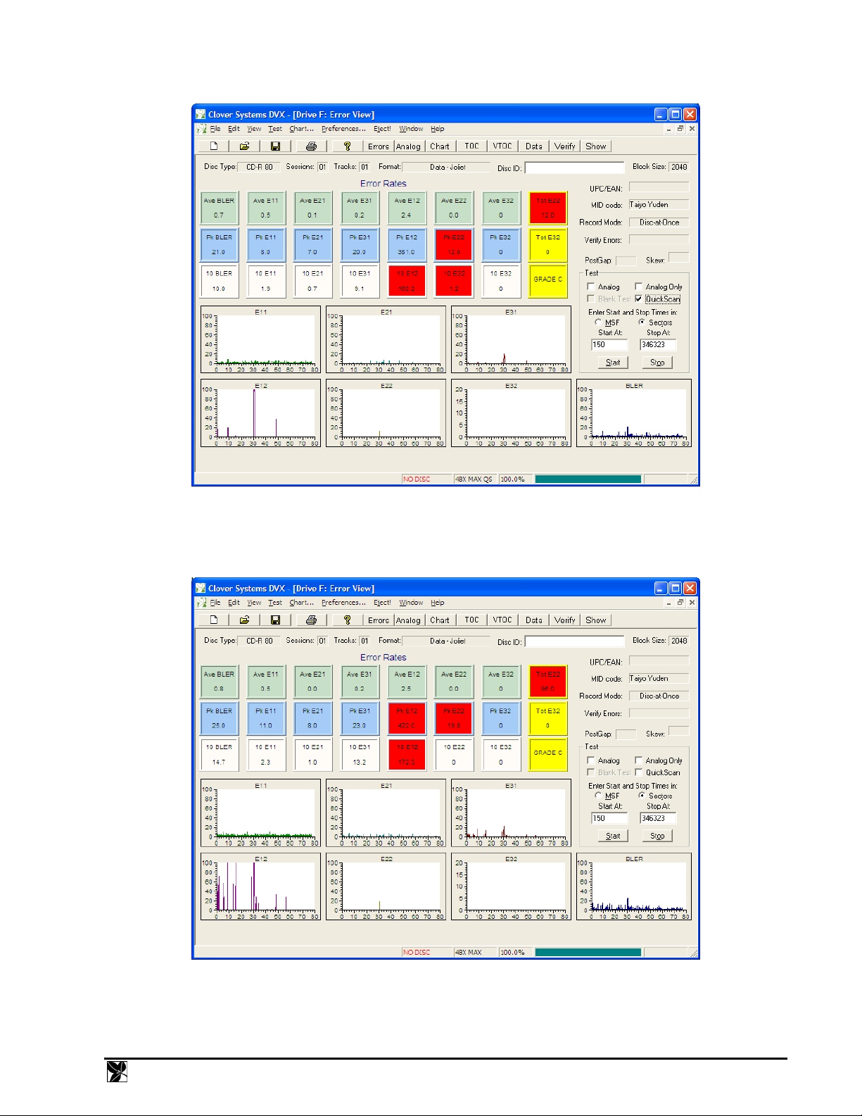
Fig. 28 - CD Error Test with QuickScan
Fig. 29 - CD Error Test without QuickScan
DVX Instruction Manual 49
Page 58
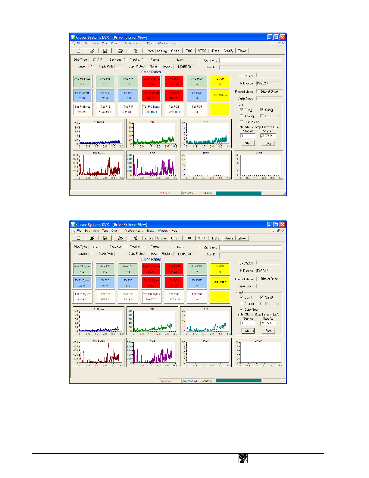
Fig. 30 - DVD Error Test without QuickScan
Fig. 31 - DVD Error Test with QuickScan
50 DVX Instruction Manual
Page 59

MAINTENANCE AND SERVICE
Ordinarily, there are no adjustments or maintenance required. If you need repairs, send the DVX to us. Call us for help
in diagnosing the problem, and to get a return authorization and shipping instructions.
Please save the original shipping carton and packing materials in case you need to ship it for any reason. If you are
unable to save the original shipping materials, you must wrap the DVX in at least 3” of bubble-pak or foam rubber
before shipping.
Service Contacts:
Tel: +1 949.598.0700
IMPORTANT
The primary thing that can go wrong with the DVX drive is that eventually the lasers will wear out. The lifetime of the
lasers varies considerably from drive to drive, so it is difficult to predict the lifetime. However, since recording discs
uses 10 times the laser power of playing back, using the DVX to record discs will shorten the laser’s life.
To make your DVX last as long as possible, please do not use it for recording. Recording uses approximately 10
times more laser power as reading, and therefore will shorten the life of the laser.
Trouble Shooting
DVX Does Not Respond
Rarely, when testing a disc that is thoroughly unreadable, the system may hang and the DVX no longer responds to
commands. Since SATA drives are intended to be “hot swappable”, the operating systems constantly polls the drive to
see if it is still there. If the drive does not respond within one second Windows thinks that the drive is disconnected and
disables it. This can be remedied by re-booting the system.
Registry Settings
The DVX installation sets registry entries for proper operation. If for some reason you need to set these manually, the
settings are:
Windows 7 / Vista / XP / 2000
[HKEY_LOCAL_MACHINE\System\CurrentControlSet\Services\ASPI32]
”ErrorControl” = dword:00000001
”Start” = dword:00000001
”Type” = dword:00000001
[HKEY_LOCAL_MACHINE\System\CurrentControlSet\Services\ASPI32\Parameters]
“Exclude Miniports” = “”
[HKEY_CURRENT_USER \ Software \ Microsoft \ Windows \ CurrentVersion \ Policies \ Explorer]
“NoDriveTypeAutoRun” = REG_DWORD: 0xB1
DVX Instruction Manual 51
Page 60
DVX Test Times
Test Type
CIRC Test
Sum8 Test
Sum1 Test
Both Tests
Analog Test
All Tests
All times are in minutes and seconds (MM:SS).
All times are for a full disc; if disc is not full, time will be proportionally less.
80 Min CD DVD 5 DVD 9 DVD±R DVD+R DL
Normal Quick Normal Quick Normal Quick Normal Quick Normal Quick
02:17 00:48
05:16 00:38 09:34 01:09 06:35 00:45 19:36 01:58
05:16 00:38 09:34 01:09 06:35 00:45 19:36 01:58
10:32 01:16 19:08 02:18 13:10 02:18 39:02 03:56
20:00 04:52 27:33 02:41 50:03 04:52 27:33 02:41 50:03 04:52
22:17 05:00 38:05 03:57 69:11 07:10 40:43 04:59 89:05 08:48
Fig. 32 – CD and DVD Test Times
SYSTEM SPECIFICATIONS
Operating System Windows 7 Ultimate
CPU Type AMD E-350 (1.6GHz, Dual-core)
Chipset North Bridge: AMD A45
Memory 1 GB DDR3 1066/800
Max Memory Supported 8GB
Expansion Slots 1 PCI Express
Storage 240 GB SATA
Graphics AMD Radeon HD6310
Audio 5.1-CH
Max LAN Speed 10/100/1000Mbps
Front Panel Ports 2 Front USB 2.0
2 Front Audio Ports
Back Panel Ports 1 PS/2
1 HDMI
1 VGA
6 USB 2.0
1 RJ45 Ethernet
Power Supply 150W
Dimensions 11.1" x 11" x 3.74"
Weight 10 lbs.
52 DVX Instruction Manual
Page 61

AC Power 90VAC – 260VAC 50/60 Hz
DRIVE SPECIFICATIONS
Ave. power consumption: 22 W
Dimensions: 5.75” x 1.63” x 7.48”
Host Interface Ultra DMA Transfer: Modes 0-4 (Ultra DMA66)
Read Speed DVD
Minimum: 2X CLV
Maximum, molded single layer disc: 6-16X CAV
Maximum, molded dual layer disc: 5-12X CAV
Maximum, DVD±R/RW: 5-12X CAV
Maximum, DVD+R DL: 3-8X CAV
Read Speed CD (all types)
Minimum: 4X CLV
Maximum: 20-48X CAV for Mode 1 Data Discs
17-40X CAV for all others
DVX Instruction Manual 53
Page 62

DRIVE ERROR CODES
If the DVX drive is unable to complete a command, it may display an error code and message. The error code has three
parts: The digit is the Sense Code. The next two digits are the Additional Sense Code (ASC), and the last two digits are
the Additional Sense Code Qualifier (ASCQ).
EXAMPLE: Error 30000
Sense Code = 3 (Medium Error)
Additional Sense Code = 00
Additional Sense Code Qualifier = 00
The Sense Code is described in the error message. The ASC and ASCQ provide additional details to pinpoint the cause
of the problem. If ASC = 00 and ASCQ = 00, it means that the cause of the problem cannot be determined. The
example error code means that the disc is unreadable for unknown reasons.
The following table lists the additional sense codes and additional sense code qualifiers.
Sense Code (ASC) and Additional Sense Code Qualifier (ASCQ) Descriptions
For Sense Key RECOVERED ERROR (1):
ASC ASCQ Description
-------------------------------------------------------------------------------18 03 RECOVERED DATA WITH CIRC
18 04 RECOVERED DATA WITH L-EC
For Sense Key NOT READY (2):
ASC ASCQ Description
-------------------------------------------------------------------------------04 00 LOGICAL UNIT NOT READY, CAUSE NOT REPORTABLE
3A 00 MEDIUM NOT PRESENT
3A 01 MEDIUM NOT PRESENT TRAY CLOSE
3A 02 MEDIUM NOT PRESENT TRAY OPEN
57 00 UNABLE TO RECOVER TABLE-OF-CONTENTS
53 00 MEDIA LOAD/IEJECT FAILED
04 01 LOGICAL UNIT IS IN PROGRESS OF BECOMING READY
(TABLE-OF-CONTENTS READ IN PROGRESS)
54 DVX Instruction Manual
Page 63

For Sense Key MEDIUM ERROR (3):
ASC ASCQ Description
-------------------------------------------------------------------------------00 14 AUDIO PLAY OPERATION STOPPED DUE TO ERROR
02 00 NO SEEK COMPLETE
02 80 SERVO SEEK ERROR
02 81 SYNC ERROR
02 82 HEADER ERROR
02 83 TARGET NOT MET
06 00 NO REFERENCE POSITION FOUND
11 05 L-EC UNCORRECTABLE ERROR
11 06 CIRC UNRECOVERED ERROR
For Sense Key HARDWARE ERROR (4).
ASC ASCQ Description
-------------------------------------------------------------------------------08 00 LOGICAL UNIT COMMUNICATION FAILURE
09 00 TRACKING FOLLOW FAILURE
09 01 TRACKING SERVO FAILURE
09 02 FOCUS SERVO FAILURE
09 03 SPINDLE SERVO FAILURE
1B 00 TRANSFER ERROR
40 00 DIAGNOSTIC FAILURE ON COMPONENT O (INTERNAL BUS FAILURE)
44 00 INTERNAL TARGET FAILURE
B6 00 MEDIA LOAD MECHANISM FAILED
For Sense Key ILLEGAL REQUEST (5):
ASC ASCQ Description
--------------------------------------------------------------------------------
20 00 INVALID COMMAND OPERATION CODE
21 00 LOGICAL BLOCK ADDRESS OUT OF RANGE
24 00 INVALID FIELD IN CDB
25 00 LOGICAL UNIT NOT SUPPORTED
26 00 INVALID FIELD IN PARAMETER LIST
53 02 MEDIUM REMOVAL PREVENT
81 00 LOGICAL UNIT IS RESERVED
63 00 END OF USER AREA ENCOUNTERED ON THIS TRACK
64 00 ILLEGAL MODE FOR THIS TRACK
85 00 AUDIO ADDRESS NOT VALID
DVX Instruction Manual 55
Page 64

For Sense Key UNIT ATTENTION (6):
ASC ASCQ Description
-------------------------------------------------------------------------------28 00 NOT READY TO READY TRANSITION
29 00 POWER ON, RESET OR BUS DEVICE RESET OCCURRED
2A 01 MODE PARAMETER CHANGED
For Sense Key ABORTED COMMAND (B):
ASC ASCQ Description
-------------------------------------------------------------------------------43 00 MESSAGE ERROR
45 00 SELECT/RESELECT FAILURE
48 00 INITIATOR DETECTED ERROR MESSAGE RECEIVED
49 00 INVALID MESSAGE ERROR
4E 00 OVERLAPPED COMMAND ATTEMPTED
B9 00 AUDIO PLAY OPERATION ABORTED
56 DVX Instruction Manual
Page 65

GLOSSARY
ATime (Absolute Time) Timecode encoded in the subchannel of a CD in the form of playing time at 1X in
minutes, seconds, and frames from beginning of the program area.
ATIP (Absolute Time In Pregroove) Samde as ATime but encoded in the pregroove and used by a writer to
locate position on an unrecorded disc.
BLER (BLock Error Rate) The total number of errors encountered at the C1 stage (=E11 + E21 +
E31)
CAV (Constant Angular Velocity) The disc rotates at a fixed RPM. This results in a variable data rate, as
the discs are recorded with CLV. Data rate is higher at the outside of the disc.
CD-DA (CD-Digital Audio) Audio disc using 16 bit linear streaming data to represent each digital sample of
two audio channels. CD-DA discs do not have sectors.
CD-R (CD-Recordable) Write once-read many disc specified by the Orange Book Part II. It uses a molded
in pre-groove to guide the laser during recording. The laser makes marks in the dye polymer layer by
heating.
CD-ROM (CD-Read Only Memory) Data discs made according to the Philips/Sony Yellow Book. This term is
often used to signify a molded disc as opposed to a CD-R disc.
CD-ROM XA (CD-ROM eXtended Architecture) A data disc that includes a subheader to support various modes of
interleaving audio, graphics, video and computer data using CD- ROM XA Mode 2/Form 1 and CDROM XA Mode 2/Form 2 sectors. Error correction capability depends on the mode and form of the
data.
CD-RW (CD-ReWritable) Re-Writable disc made according to Orange Book Part III that can be recorded,
erased, or overwritten. Uses a pre-groove like CD-R, but recording mechanism is phase change. Heat
from the laser changes the medium from crystalline to amorphous structure, which has lower
reflectivity. CD-RW reflectivity is much lower than CD-R, so not all drives can read these discs.
CIRC (Cross Interleave Reed-Solomon Code) A method of error detection and correction employing parity
bytes together with interleaving. Interleaving distributes the d ata over a relatively large area of the
disc, so that one large defect becomes many small defects after de-interleaving. C1 is the first stage
of error correction, followed by de-interleave and C2 the correction stage.
CLV (Constant Linear Velocity) The scanning speed of the laser over the pits is constant. All CDs and
DVDs are formatted this way. This requires higher rotational speed at the inside of the disc, and
lower speed at the outer tracks. This produces a constant data rate.
DAO (Disc At Once) Recording method where the entire disc contents are recorded in one continuous
operation. Molded discs are always recorded using this method.
E11 One bad byte in a data frame at the C1 stage, which was corrected (CD Only).
E21 Two bad bytes in a data frame at the C1 stage, which were corrected (CD Only).
E31 Three or more bad bytes in a data frame at the C1 stage, which were not corrected (CD Only).
E12 One bad byte in a data frame at the C2 stage, which was corrected (CD Only).
E22 Two bad bytes in a data frame at the C2 stage, which were corrected (CD Only).
E32 Three or more bad bytes in a data frame at the C2 stage, which were not corrected (CD Only).
EDC / ECC (Error Detection Code / Error Correction Code ) Additional error correction data that is added to
data CDs, providing an additional layer of error correction in addition to CIRC.
ECC Block On a DVD disc, this refers to one Reed-Solomon Product code error correction block. 1 ECC block =
16 sectors = 32768 user bytes.
EFM (Eight-to-Fourteen Modulation) Modulation scheme used by CDs; converts eight data bits to
fourteen channel bits prior to recording.
DVX Instruction Manual 57
Page 66

EYE PATTERN The HF signal from the pickup as displayed on an oscilloscope.
GB (Gigabyte) 1 GB equals 1024 megabytes. Often, 1 GB is defined as 1000 megabytes. Usage varies.
GRADE Letter A, B, C, D, F indicating disc quality, assigned based on the test results. There are no standards
for assigning letter grades.
HF (High Frequency) This refers to the signal from the pickup’s light detector that corresponds to the
pits and lands on the disc.
ISO9660 Data format specification for data discs.
ISRC (International Standard Recording Code)
Jitter Variation in the detected lengths of the pits and lands upon playback.
kB (Kilobyte), 1 kB equals 1024 bytes.
Land The area of the disc that is not pits.
LBA (Logical Block Address) Address of a sector on a data disc. Sectors are numbered consecutively
starting with 0 at the beginning of the data area.
Lead-In Area at the beginning (inside) of a disc containing the Table of Contents (TOC).
Lead-Out Buffer area following the Program Area used in case the player reads past the end of the track.
Multisession Each session is like a complete disc, with lead-in, program area, and lead-out, so a multi-session disc
is like two or more discs spliced together.
PI Bytes Number of bad bytes encountered in all rows of 1 ECC block (DVD only).
PIE Number of rows in 8 ECC blocks that had errors detected by inner parity (DVD only). Sometimes
called PIE or PIE8
PIF Number of rows that were uncorrectable by inner parity in 1 ECC block (DVD only).
PO Bytes Number of bad bytes encountered in all columns of 1 ECC block (DVD only).
POE Number of columns in 8 ECC blocks that had errors detected by outer parity (DVD only).
POF Number of columns that were uncorrectable by outer parity in 1 ECC block (DVD only).
Pit Information is recorded as a series of pits and lands. Pits appear darker than land on playback.
Viewed from the readout side, pits are actually bumps. A transition between pit and land (or land and
pit) is a one, and everything else is a zero.
Post-Gap Two second area at the end of a CD program area or Mode change, encoded as null data or audio
silence.
Pre-Gap Two second first part of a CD program area or track, normally encoded as null data or audio silence.
Red Book Proprietary Philips/Sony specification (red cover) for CD-Audio, subsequently published as IEC 908.
Reed-Solomon Code Byte-structured parity format used for error detection and correction on optical and magnetic
media.
Reflectivity The percentage of light that is reflected from the disc surface.
SAO (Session At Once) Recording method where one complete session of a multi-session disc is recorded
in one continuous operation.
Sector Fixed size unit of data on a data disc. Starts with a sector header containing the sector address.
SHA-1 (Secure Hash Algorithm –1) Derives a 160 bit word based on a block of data, which can be up to 2
64
bits. This word is unique to this data set; changing any bit (or combination of bits) will change the
result.
Skew (Subcode Skew) The difference between a sector address contained in a sector header, and the Atime
contained in the subcode.
58 DVX Instruction Manual
Page 67

Subcode Ninety-eight-bit codes used in the CD format. P and Q codes contain flag and control information.
Timecode (Atime) is encoded in the Q channel. Codes R,S,T,U,V,W may be used for CD+G or other
specialized applications.
Table of Contents (TOC) Lists number of CD tracks, their starting locations, total length of data on the disc, and
identification of type of disc. The TOC is placed in Q-subcode in the lead-in area of a CD disc.
TAO (Track At Once) Recording method where one track is recorded. Lead-in and lead-out are added
later.
UPC/EAN (Universal Product Code / European Article Numbering) A code identifying a consumer product.
Usually appears as a bar code on the package, and can be encoded into a CD.
UNCR Total number of uncorrectable ECC blocks for the whole disc (DVD only).
Volume Descriptor Up to four sectors containing information describing the disc information.
Write Mode Method used to record a recordable disc: Can be TAO (track-at-once), SAO (session-at-once), or
DAO (disc-at-once).
DVX Instruction Manual 59
Page 68

INDEX
Alarm Settings, 20
Analog Measurement Module, 16, 18, 19, 30, 32,
45
Automation, 11
BLER, 1, 15, 18, 36, 37
CIRC errors, 1
Clover Signature, 11, 24, 25, 28
CLOVER.WK1, 14, 16, 17
DISC DATA, 25
Disc ID, 4, 14, 15, 16, 27
DISC IMAGE, 26
EDC/ECC, 18
ERROR CODES, 54
Error Names, 37
Eye Pattern, 34, 35
Grade, 1, 5, 15, 19
INSTALLATION, 2
ISO9660, 25
ISRC Codes, 7
LBA. See Logical Blocks
Logical Blocks, 48
Pass / Fail, 5, 15, 20
Physical sector, 48
Postgap, 5, 25
PRINTING, 27
QUALIFICATION DISCS, 42
QuickScan, 1, 6, 10, 24, 48, 49, 50, 52
Record Mode, 4
Red Book, 5, 18, 36
Reflectivity, 42
Registry, 51
SERVICE, 51
Spreadsheet, 11, 14
Subcode Skew, 5, 25
Table of Contents, 4, 7, 12, 26
UPC/EAN, 4
Verify, 5, 6, 23
Volume Descriptors, 9
Write Mode, 5, 11
DVX Instruction Manual 61
 Loading...