

Page 1

CDC6 Specification
Cloud drive intelligent technology Co.,Ltd
Page 2

Cloud drive intelligent technology Co.,Ltd
Page 1 of 23
Contents
1. About the user manual............................................................................................................... 3
2. Material and external dimensions..............................................................................................3
Real product.................................................................................................................................. 3
Dimension figure: (unit: mm)........................................................................................................4
3. Function summary.....................................................................................................................5
4. Button definition........................................................................................................................7
5. Installation instructions............................................................................................................. 7
6. Normal operation.......................................................................................................................8
(1) Display on/off.......................................................................................................................... 8
(2) Turn on/off of front lights........................................................................................................ 9
(3) Opening/closing of USB charging function.............................................................................9
(4) PAS level selection and 6Km/h implementation mode......................................................... 10
(5) Display interface.................................................................................................................... 10
(6) Battery power indication........................................................................................................12
(7) Error code definition..............................................................................................................12
(8) Motor power indication......................................................................................................... 13
7. General setting.........................................................................................................................13
(1) Password setting.................................................................................................................... 13
(2) Wheel diameter selection.......................................................................................................16
(3) Speed unit setting...................................................................................................................18
(4) Speed limit setting................................................................................................................. 18
(5) Version information indication.............................................................................................. 19
8. Cable outlet define...................................................................................................................21
9. Q&A........................................................................................................................................ 21
Page 3

Cloud drive intelligent technology Co.,Ltd
Page 2 of 23
10. Quality assurance and warranty scope.................................................................................. 21
Warranty...................................................................................................................................... 21
Other items.................................................................................................................................. 21
Error code definition table...........................................................................................................22
Page 4
Cloud drive intelligent technology Co.,Ltd
Page 3 of 23
1. About the user manual
Dear users:
To ensure better performance of your ebike, please read through the CDC6
instruction carefully before using it. We will inform you of all the details, including
the installation and function setting of the display with the most concise words.
Meanwhile, the specification will also help you to solve possible malfunction.
2.Material and external dimensions
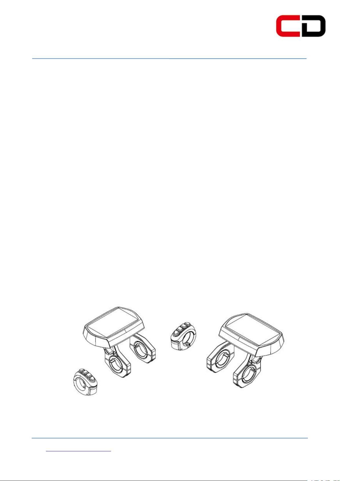
The CDC6 products use the 3.5-inch LCD screen with a light and beautiful
button, double side printed board, nylon buckle and ABS material shell. Under the
temperature ranging from -20℃ to 60℃, the shell material can ensure the good
mechanical performance of the products.
Real product
Page 5
Cloud drive intelligent technology Co.,Ltd
Page 4 of 23
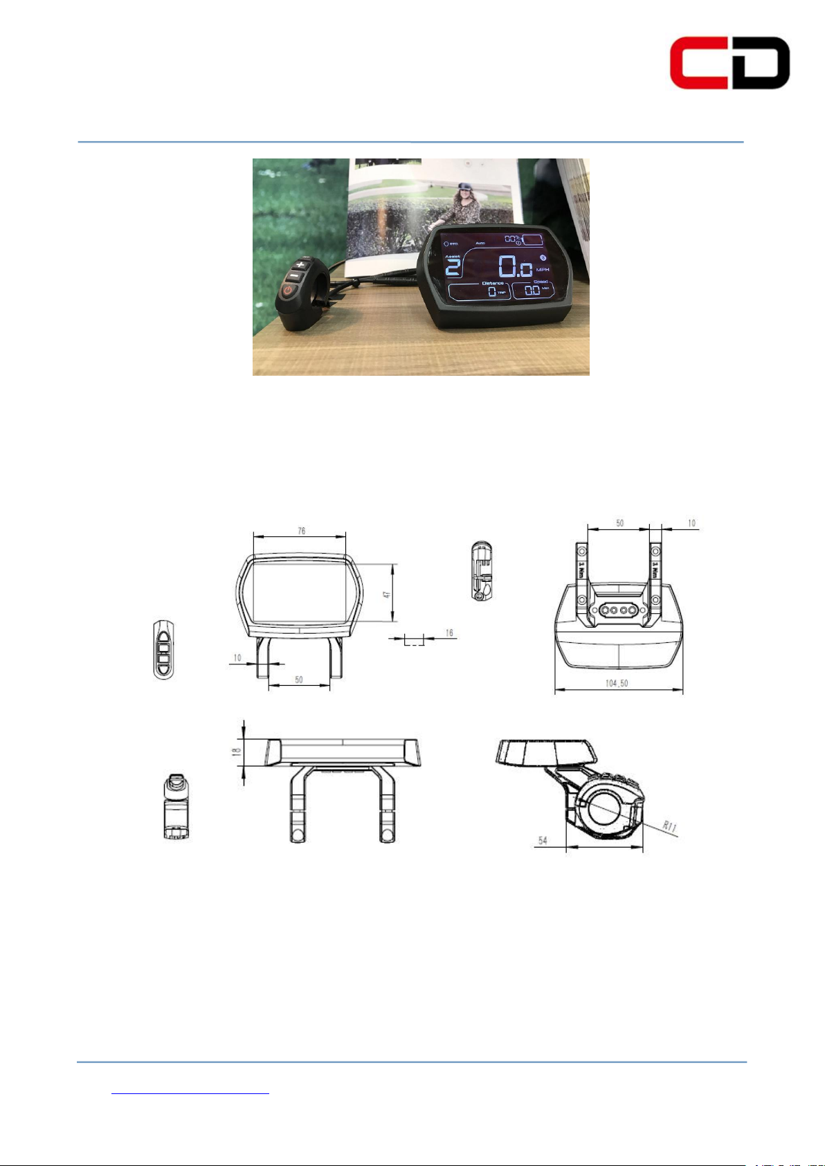
Dimension figure :( unit: mm)
Figure 2-1
Figure 2-2
Page 6

Cloud drive intelligent technology Co.,Ltd
Page 5 of 23
◆ Total distance indicator
◆ Riding distance indicator
◆ Current speed indicator
◆ Car lamp display
◆ PAS level selection
◆ Battery residual capacity indicator
◆ Error code definition
◆ Kilometers or miles
◆ Wheel diameter selection
◆ USB charging function
◆ 6Km/implementation function
3.Function summary
CDC6 is a Multifunctional display that integrated with 3.5 inch LCD. The same
display can match 24V, 36V, 48V battery. At the same time integrated with 24V, 36V
and 48V front lights. With another product CDBL_C of our company will greatly
simplify the handlebar cable. The default sleep time of the display is 10min. CDC6
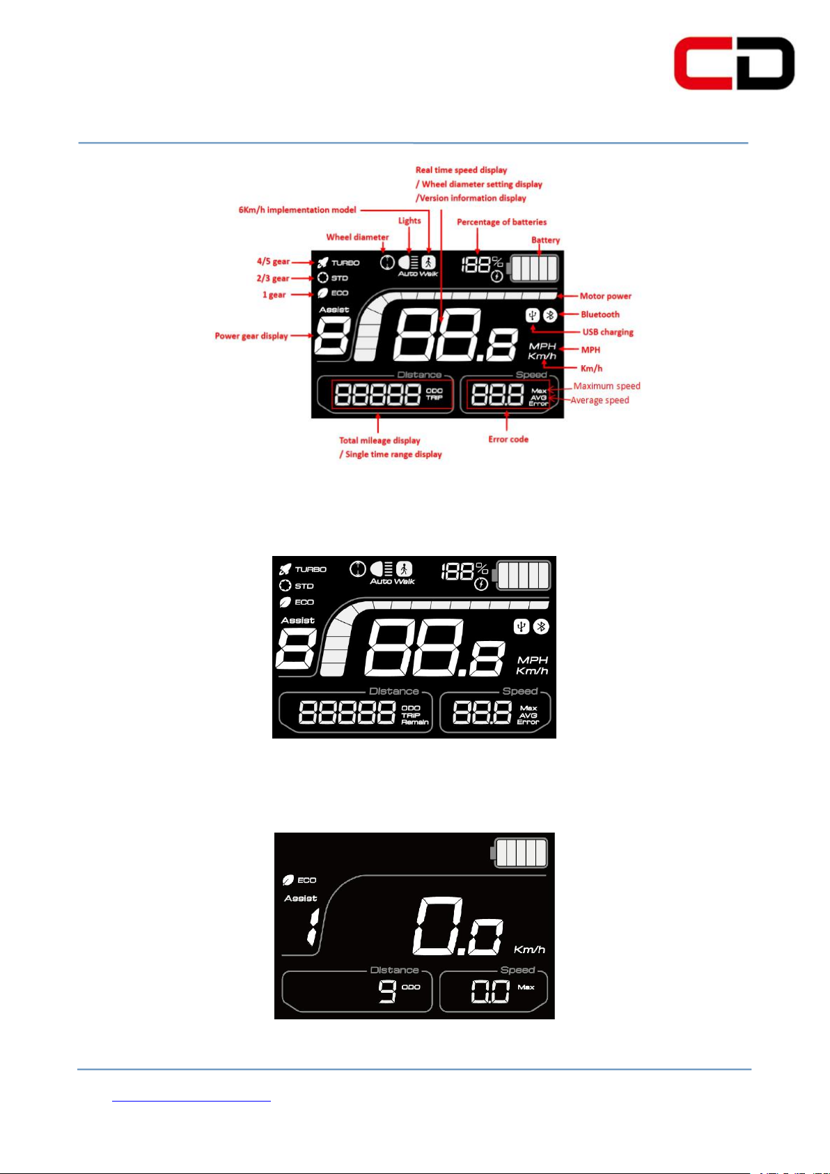
functions summary (figure 3-1)
Page 7
Cloud drive intelligent technology Co.,Ltd
Page 6 of 23
Display all(figure 3-2)
Display during use(The backlight is always bright)(figure 3-3)
Figure 3-1
Figure 3-2
Figure 3-3
Page 8
Cloud drive intelligent technology Co.,Ltd
Page 7 of 23
4.Button definition
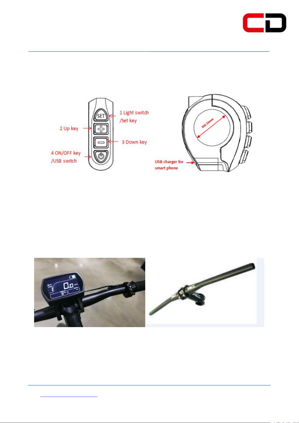
CDC6 has four buttons including SET , UP, DOWN and ON/OFF.
Figure 4
5.Installation instructions
The display will be fixed on the handlebar, and you can adjust it to the best
degree for view. Tighten the screws to finish the installation.
Insert the clasp into the vehicle tube
Page 9
Cloud drive intelligent technology Co.,Ltd
Page 8 of 23
Figure 6-1
Tighten the screws to complete the installation.
6.Normal operation
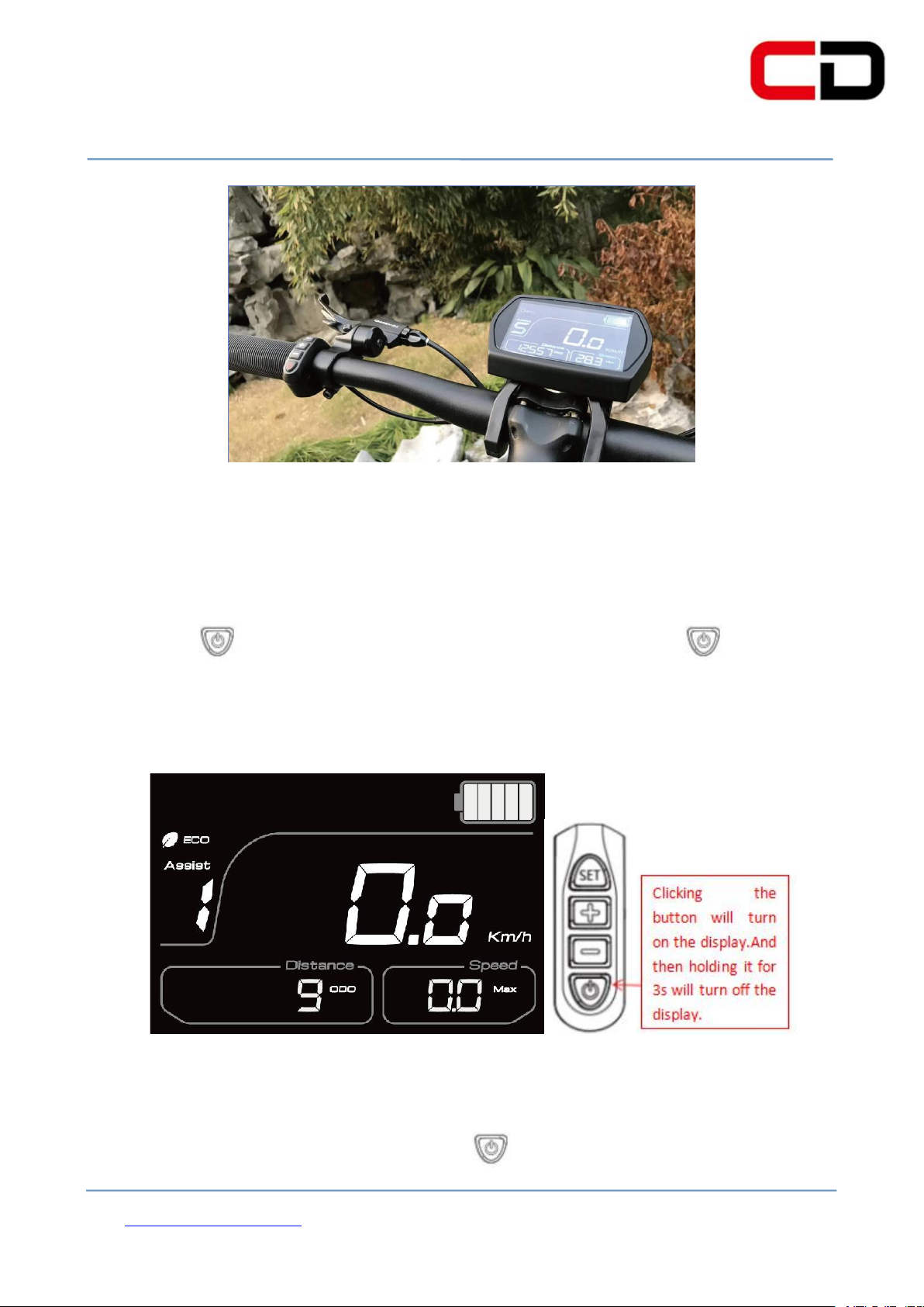
(1) Display on/off
Clicking button, the display starts to work. You can hold button for 3
seconds to turn off the display. The display is no longer cost the battery power. The
leakage current is less than 2µA. The operation process is shown in figure 6-1:
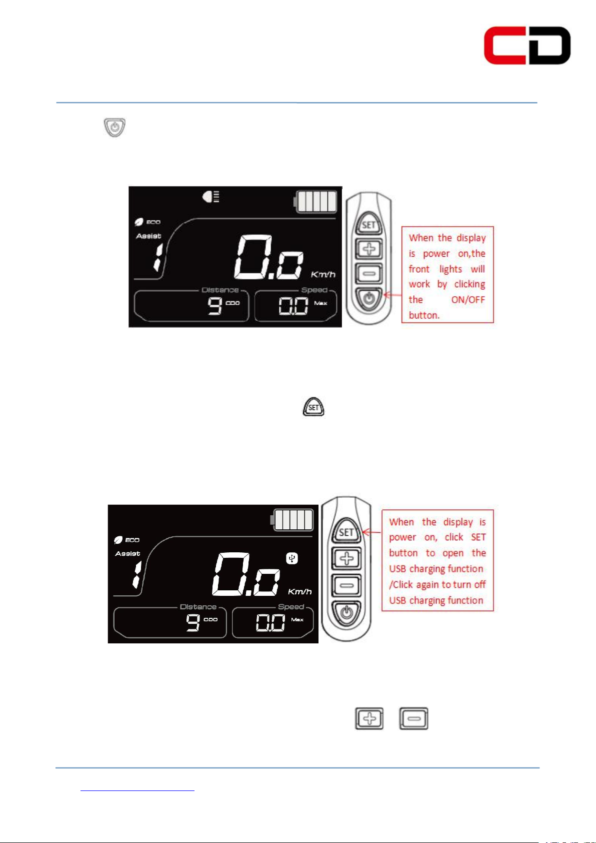
(2) Turn on/off of front lights
When the display is power on, click button to turn on the lights. Then
Page 10
Cloud drive intelligent technology Co.,Ltd
Page 9 of 23
Figure 6-2
Figure 6-3
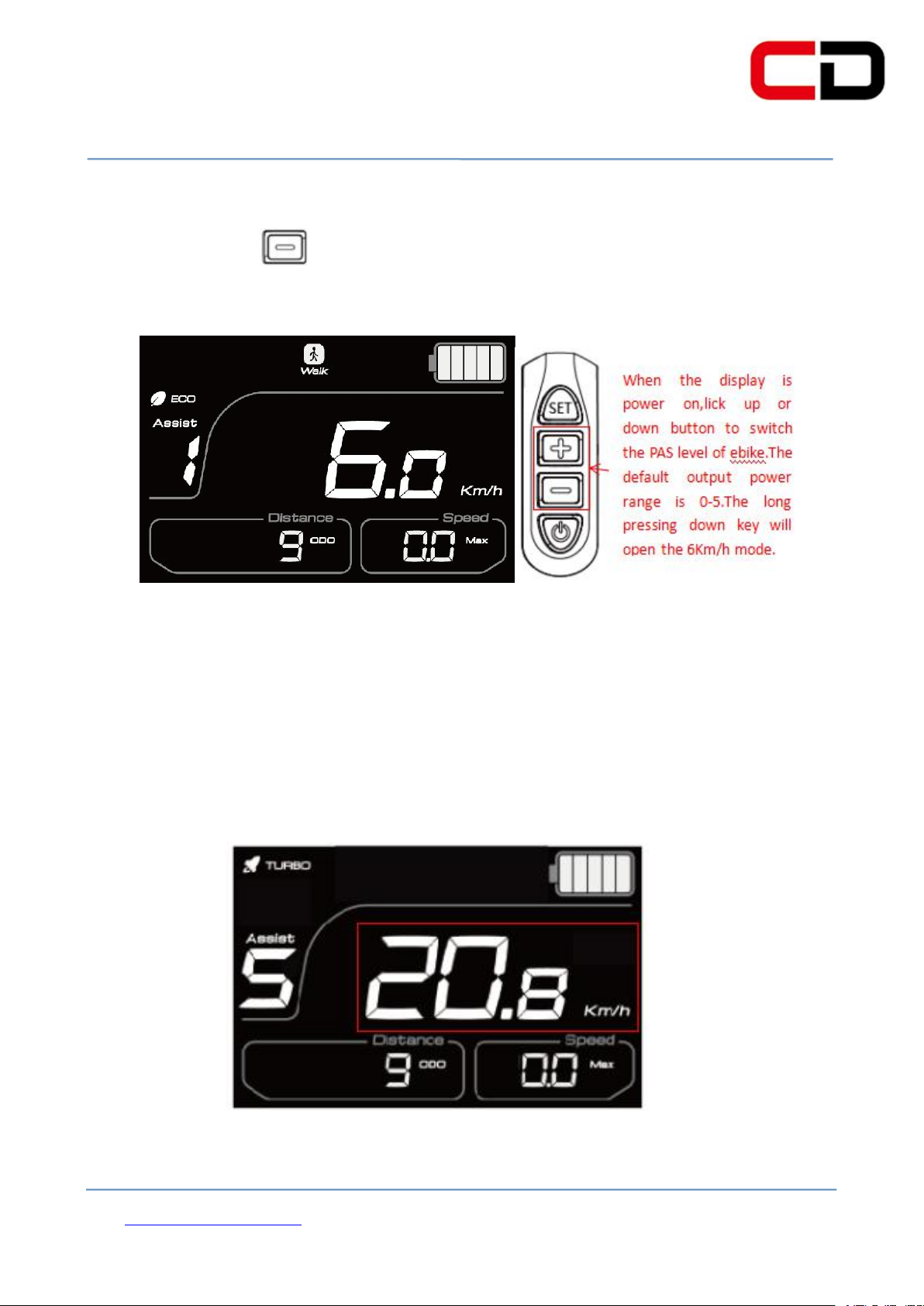
(4) PAS level selection
clicking button again, the front lights are closed. The operation process is shown
in figure 6-2: (the lights are on)
(3)Opening/closing of USB charging function
When the display is power on, click button to set up the USB charging
function. Then clicking it again, the USB charging function is closed. The operation
process is shown in figure 6-3: (The USB charging function is open)
PAS level which will
When the display is power on, you can click or button to adjust the
change the output power of the motor. The PAS level is
Page 11
Cloud drive intelligent technology Co.,Ltd
Page 10 of 23
normally set at level 1 when you power on the display, you can adjust it from 0 to 5.
The long pressing key will enter the implementation mode of 6Km/h. The
operation process is shown in figure 6-4: (6Km/h implementation mode)
Figure 6-4
(5)Display interface
Display will show: current speed, total distance, single distance, PAS level,
power, error code, motor power information and other modes.The current speed is
shown in figure 6-5.
Figure 6-5
Page 12
Cloud drive intelligent technology Co.,Ltd
Page 11 of 23
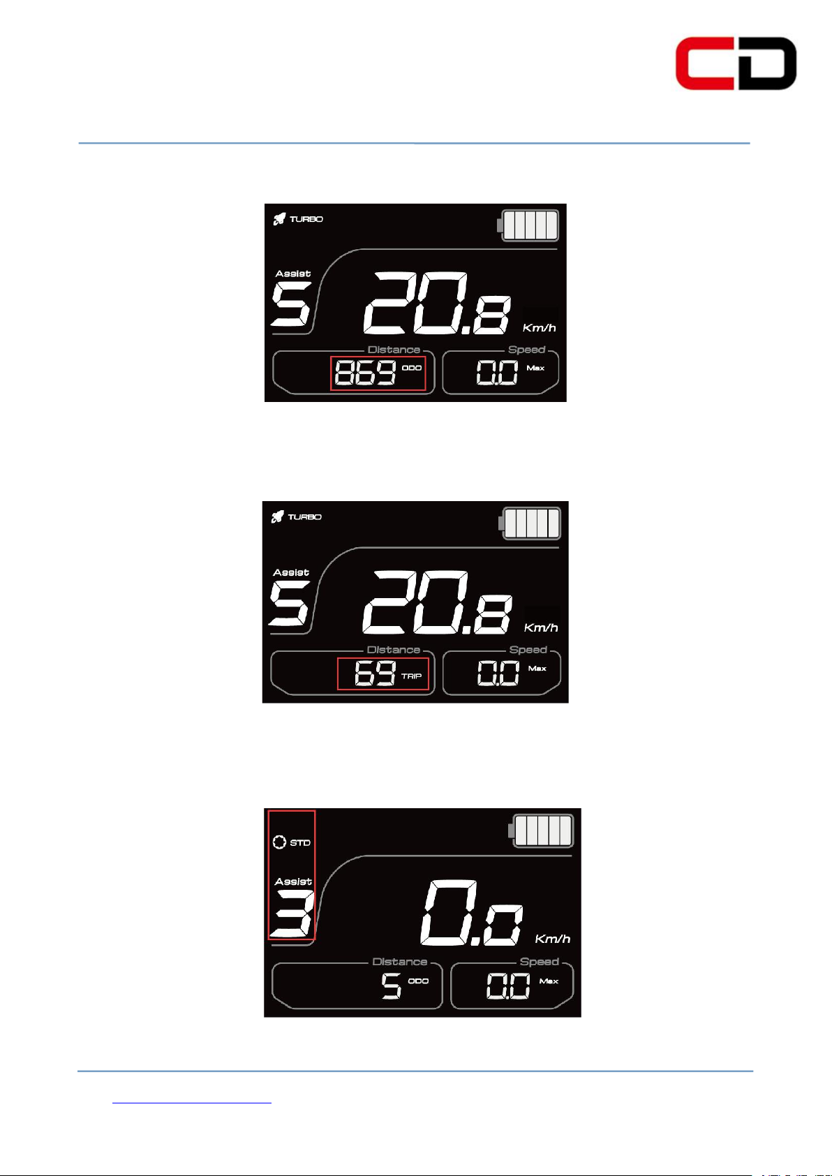
The total distance is shown in figure 6-6:
Figure 6-6
The single distance is shown in figure 6-7:
Figure 6-7
The PAS level display (level 3 in below figure) is shown in figure 6-8:
Figure 6-8
Page 13
Cloud drive intelligent technology Co.,Ltd
Page 12 of 23
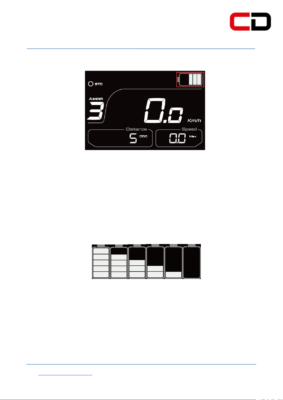
The battery power is shown in figure 6-9(the current remaining power is 3)
Figure 6-9
(6)Battery power indication
There will be five bars shown on the screen if the battery capacity is very high
enough.The less bars will show on the screen if the capacity of the battery is less.
When the battery is almost dead, the last bar will flash. You need to charge the battery
immediately. As shown in figure 6-10:
Figure 6-10
(7)Error code definition
When the ebike drive system fails, it will stop working ,and the display will show
the error code on the screen automatically. The error code will not stop showing on
the screen until the problem is solved. The reason for the error is shown in the
Page 14

Cloud drive intelligent technology Co.,Ltd
Page 13 of 23
7. General setting
attachment of error code definition table.
The display error code is shown in figure 6-11:
Figure 6-11
(8) Motor power display
The controller will feedback the motor power to the display, so that the display
can show it in real time. The riding power is shown in figure 6-12
Figure 6-12
(1)Password setting
This display’s default password is 1919. You can enter the operation interface to set
Page 15
Cloud drive intelligent technology Co.,Ltd
Page 14 of 23
other functions by entering the correct password according to the following operation
mode.
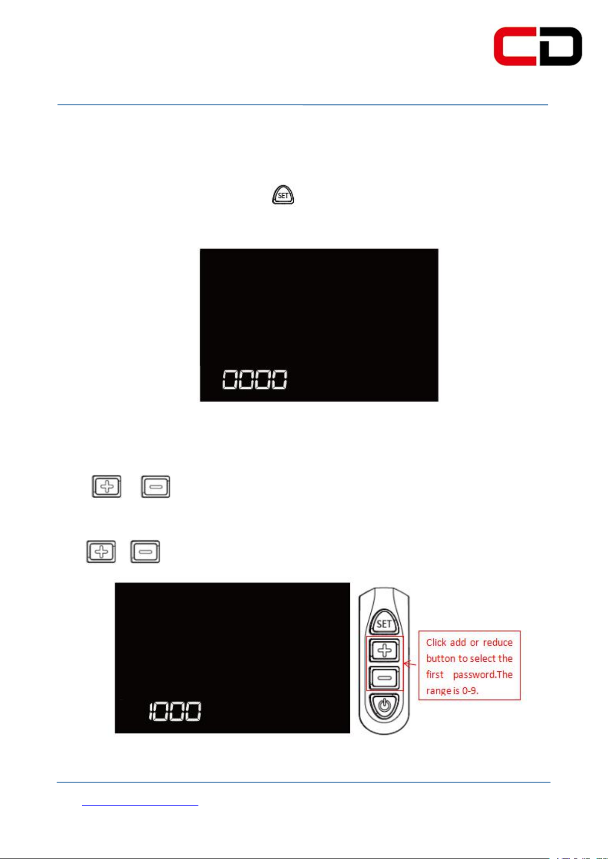
When the display is power on,hold button for 3seconds to enter the password
inputting interface, as shown in figure 7-1.
Figure 7-1
Click or button to enter the first password number setting interface, the
number will be changed from 0 to 9 or 9 to 0 step by step when you
click or button ,as shown in figure 7-2.
Figure 7-2
Page 16
Cloud drive intelligent technology Co.,Ltd
Page 15 of 23
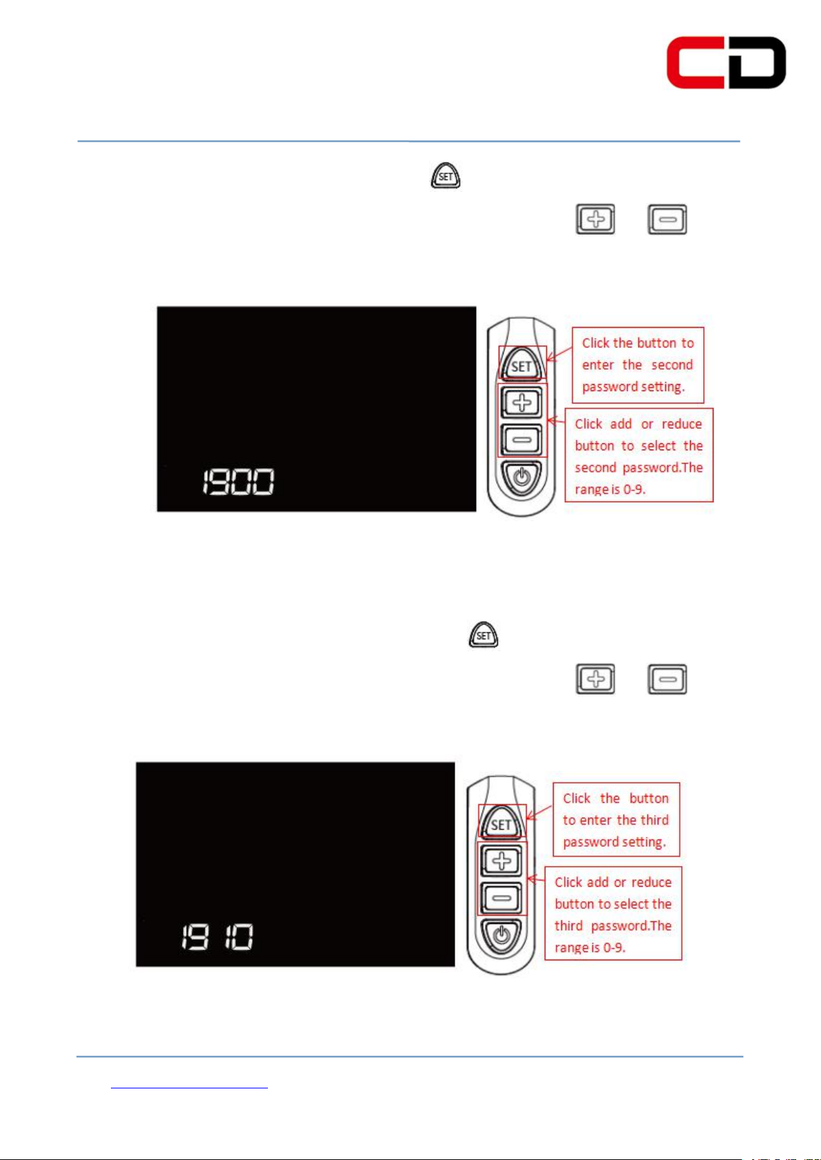
To confirm the first password number, click button, and it will enter the second
password setting interface simultaneously. Each time you click or button,
the number changes from 0-9 or 9-0 step by step, as shown in figure 7-3.
Figure 7-3
To confirm the second password number, click button, it will enter the third
password setting interface simultaneously. Each time you click or button,
the number changes from 0-9 or 9-0 step by step, as shown in figure 7-4.
Figure 7-4
Page 17
Cloud drive intelligent technology Co.,Ltd
Page 16 of 23
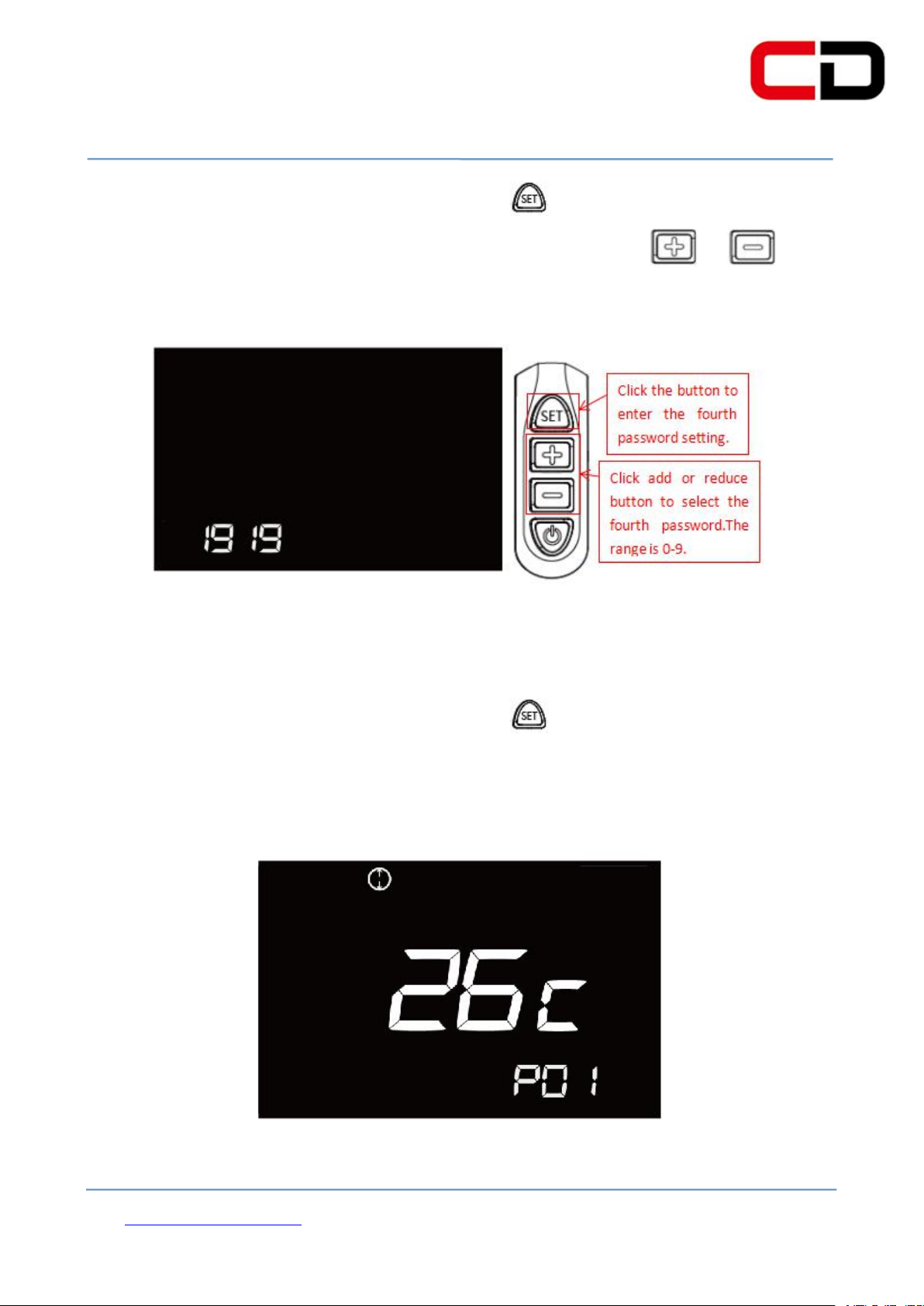
To confirm the third password number, click button, it will enter the fourth
password setting interface at the same time. Each time you click or button,
the number changes from 0-9 or 9-0 step by step, as shown in figure 7-5.
Figure 7-5
To confirm the fourth password number, click button. After you enter into the 4
correct passwords, the display will enter the wheel diameter setting interface, as
shown in the figure 7- 6.
Figure 7- 6
Page 18
Cloud drive intelligent technology Co.,Ltd
Page 17 of 23
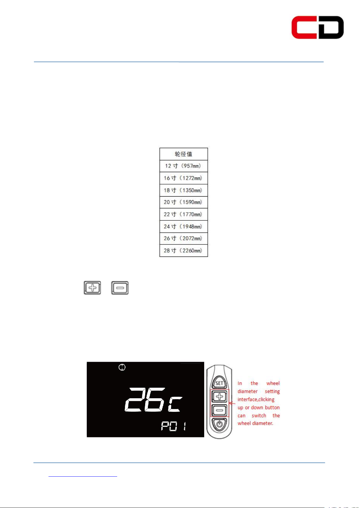
(2) Wheel diameter selection
After entering the correct password, the display will enter into the wheel diameter
setting interface, as mentioned above. The selected wheel diameter parameters, as
shown in figure7-7:
Figure 7-7
By clicking or button, you can select the corresponding wheel diameter
to ensure the accuracy of display speed and distance indication. The factory default
wheel diameter is 26C. The wheel diameter setting is shown in figure7-8: ( the wheel
diameter in the figure is 26C)
Figure 7-8
Page 19
Cloud drive intelligent technology Co.,Ltd
Page 18 of 23
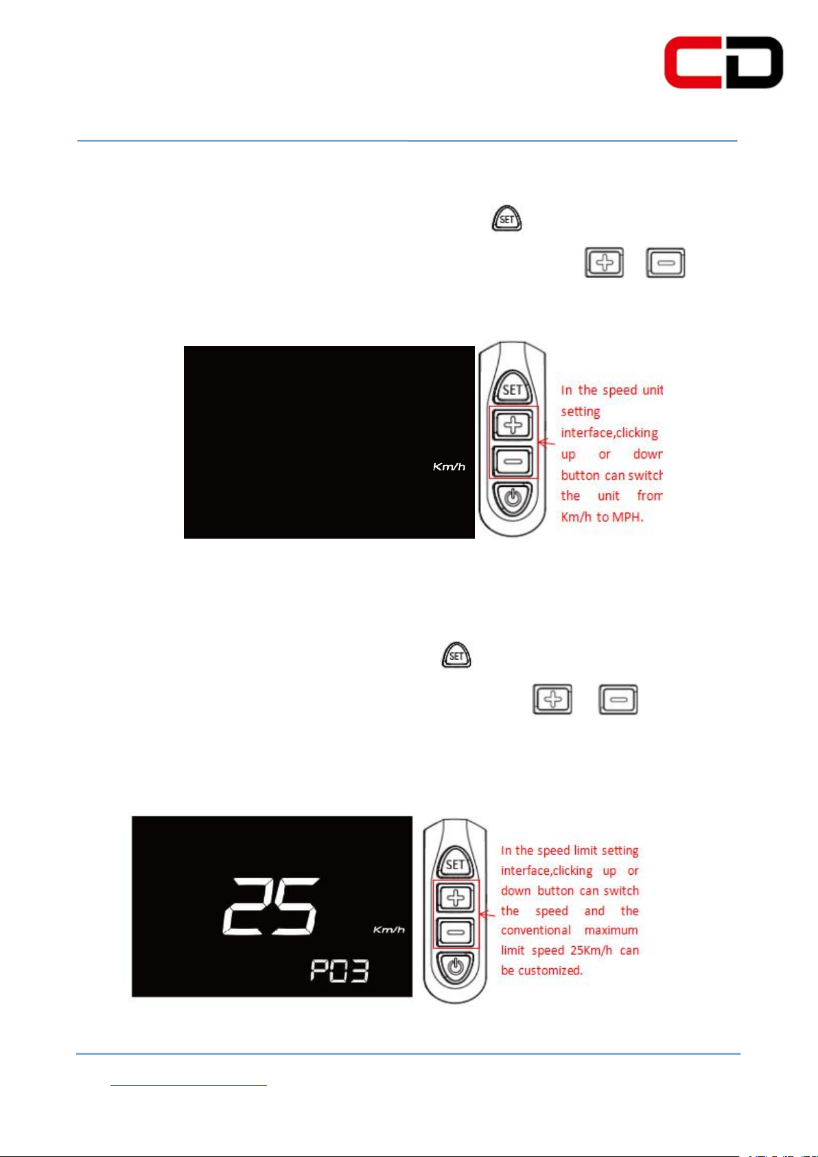
(3)Speed unit setting
After finishing the wheel diameter setting, click key to enter the speed unit
setting interface. And then, the unit will be switched by clicking or key, as
shown in figure 7-9:
Figure 7-9
(4)speed limit setting
After finishing the speed unit selection, click key to enter the speed limit setting
interface. The speed limit can be adjusted by clicking or key, and the
conventional maximum limit speed 25Km/h can be customized. The operation
process is shown in figure 7-10 (speed shown in figure is 25Km/h).
Figure 7-10
Page 20
Cloud drive intelligent technology Co.,Ltd
Page 19 of 23
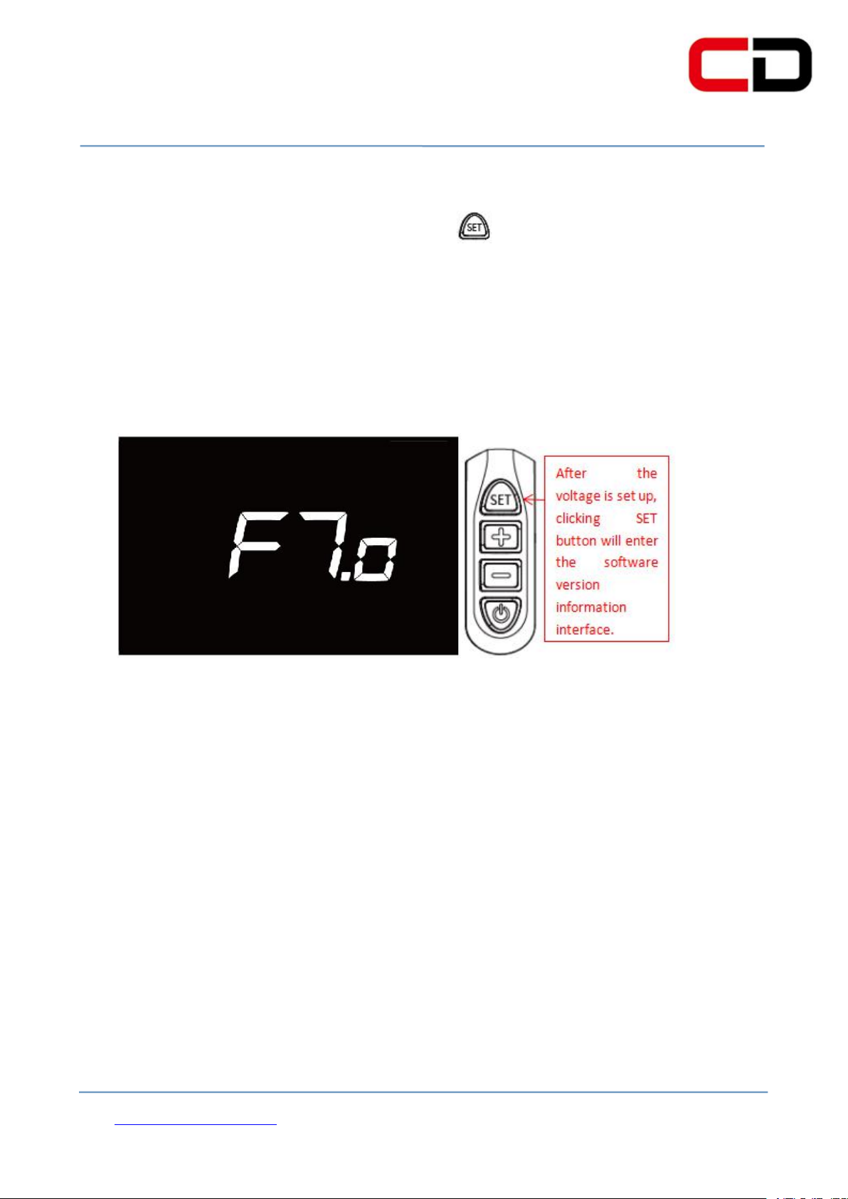
(5) Version information indication
After finishing the speed limit setting, click key, it will enter into the software
version information interface. We can better identify the system state by reading the
software version to find out the original source code to better serve you. The version
information is shown in figure 7-11 (the current version is F7.0)
Figure 7-11
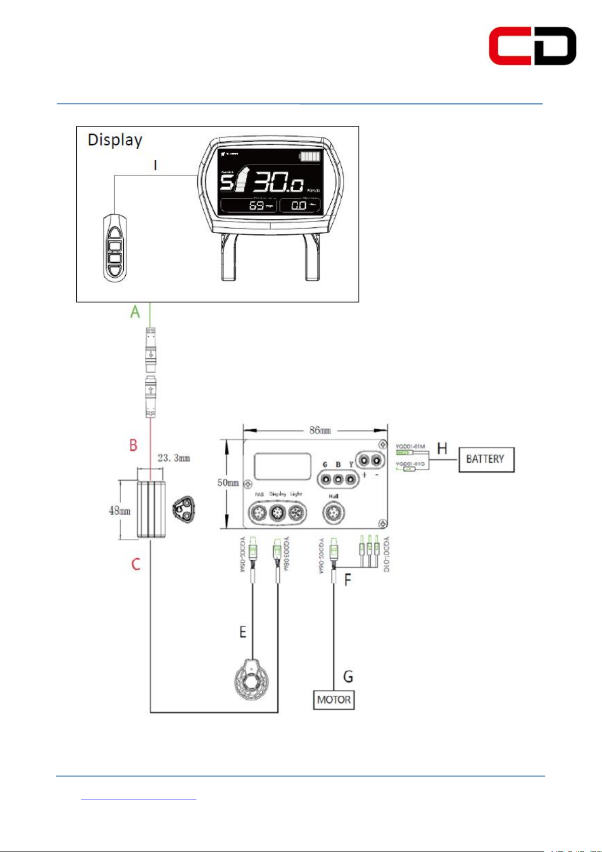
8.Cable outlet define
CDC6 is the multifunctional LCD display which has the 5 pin Cable outlet define,
the use of 24V/36V/48V battery voltage supply, followed by the power of the positive,
ground, weak lock, communications R, communications T.
Cloud drive intelligent system wiring diagram: CDC6+ CDBL_C+ CDD4+
CD_2H18. As shown in the figure 8:
Page 21
Cloud drive intelligent technology Co.,Ltd
Page 20 of 23
Figure 8
Page 22

Cloud drive intelligent technology Co.,Ltd
Page 21 of 23
(1)Disassembly or modification without authorization.
(4)Wiring scratch or breakage.
9.Q&A
Q:Why the display is not able to start up?
A:Check the connector that between display and controller.
Q:How to deal with the error code?
A:Fix it to the maintenance place immediately. If it cannot be resolved, you
can go to the electric vehicle repair points repair it in a timely manner.
10.Quality assurance and warranty scope
Warranty
( 1 ) Under warranty, our company will shoulder the responsibility to provide
limited warranty to any faults caused by the quality of the product under normal
use.
(2)The warranty period lasts for 18 months since the date of purchase.
Other items
The following items does not belong to warranty scope
(2 ) Malfunction or damage caused by the misuse or improper installation and
debugging by the users or the third party.
(3)Shell scratch or breakage after leaving the factory.
(5)Malfunction or damage caused by the force majored (fire, earthquake etc. ) or
Page 23

Cloud drive intelligent technology Co.,Ltd
Page 22 of 23
There will be error code showed on the display while the system doesn’t work.
1. Error code0x01: Then display is in normal condition.
2. Error code0x03: The ebike is braking.
3. Error code0x04: The throttle is no homing (staying in the hing position).
4. Error code0x05: Throttle is broken.
5. Error code0x06: Battery is under voltage protection.
6. Error code0x07: Overvoltage protection.
7. Error code0x08: Motor Holzer signal line is broken
8. Error code0x09: Motor phase is broken.
9. Error code0x10: The controller temperature is high enough to reach the
protection point.
10. Error code0x11: The motor temperature is high enough to reach the
protection point.
11. Error code0x12: Current sensor is broken.
12. Error code0x13: Battery temperature is broken.
13. Error code0x14: Temperature sensor in motor is broken.
14. Error code0x15: Temperature sensor in controller is broken.
15. Error code0x21: PAS is broken.
natural disasters (lightening etc.)
(6)Beyond Warranty period.
Error code definition table
Page 24

Cloud drive intelligent technology Co.,Ltd
Page 23 of 23
16. Error code0x22: BMS communication is failure.
17. Error code0x23: The front light is broken.
18. Error code0x24: The front light is failure.
19. Error code0x25: Torque signal of torque sensor is failure.
20. Error code0x26: Speed signal of torque sensor is failure.
21. Error code0x30: Communication is failure.
The error code explanation is based on the correct system from
Cloud drive intelligent technology Co., Ltd
 Loading...