

Page 1
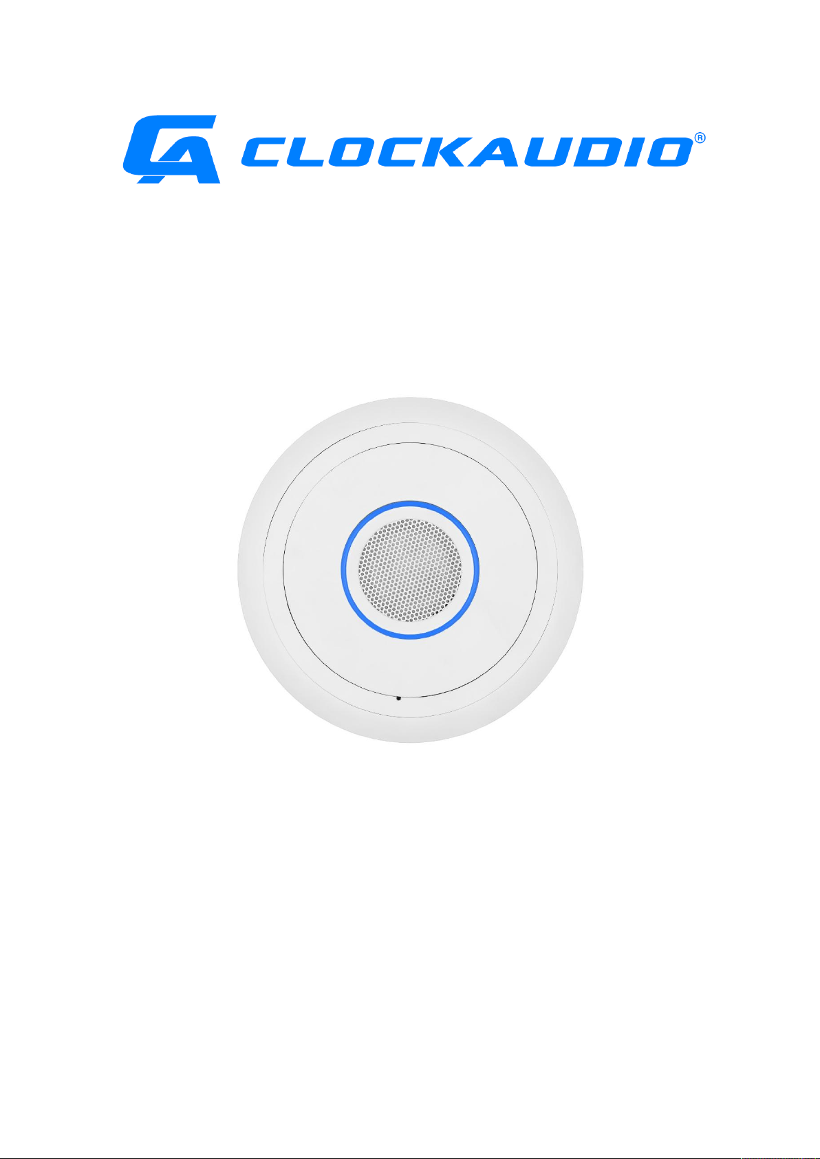
User Guide
TIM-1000
(Tracking Intelligent Microphone)
Page 2

Page 3

Thank you for purchasing a Clockaudio product. We are confident that this product will give
you many years of trouble free operation.
As part of Clockaudio’s continual ongoing programme of product development,
improvements to the existing TIM-1000 microphone range may be made to further increase
the already excellent reliability and functionality.
Note: Where necessary, instructions are also provided in Canadian French.
Copyright
© Copyright 2019 Clockaudio Ltd. All rights reserved.
Audinate®, the Audinate logo and Dante® are registered trademarks of Audinate Pty Ltd.
Disclaimer
This User Guide is written for users of the TIM-1000 Intelligent Tracking Microphone, to assist in
installation and operation. It is not intended to be a detailed source of information.
No part of this document may be reproduced in any form without the written permission of the
copyright owner.
The contents of this document are subject to revision without notice due to continued progress in
methodology, design and manufacturing. Clockaudio shall have no liability for any error or damage
of any kind resulting from the use of this document.
V1.2 2019-06
Page i of vi
Page 4

Page ii of vi
V1.2 2019-06
Page 5

READ ME FIRST – SAFETY INSTRUCTIONS
Please ensure that the following safety instructions are followed. If the product is reissued to another
party, please ensure that this document is provided.
1. Ensure that all warnings and important notes are adhered to;
2. Follow all instructions carefully;
3. If the unit needs to be cleaned, only use dry cloth; the unit is not waterproof;
4. There may be a risk of fire if the unit is exposed to dripping or running water or other liquids;
5. Do not install in a totally confined area where there is no air movement over the back of the unit;
6. Do not install the product near heat sources such as radiators, stoves, etc…;
7. Only use the attachments supplied, specified or recommended by Clockaudio.
Assurez-vous que les instructions de sécurité suivantes sont suivies. Si le produit est réédité
à une autre partie, assurez-vous que ce document est fourni.
1. Assurez-vous que toutes les mises en garde et notes importantes sont respectées.
2. Suivez toutes les instructions attentivement.
3. Si l’unité doit être nettoyée, utilisez uniquement un chiffon sec. L’appareil n’est pas
étanche.
4. Il peut y avoir un risque d’incendie si l’appareil est exposé à des gouttes d’eau, à de l’eau
courante ou à tout autre liquide.
5. N’installez pas le produit dans une zone totalement confinée où l’air ne circule pas à
l’arrière de l’appareil.
6. N’installez pas le produit à proximité de sources de chaleur telles que radiateurs,
cuisinières, etc.
7. Utilisez uniquement les pièces jointes fournies, spécifiées ou recommandées par
Clockaudio.
V1.2 2019-06
Page iii of vi
Page 6

Warning!
Do not remove the covers as there is sensitive equipment inside. Only Clockaudio Ltd or its approved
service engineers are permitted to service this equipment. There are no user serviceable parts inside.
Attention!
Ne retirez pas les couvercles, car il y a du matériel sensible à l’intérieur. Seul Clockaudio Ltée
ou ses techniciens agréés sont autorisés à entretenir cet équipement. Le produit ne contient
aucune pièce réparable par l’utilisateur.
Caution!
Unauthorised maintenance, repair or the use of non-approved replacements may affect the
equipment specification and invalidate any warranties.
Mise en garde!
Un entretien non autorisé, des réparations ou l’utilisation de pièces de rechange non
approuvées peuvent affecter les spécifications de l’équipement et invalider les garanties.
Equipment covered by this User Guide.
This User Guide covers the TIM-1000 Intelligent Tracking Microphone. The product is specifically
designed for use in board rooms, huddle rooms or other enclosed meeting room spaces.
Page iv of vi
V1.2 2019-06
Page 7

Contents
1 Overview ......................................................................................................................................... 1
2 Package Contents ............................................................................................................................ 2
2.1 Contents of the TIM-1000-CM (Ceiling Mount version) ......................................................... 2
2.2 Contents of TIM-1000-PM (Pole Mount version) ................................................................... 3
3 Installation ...................................................................................................................................... 4
3.1 Ceiling tile mount installation ................................................................................................. 4
3.2 Pole mount installation ........................................................................................................... 6
3.3 Connecting to TIM-1000 ......................................................................................................... 9
3.4 Adding additional units ........................................................................................................... 9
3.5 Coverage Area ......................................................................................................................... 9
3.6 Uninstallation of TIM-1000 ................................................................................................... 10
3.6.1 Uninstallation of TIM-1000 Ceiling Mount ................................................................... 10
3.6.2 Uninstallation of TIM-1000 Pole Mount ....................................................................... 11
3.7 TIM-1000 Power up sequence .............................................................................................. 12
4 Feature Description....................................................................................................................... 13
5 Understanding the GUI and Features ........................................................................................... 14
5.1 Passwords ............................................................................................................................. 14
5.2 Home Tab .............................................................................................................................. 15
5.2.1 Tracking ......................................................................................................................... 15
5.2.2 Noise Suppression ......................................................................................................... 15
5.2.3 APT (Adaptive Proximity Tracking) ................................................................................ 15
5.2.4 Light Ring ....................................................................................................................... 16
5.2.5 EQ settings .................................................................................................................... 17
5.3 Advanced Tab ........................................................................................................................ 17
5.3.1 Device setup .................................................................................................................. 17
5.3.2 Control network IP settings .......................................................................................... 17
5.3.3 Dante Settings ............................................................................................................... 17
5.3.4 Time settings ................................................................................................................. 17
5.3.5 Software upgrade .......................................................................................................... 18
5.3.6 Advanced controls ........................................................................................................ 18
5.4 Password Reset via GUI......................................................................................................... 19
6 TIM-1000 Physical connections .................................................................................................... 20
6.1 RJ45 Port Connections .......................................................................................................... 20
6.2 Factory Defaults Reset Switch............................................................................................... 20
7 Configuring TIM-1000 ................................................................................................................... 21
7.1 Additional TIM-1000 configuration ....................................................................................... 22
7.2 Configuring TIM-1000 on Dante networks ........................................................................... 22
8 Troubleshooting ............................................................................................................................ 23
V1.2 2019-06
Page v of vi
Page 8

9 Factory Configuration ................................................................................................................... 24
10 Specifications ................................................................................................................................ 25
11 Programming using UDP commands ............................................................................................ 26
11.1 ID (Identify Unit) ................................................................................................................... 27
11.2 FU (Find Unit) ........................................................................................................................ 27
11.3 VERSION (Version) ................................................................................................................ 28
11.4 DEFAULTS (Defaults) ............................................................................................................. 28
11.5 STS (Set TS State) .................................................................................................................. 29
11.6 GTS (Get TS Status) ............................................................................................................... 29
11.7 STSB (Set TS Brightness) ........................................................................................................ 30
11.8 GTSB (Get TS Brightness) ...................................................................................................... 30
11.9 SRGB (Set RGB State) ............................................................................................................ 31
11.10 GRGB (Get RGB State) ........................................................................................................... 31
11.11 APT (Set APT) ........................................................................................................................ 32
11.12 TRACKING (Tracking Mode) .................................................................................................. 32
11.13 EQ (EQ Settings) .................................................................................................................... 33
11.14 NOISESUP (Noise Suppression) ............................................................................................. 33
12 Product Warranty ......................................................................................................................... 34
13 Product Disposal ........................................................................................................................... 35
Page vi of vi
V1.2 2019-06
Page 9

1 Overview
The Tracking Intelligent Microphone (TIM) breaks the mould for ceiling microphones. Designed for
use in AV conference and huddle room applications, TIM-1000 provides unparalleled performance.
With automatic tracking of participants within the meeting room, TIM-1000 unshackles them to
freely move around the room. Introducing the unique Adaptive Proximity Tracking (APT) technology,
and noise suppression, TIM-1000 captures and delivers the best possible sound. With seamless
integration into DANTE network and integration with other third party controllers, makes TIM-1000
an ideal choice for any conferencing applications.
Designed from the ground up and integrating seamlessly with Dante and AES67 networks, third party
controllers, TIM-1000 offers a host of unique features that allows deployment flexibility and
configurability using an intuitive GUI.
Major functionality introduced within TIM-1000 includes:
Tracks meeting participants within the room
APT technology for best possible sound output
Eliminates unwanted steady state noise e.g. air conditioning, projectors
User selectable colours for the LED ring
Built-in equalizer
Supports DANTE and AES 67
GUI through standard Web browser
Powered over Ethernet (PoE)
Separate control and data paths for added security
API commands via UDP
Easy setup and install
Available in 2 formats, TIM-1000 is suitable for all conference/huddle room applications:
TIM-1000-CM (Ceiling mount)
TIM-1000-PM (Pole mount)
Note: Neither TIM-1000-CM or TIM-1000-PM are suitable for installations in Plenum spaces.
V1.2 2019-06
Page 1 of 35
Page 10
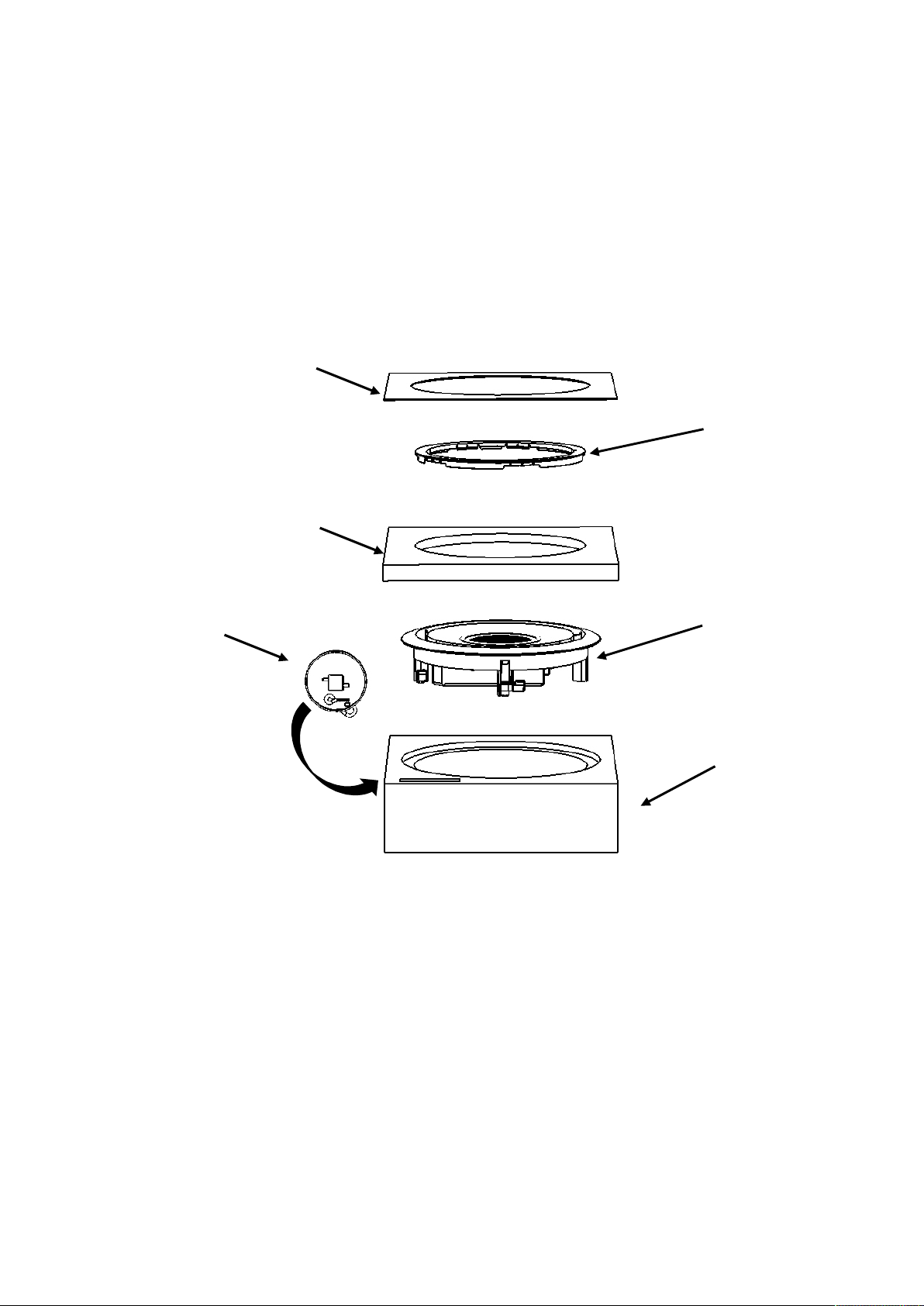
2 Package Contents
TIM-1000 cable
TIM-1000 top
TIM-1000 trim ring
TIM-1000 bottom
Contents of Carton
TIM-1000 template
2.1 Contents of the TIM-1000-CM (Ceiling Mount version)
The Ceiling Mount version of TIM-1000 comes in a single carton. This user guide and cardboard
template for cutting hole in ceiling (not shown below) are also located in this carton.
for ceiling hole
packaging foam cover
safety harness
TIM-1000 product
packaging foam
cover
Page 2 of 35
V1.2 2019-06
Page 11
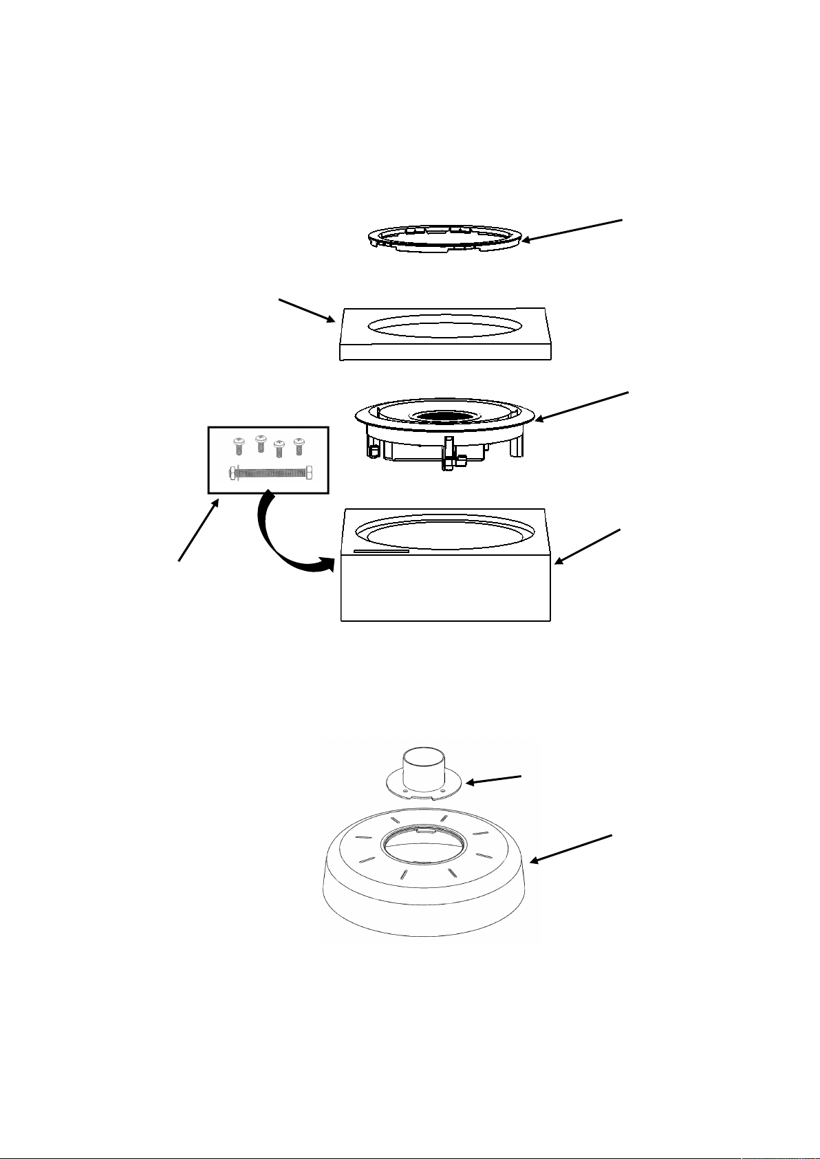
2.2 Contents of TIM-1000-PM (Pole Mount version)
TIM-1000 metal bracket
TIM-1000 top
TIM-1000 trim ring
TIM-1000 product
TIM-1000 bottom
cover
Contents of Carton #2
TIM-1000 top cover
Bag containing
Contents of Carton #1
The Pole Mount version of TIM-1000 comes in two cartons. This user guide is located in Carton #1.
packaging foam cover
packaging foam
1x M6x65 bolt
1 x M6 nut
1 x M6 washer
4 x M4x10 screws
V1.2 2019-06
Page 3 of 35
Page 12

3 Installation
1.
2.
3.
4.
port
Tile
There are two versions of TIM-1000: a ceiling microphone that’s installed in the false ceiling or a pole
mount version that is hung down vertically from the ceiling. In either case, the distance from the
microphone front face to the ground shall be no more than 2.45m or 8 feet. TIM-1000 is easy to
install using the guide below. Pickup area of the product is 9.1m or 30ft diameter.
3.1 Ceiling tile mount installation
Place the provided template on the ceiling tile
where needed, draw the hole and then cut
appropriately.
Placez le gabarit fourni sur la dalle de
plafond si nécessaire, faites un trou puis
coupez de manière appropriée.
Insert an M4 eyebolt into one of the standoffs
on the back of TIM-1000.
Insérez un boulon à œil M4 dans l’une des
entretoises à l’arrière du TIM-1000.
Template
Attach the cable safety harnesses to a joist or a
fixed structure in the ceiling.
Attachez les câbles de sécurité à une solive
ou à une structure fixe au plafond.
Connect the shielded RJ45 Cat5 cables to TIM1000; Dante cable has to be connected to PoE;
control cable (does not need to be PoE)
connects to CTRL1.
Connectez les câbles RJ45 Cat5 blindés au
TIM-1000. Le câble Dante doit être
connecté au PoE; le câble de contrôle (qui
n’a pas besoin d’être PoE) se connecte à
CTRL1.
PoE port
Control
Page 4 of 35
V1.2 2019-06
Page 13
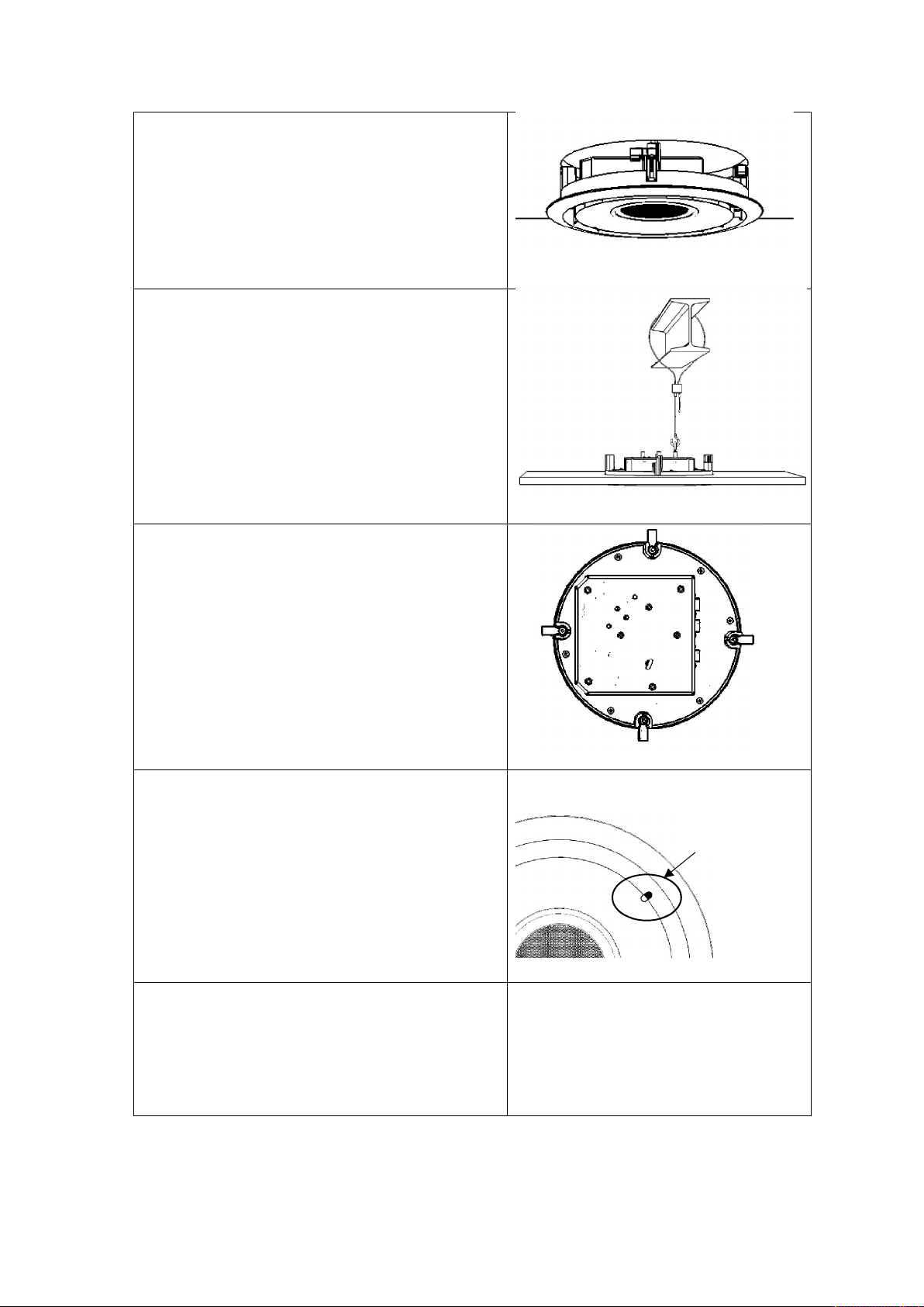
5.
Guide the frame through the hole in the ceiling
6.
7.
8.
9.
tile ensuring that the fixing clips are pointing
inwards.
Faites passer le TIM-1000 à travers le trou
de la dalle de plafond en veillant à ce que
les pinces de fixation soient dirigées vers
l’intérieur.
Attach the hook of the safety harness through
the M4 eyelet and pull the cable of the safety
harnesses to take up any necessary slack.
Fixez le crochet du câble de sécurité à travers
les œillets M4 et tirez sur le câble de sécurité
afin qu’il n’y ait plus de jeu.
Screw the four screws into the ceiling cover.
This rotates the fixing clips and clamps
TIM-1000 to the ceiling.
Vissez les quatre vis dans le couvercle du
plafond. Ceci fait pivoter les pinces de
fixation de TIM-1000 au plafond.
Align the pip on TIM-1000’s front face with the
hole in the trim ring and clip it in gently.
Alignez le picot de la face avant du TIM1000 avec la bague de finition et attachezle doucement.
Connect the free ends of the shielded RJ45 Cat
5 cables to the appropriate network switches.
Connectez les extrémités libres des câbles
blindés RJ45 Cat 5 aux commutateurs de
réseau appropriés.
V1.2 2019-06
Align trim ring
hole with “pip”
on main body
Page 5 of 35
Page 14
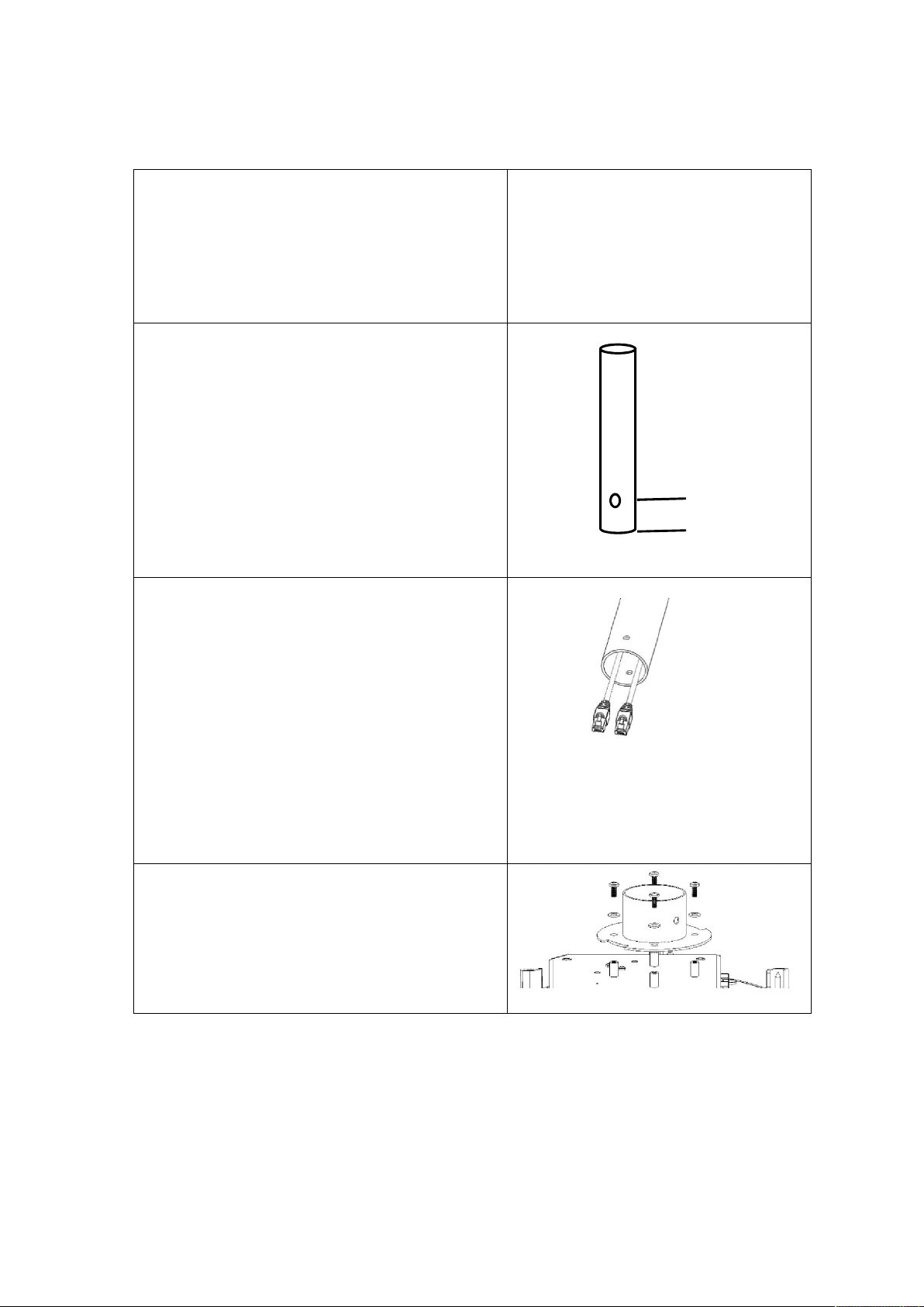
3.2 Pole mount installation
1.
2.
3.
4.
20mm
Connect either a 50mm or 2” diameter pole to
the ceiling or an overhead fixture via suitable
means.
Connectez un poteau de 50 mm ou de 2 po
de diamètre au plafond ou à un plafonnier
par des moyens appropriés.
Drill a 6.5mm diameter hole (M6) that is 20mm
from the bottom end of the pole.
Percez un trou de 6,5 mm de diamètre
(M6) à 20 mm de l’extrémité inférieure du
poteau.
Feed the Shielded RJ45 Cat5e cables through
the pole so that the RJ45 connectors appear
through the bottom end; Dante cable has to be
connected to PoE; control cable (does not need
to be PoE) connects to CTRL1.
Faites passer les câbles RJ45 Cat5e blindés
à travers le poteau de sorte que les
connecteurs RJ45 apparaissent à travers
l’extrémité inférieure. Le câble Dante doit
être connecté au PoE. Le câble de contrôle
(qui n’a pas besoin d’être PoE) se connecte
à CTRL1.
Connect the metal bracket to TIM-1000’s body
using 4 x M4 screws (supplied).
Reliez le support en métal au corps du TIM1000 à l’aide de quatre vis M4 (fournies).
Page 6 of 35
V1.2 2019-06
Page 15
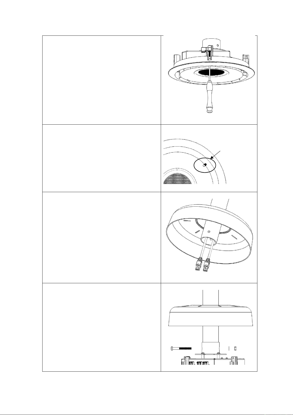
5.
Unscrew the four ceiling mount fixing clips as
6.
7.
8.
on main body
these are not required.
Dévissez les quatre pinces de fixation du
support de plafond, car elles ne sont pas
nécessaires.
Align the pip on TIM-1000’s front face with the
hole in the trim ring and clip it in gently.
Alignez le picot de la face avant du TIM1000 avec la bague de finition et attachezle doucement.
Align trim ring
hole with “pip”
Feed TIM-1000’s top cover through the pole
connected to the ceiling.
Faites passer le couvercle supérieur du
TIM-1000 à travers le poteau connecté au
plafond.
Feed the ceiling pole into the metal bracket
and lock with attached bolt, washer and nut.
Introduisez le poteau de plafond dans le
support en métal et verrouillez-le avec le
boulon, la rondelle et l’écrou fixés.
V1.2 2019-06
Page 7 of 35
Page 16
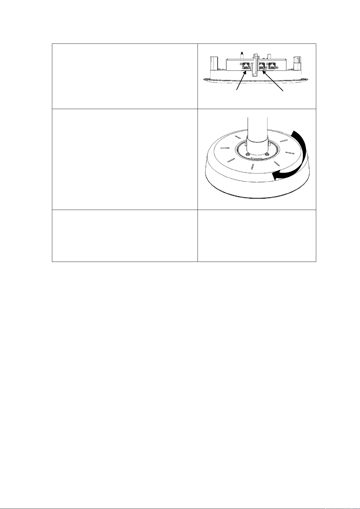
9.
Connect the free ends of the shielded RJ45 Cat
10.
11.
port
5 cables to the appropriate network switches.
Connectez les extrémités libres des câbles
blindés RJ45 Cat 5 aux commutateurs de
réseau appropriés.
Position the top cover onto TIM-1000, ensuring
it’s correctly positioned, and rotate clockwise
to lock in place.
PoE port
Control
Placez le couvercle supérieur sur le TIM1000 en vous assurant qu’il est
correctement positionné et faites-le
pivoter dans le sens des aiguilles d’une
montre pour le verrouiller en place.
Connect the other end of the shielded Cat5e
cable to the appropriate network switches.
Connectez l’autre extrémité du câble
blindé Cat5e aux commutateurs de réseau
appropriés.
Once the units have been connected and TIM-1000 has performed its self-test, it’s ready to be
configured.
By default, when the units are shipped, they are configured for DHCP for the Control and Dante
networks. Therefore, once units are powered up, a DHCP server shall be available to provide
TIM-1000 with a control and data ports’ IP addresses. If no DHCP server is available, the data port
will obtain its IP address using link local (i.e. in the address range of 169.254.xxx.xxx).
Page 8 of 35
V1.2 2019-06
Page 17

3.3 Connecting to TIM-1000
To display TIM-1000’s web GUI, locate its Control port’s IP address and using a web browser connect
to it
http::/<Control IP address>/index.php
Default password for both Home and Advanced pages is “clockaudio”.
3.4 Adding additional units
For some room configurations, it may be desirable to have more than one TIM-1000. For this
scenario, it is possible to add other unit(s) to the room. There are two ways to cable these additional
units.
1. Daisy-chain control path – For this option, from the first unit’s Control port 2 (CTRL 2) attach
a shielded Cat 5e cable to the control port (CTRL 1) on the second unit. If multiple units need
to be connected to cover a large area, then repeat the process of connecting CTRL 2 to the
next unit’s CTRL 1.
It is important to note that the PoE or Data Port cannot be daisy chained.
2. Run separate cables – As per the first unit, separate cables for Data and Control can be run.
3.5 Coverage Area
These figures are typical and the coverage area will vary depending upon the install.
Typical height from floor level to TIM-1000 is 8ft or 2.44m.
Typical coverage area for TIM-1000 at this height will be 30ft by 30ft or 9.14m x 9.14m.
Setting APT function to other than OFF can simulate a larger pickup area as the quieter sounds will
be uplifted.
V1.2 2019-06
Page 9 of 35
Page 18
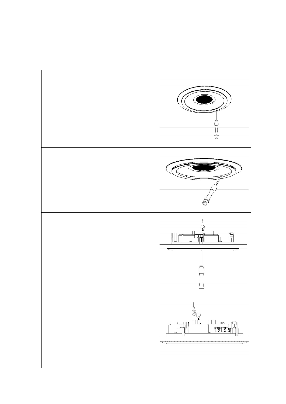
3.6 Uninstallation of TIM-1000
1.
2.
3.
4.
In the event that TIM-1000 needs to be removed, please follow the following process.
3.6.1 Uninstallation of TIM-1000 Ceiling Mount
Insert a small flat-blade screw driver or a small
allen key into the hole.
Insérez un petit tournevis plat ou une
petite clé Allen dans le trou.
Gently prise out the Trim ring out taking extra
care where the ring is clipped in tight.
Soulevez délicatement la bague de finition
en faisant très attention lorsque la bague
est serrée.
Undo the four screws until you feel that the
“dog-leg” clips are turning about 90 degrees.
Dévissez les quatre vis jusqu’à ce que vous
sentiez que les pinces patte de chien (dog-
leg) tournent à environ 90 degrés.
Release the cable harness from the back of the
unit.
Détachez le harnais de câble à l’arrière de
l’appareil.
Page 10 of 35
V1.2 2019-06
Page 19
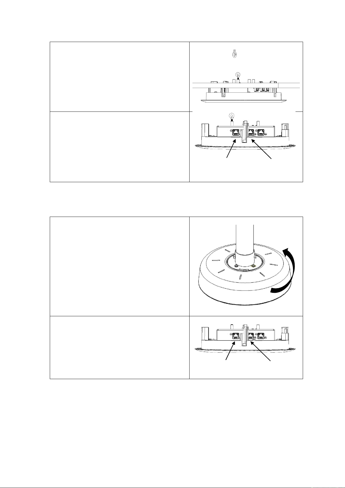
5.
Gently pull out TIM-1000 from the ceiling tile.
6.
1.
2.
port
port
Retirez doucement le TIM-1000 de la dalle
de plafond.
Remove the PoE and Control cable(s).
Retirez les câbles PoE et de contrôle.
3.6.2 Uninstallation of TIM-1000 Pole Mount
Rotate the TIM-1000’s top cover anti-clockwise
and lift up.
Faites pivoter le couvercle supérieur du
TIM-1000 dans le sens inverse des aiguilles
d’une montre et soulevez-le.
PoE port
Control
Remove the PoE and Control cable(s).
Retirez les câbles PoE et de contrôle.
V1.2 2019-06
PoE port
Control
Page 11 of 35
Page 20
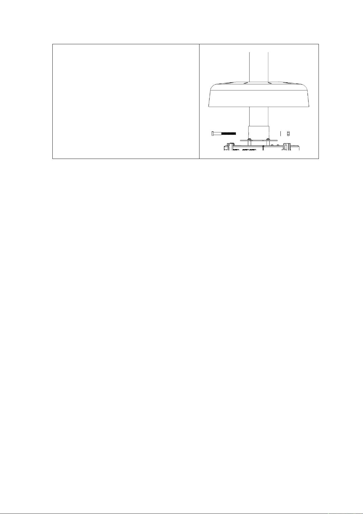
3.
Lift the top cover off TIM-1000 and undo the
nut and washer.
Take care while pulling the bolt out that the
unit is supported from the bottom.
Soulevez le couvercle supérieur du TIM1000 et desserrez l’écrou et la rondelle.
Assurez-vous que l’appareil est soutenu
par le bas lorsque vous tirez le boulon.
3.7 TIM-1000 Power up sequence
When a PoE cable from a live PoE network switch is applied to TIM-1000’s PoE port, the unit powers
up indicating the following sequence.
1. The LED ring turns Orange indicating that unit has power and is going through its self-test;
2. After approximately 20 seconds the Orange LEDs go OFF for approximately 15 seconds;
3. The LED ring turns Green indicating that it is ready for use;
4. If the LED ring’s default colour had been altered, those colours will be displayed.
Page 12 of 35
V1.2 2019-06
Page 21

4 Feature Description
TIM-1000 has a number of features that are quite unique. These features are described below.
Bring up the web GUI of the product. By default, the home tab will be in focus. Before you can log
into the GUI to gain access, password is required. The default password is “clockaudio” for both the
Home and Advanced pages. These passwords can be changed from the Advanced tab with different
passwords allocated for both the Home and Advanced tab.
To change passwords, on TIM-1000’s web GUI, click on the Advanced tab and log in. At the bottom
right hand side of the GUI, click on change password. This will pop-up another window with radio
buttons. Click on the Home or Advanced tab to set the password for the appropriate tab.
Featuring adjustable Adaptive Proximity Tracking (APT) technology, TIM-1000 tracks the person or
sound source within the room automatically and equalises the levels of the sound sources. This
enables a quieter sounds in the room to normalise the sound levels.
For cases where there may be some unwanted steady state noise in the room, e.g. from a projector,
air-conditioning, fan, rain, etc., TIM-1000 features a powerful noise suppression functionality that
virtually removes the steady state noise to provide a clear and clean output.
For cases where the corporate board rooms want to change the colour of the LEDs in the ring, a user
definable colour pallet is available.
3 x RJ45 ports are provided on the device. One port is for POE and provides connectivity to the
Dante network. The second port is for control network while the third port is daisy chaining the
control network to another TIM-1000. Up to 4 TIM-1000s can be daisy-chained.
V1.2 2019-06
Page 13 of 35
Page 22
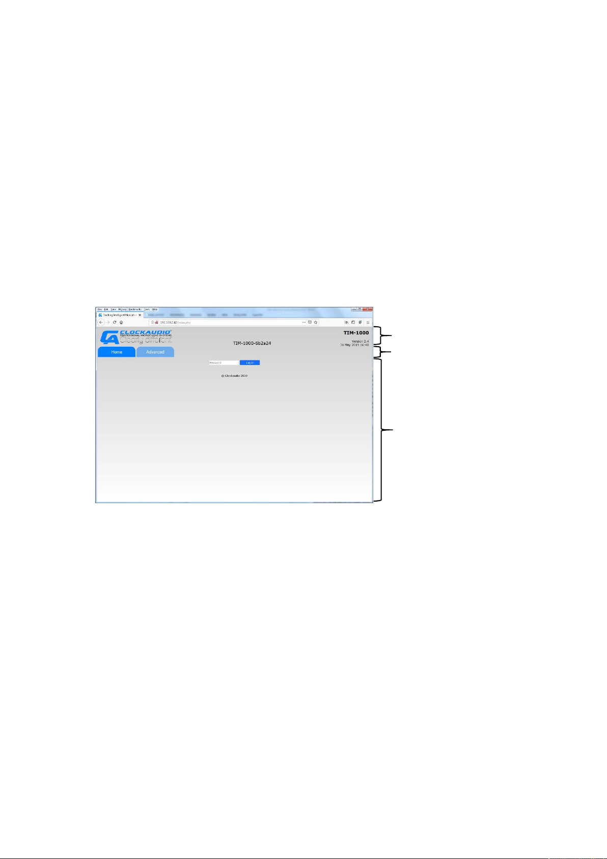
5 Understanding the GUI and Features
Section 1
Section 2
Section 3
The section below describes all the features of TIM-1000’s GUI and what each one does. When you
initially open TIM’s GUI using your favourite browser (compatible browsers are Microsoft Edge,
Internet Explorer, Safari, Firefox and Chrome), you are presented with a screen with two tabs –
Home and Advanced. By default the Home tab is highlighted. When you enter the password for the
selected tab, you’re logged into that part of the GUI. Every time a different Tab is selected, the
appropriate password will have to be re-entered. The GUI is split into 3 sections.
Section 1 has the Clockaudio logo, Generic product name (TIM-1000), Product name that will
appear to the control system (e.g. Dante network), s/w version number, date and time.
Section 2 displays two tabs – Home and Advanced.
Section 3 displays the features under the appropriate tab once you’ve logged in.
5.1 Passwords
Before you can log into the GUI to gain access, the password is required. The default password is
“clockaudio” for both the Home and Advanced pages. Passwords can be changed from the
Advanced tab where, if required, different passwords can be allocated to both the Home and
Advanced tab. See section on Password reset via GUI.
Page 14 of 35
V1.2 2019-06
Page 23
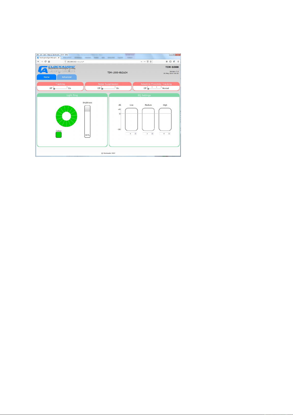
5.2 Home Tab
This Tab is what most users will use. Sections of this tab are:
5.2.1 Tracking
This is a slider that enables tracking to be turned ON or OFF. Tracking OFF equates to the
microphone behaving as omni-directional. Tracking ON equates to the ability of TIM-1000 to track a
person around the room.
5.2.2 Noise Suppression
This is a slider that enables or disables steady state noise suppression from the output. You may still
have noise in the vicinity of TIM-1000 but that steady state noise is not transferred to the person at
the other end of the output.
5.2.3 APT
(Adaptive Proximity Tracking)
This feature has a slider that has four steps
OFF – No uplift is applied to the sound source that is further away to ensure that the sound
levels of the quietest one to the loudest one in the room are kept consistent.
1st stop – When this stop is selected, the quieter sound source is slewed at approximately
1.5dB/sec to the same level as that of the person talking close to the mic. If the quieter
person continues to talk, their sound source will eventually reach the same level as that of
the person talking close to the mic.
2nd stop – When this stop is selected, the quieter sound source will be slewed at
approximately 3.0dB/sec to the same level as that of the person talking close to the mic. If
the quiet talker continues, then they will reach the same output volume as the main speaker
quicker than before.
ON (last stop) – when this stop is selected, the quieter sound source will reach the same
volume as the main speaker at a slew rate of about 6dB/sec.
V1.2 2019-06
Page 15 of 35
Page 24
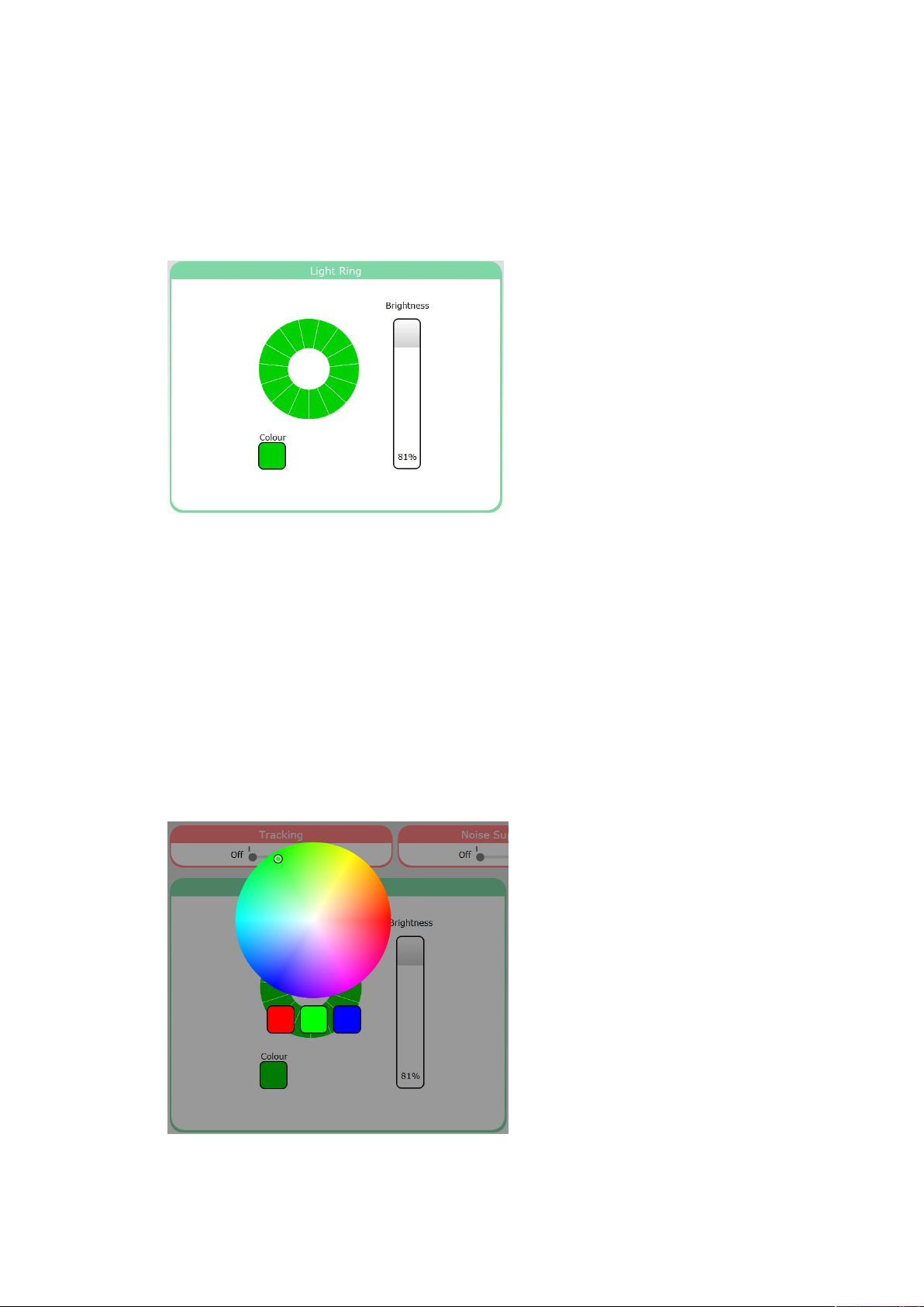
5.2.4 Light Ring
This provides the ability to set the colour of the light ring from the GUI.
Note: If the LED ring is required to illuminate different colours/brightness for different functions e.g.
active, mute… then UDP commands should be used program the LEDs colours.
On this GUI panel, there are two other panels.
Brightness – Clicking in this box and dragging the cursor down varies the brightness of the
colour ring on TIM-1000. As the cursor is dragged from the top of the box towards the
bottom, the panel’s display changes from white to a darker shade of grey. Brightness can be
varied from 100% (maximum brightness) down to 16% with its value displayed at the bottom
of the intensity panel. As the cursor is hovered over the box displaying the value, an “Off” is
displayed. Clicking in this section will set the LEDs to OFF. Thus allowing the LED ring to be
switched off completely.
Colour – Clicking in this box opens a colour pallet that allows the colour of the LED ring to be
chosen while the rest of the screen goes grey. Select the desired colour and click outside of
the colour wheel to exit. Quick access to set the LED ring for Red, Green or Blue, can be
achieved using the appropriate panel under the colour wheel.
Page 16 of 35
V1.2 2019-06
Page 25
5.2.5 EQ settings
These provide audio lift or reductions in the Low (0 – 350Hz), Mid (350 – 2000Hz) or High frequency
ranges (2000 – 8000Hz).
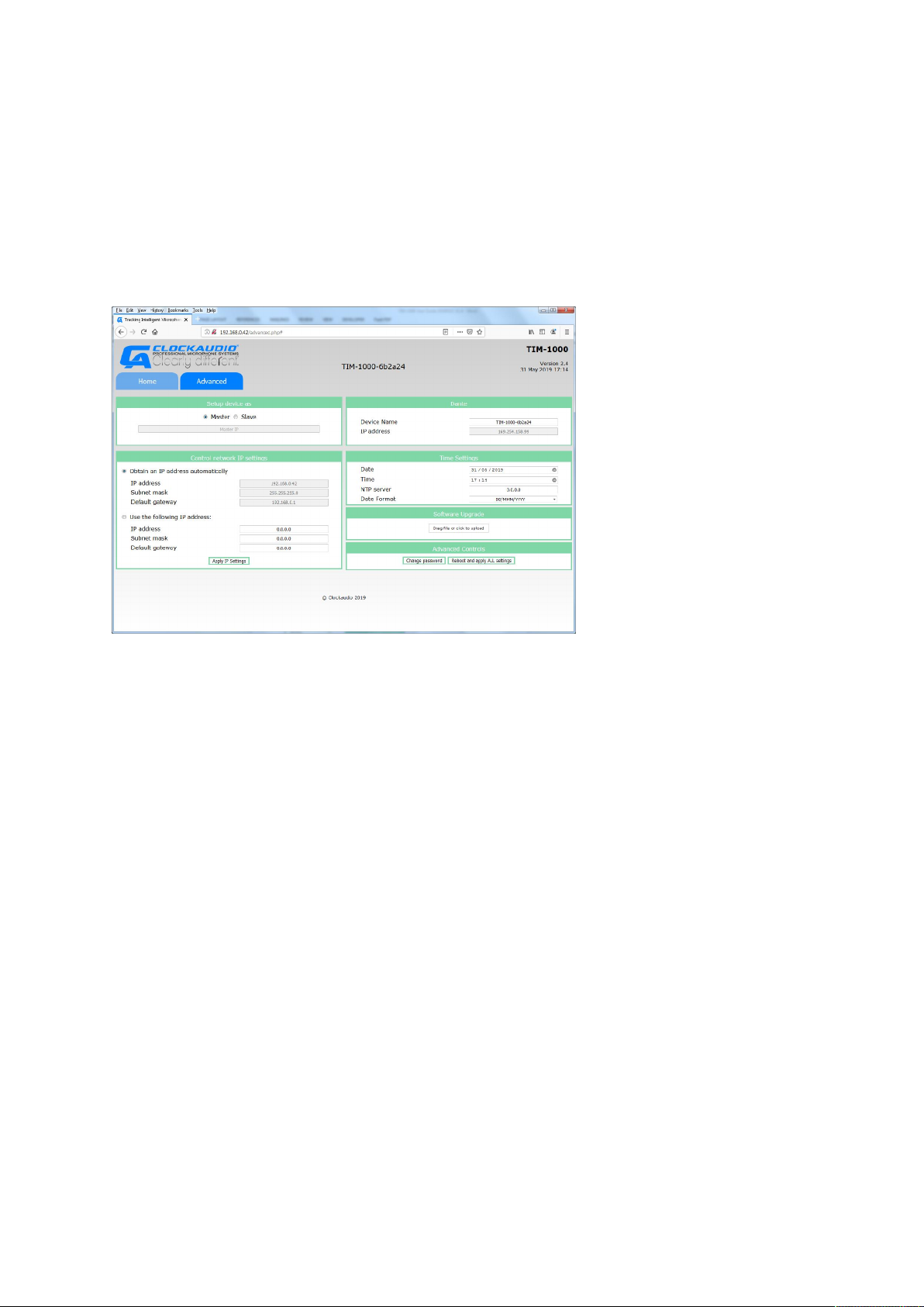
5.3 Advanced Tab
This tab is typically what an administrator, super user or IT department will use to configure the unit.
Sections of this tab are
5.3.1 Device setup
Allows TIM-1000 to be set as either Master or Slave unit. In general, if there is only one unit per
room, then it has to be set as a Master. However, for areas where you may need to use more than
one unit, the other unit(s) can be setup as a Slave device(s). When setup as a Slave, the Master units’
IP address must be entered in the GUI for each slave.
5.3.2 Control network IP settings
There are two ways for the unit to receive its control IP address – via DHCP or being set with a Static
IP. When “Obtain an IP address automatically” radio button is checked, TIM-1000 requests a DHCP
server to obtain the address. For this mode, there has to be a DHCP server available. If Static IP
needs to be set, select “Use the following IP address” radio button. When this is done, you’ll need to
specify the IP address of the unit, subnet mask and default gateway.
5.3.3 Dante Settings
This panel displays the current device’s network name (which can be edited) as well as the IP
address that will be used by Dante. This address would have either been negotiated through the link
local addressing or set through Dante Controller.
5.3.4 Time settings
This setting allows date and time to be set as long as the NTP address is 0.0.0.0. If the NTP address is
non-zero, TIM-1000 will use the specified NTP server to set the device’s date and time. The date
format allows you to select between the two date formats i.e. MMM/DD/YYYY or DD/MMM/YYYY.
V1.2 2019-06
Page 17 of 35
Page 26

5.3.5 Software upgrade
When new code is released, you can update the code on the unit by clicking in the box and browsing
to the appropriate section and selecting the file or by opening up the area where the file is located
and dragging it over into the box. Once done, the upgrade process will start. Stopping mid-way
during the process means no upgrade and product can be booted using the older version.
Latest software versions will be available from the www.clockaudio.com under TIM-1000.
5.3.6 Advanced controls
Two buttons are displayed here
“Change password” – Change password allows you to change passwords for the Home and
Advanced tabs. See section on changing “Password reset via GUI”.
“Reboot and apply ALL settings” – Reboot and apply ALL settings basically does what it says.
During the reboot process, contact with the server may disappear, and the GUI will need to be
restarted.
Note: Depending upon the DHCP server configuration, it may assign a different IP address to the
unit when rebooted.
Page 18 of 35
V1.2 2019-06
Page 27
5.4 Password Reset via GUI
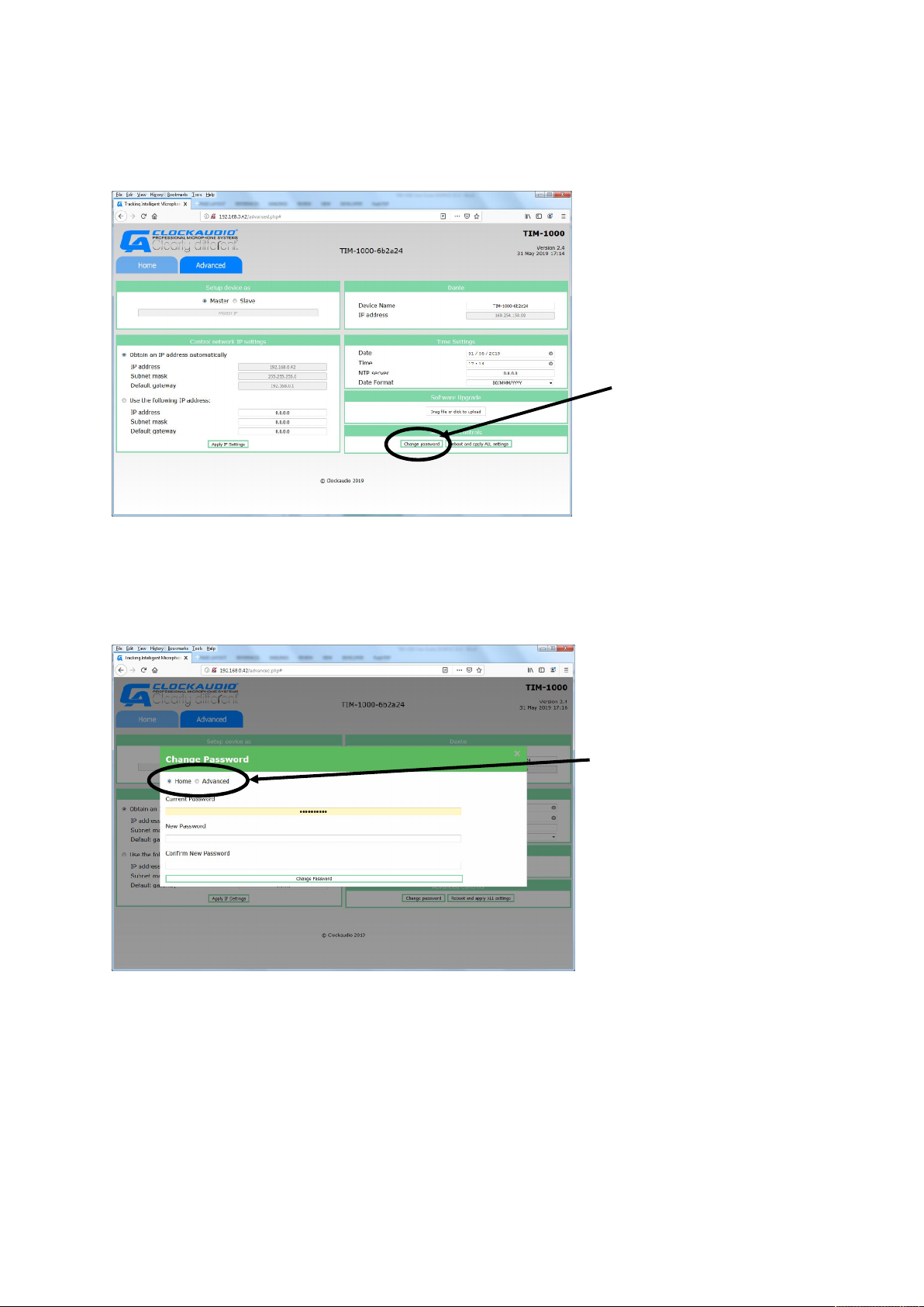
Click on this field to
Click on these radio buttons
To change passwords, bring up TIM-1000’s web GUI, click on the Advanced tab and log in with the
current password.
change passwords
At the bottom right hand side of the GUI, click on change password. The change password pop-up
window with radio buttons will appear. Click on the Home or Advanced tab to set the password for
the appropriate tab.
to change passwords for the
Home or Advanced tabs
Click on the appropriate tab and change, insert the new password that you wish to set TIM-1000 to
and click on Change Password.
V1.2 2019-06
Page 19 of 35
Page 28
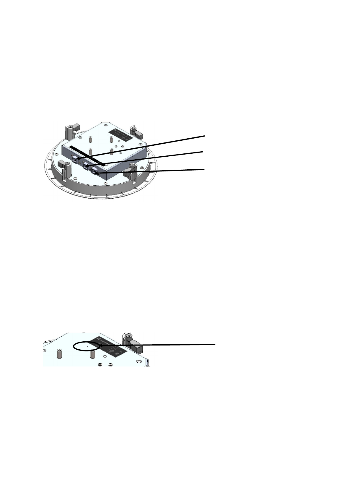
6 TIM-1000 Physical connections
PoE – Power over Ethernet
CTRL 1 – Control Port
CTRL 2 – for looping control
Reset to factory
This section describes the physical RJ45 ports and the Reset switch.
6.1 RJ45 Port Connections
Three RJ45 ports are available for connectivity of the product
line to next unit
• PoE – This port is the one that needs to be connected to the switch that can provide
Power over Ethernet and is also the one connected to the Dante network.
• CTRL1 – This port connects to the control network. It can be connected to the same as
the Dante network, but there is a flexibility in the product to have both the control and
Dante networks separate.
• CTRL2 – This port is used when you want to daisy chain a second device. This RJ45 port
connects to the CTRL1 port of the second device. You still have to run an independent
cable to connect the second unit’s Data port to the Dante network.
6.2 Factory Defaults Reset Switch
In the event of forgetting the passwords for the unit, a reset switch is provided on TIM-1000. This
reset switch is located on top of the unit and accessible via a pin hole.
defaults switch
It is important that care is taken to reset the unit as it will reset the unit back to factory default.
In order to perform a factory reset, remove the PoE connector and depress the switch using a pin
inserted into the hole. Then apply power to the unit while keeping switch depressed for at least 30
seconds and then release the switch.
TIM-1000 will then go through its default power-on sequence and boot up in the factory default
state.
Page 20 of 35
V1.2 2019-06
Page 29

7 Configuring TIM-1000
There is not a lot that needs to be configured for TIM-1000. The only things that can be configured
are:
• Tracking ON/OFF
• Noise Suppression ON/OFF
• APT
• Light Ring Colour
• EQ
• IP settings
• Date and Time
• Software upgrade
• Passwords
TIM-1000 as shipped from the factory is configured to accept DHCP. This means that the control port
when plugged into the network will receive its IP address from a DHCP server and when the PoE port
is plugged into the Dante network, it would negotiate a link local address.
If the IP addresses need to be changed, then the Control IP address can be changed by going into the
Advanced tab of the Web GUI and setting a static IP address. The IP address of the Dante port cannot
be changed from the Web GUI – this can only be changed through Dante Controller.
Date and Time can be set through the Advanced tab. If the NTP server’s IP address is 0.0.0.0 (i.e. set
as an invalid address), then the date and time fields can be used to set the time. If the NTP server
address is defined as a valid IP address, then TIM-1000 will attempt to contact the appropriate server
to look up and set the time.
If the passwords of the Home and/or Advanced tab are forgotten, not available or have been lost, then
it’s possible to perform a system reset. See section on Reset Switch on how to perform this action.
Software upgrade is a simple process and can be performed in one of two ways:
1. By dragging and dropping the software “tar” file that is supplied into the software upgrade
box on the Advanced tab
2. Clicking into the software upgrade box. This action will create a pop up on the window through
which you can navigate to the appropriate area where the “tar” file resides. Select the “tar”
file and click Open.
Once the software upgrade starts, TIM-1000 will lose connection to the network during the process
and the web GUI will become unresponsive. The whole upgrade process should take no longer than 5
minutes. If the web GUI does not refresh, it will need to be connected again.
It’s important to note that any changes (apart from Control IP address) made on the Advanced tab will
require clicking on the “Reboot and apply ALL settings” button. When this is done, TIM-1000 may lose
contact with the server, but depending upon the network configuration the GUI should refresh after
a short while.
V1.2 2019-06
Page 21 of 35
Page 30

7.1 Additional TIM-1000 configuration
When additional units are installed in a single conference room, they can be configured either in a
Master/Slave mode or as independent units.
Regardless of what mode is used, each additional unit shall produce a single Dante channel. It will be
up to the DSP to select the channel.
Configuring TIM-1000 to operate in a Master/Slave mode:
1. Set the radio button on the Advanced tab of the main unit as the Master.
2. On the additional unit(s), set the radio button on the Advanced tab as Slave.
3. Underneath the radio button, enter the Master units IP address for each slave unit(s).
Once configured, the slave units listen on the IP ports of the master unit for commands going to the
master. Any relevant commands, e.g. change of light colours, Tracking ON/OFF, Noise suppression
ON/OFF, APT settings and/or EQ settings, will be mirrored by the slave units.
Even if the units are going to be located in the same room, it is not necessary to configure them to
operate in Master/Slave mode as each unit will supply a separate Dante stream that needs to be
selected by the downstream DSP.
Whether the unit is working in a Master/Slave mode or not, each unit shall require its own Control
network and Data network IP addresses.
7.2 Configuring TIM-1000 on Dante networks
TIM-1000 presents itself as a single channel transmit device on Dante Controller. If the single channel
is required to connect to multiple locations, it can be configured using Dante Controller.
Page 22 of 35
V1.2 2019-06
Page 31

8 Troubleshooting
1. Unit not powering up
2. LED ring on TIM-1000 pulsing RED
3. TIM-1000 not showing up on Dante
4. Cannot load the web GUI
The following table describes some of the common faults and how to rectify them
network
Ensure that the RJ45 cable is at least Cat5e with all
8 pins connected.
Ensure that the network switch TIM-1000 is
plugged into is powered up and delivering Power
over Ethernet on the connected port.
Ensure that the Cat 5e cable is plugged into the PoE
port on TIM-1000.
If a PoE injector is used, ensure that it is plugged in,
powered and delivering PoE.
Ensure that there is minimum of 42 volts DC
available at the end of the RJ45 cable that plugs
into TIM-1000 and that the PoE switch or Injector is
capable of delivering a minimum of 8W.
Ensure that a correct and tested Cat5e cable is
being used.
Fault on unit. Please contact your dealer for repair.
Check the network settings for the Dante network.
Ensure that the network switch is connected to the
correct network and configured correctly.
TIM-1000 uses Link Local addressing to get its IP
address. Link local negotiates address in the range
of 169.254.x.x.
If using Microsoft Windows then you should see
TIM-1000 as a network resource on the control IP
network. Right click on the device and open up the
web page.
Ensure that you have access to the same sub-net as
TIM-1000 and that there are no firewalls
preventing connections.
Ensure that you can Ping TIM-1000 over the control
network. If not there may be a network issue and
you’ll have to call your network administrator.
Ensure that there is DHCP server available to
provide the IP address to TIM-1000. As shipped
from the factory, both Data and Control ports
require DHCP addressing.
V1.2 2019-06
Page 23 of 35
Page 32

9 Factory Configuration
Factory setting or
Reset via UDP
After s/w install
Power-on reset
Tracking
ON
ON
Retained as set
Retained as set
Noise
ON
ON
Retained as set
Retained as set
APT
OFF
OFF
Retained as set
Retained as set
EQ settings
Low, Mid and High
Low, Mid and
Retained as set
Retained as set
Unit set as
Master
Master
Retained as set
Retained as set
Control IP
DHCP
Retained as set
Retained as set
Retained as set
Dante IP
DHCP
Retained as set
Retained as set
Retained as set
Product name
TIM-1000-<last six
Retained as set
Retained as set
Retained as set
Time
07-Jan-2019 10:10
Retained as set
Retained as set
Retained as set
NTP server
0.0.0.0
0.0.0.0
Retained as set
Retained as set
Date format
DD/MMM/YYYY
Retained as set
Retained as set
Retained as set
Colour of LED
GREEN after boot
GREEN after boot
Retained as set
Retained as set
The following table describes the status of the TIM-1000 after reset.
after Button Reset
Suppression
address
address
all set to “0”
digits of Mac
Address>
am
High all set to “0”
Page 24 of 35
V1.2 2019-06
Page 33

10 Specifications
Ceiling Mount
Pole Mount
Dimensions
270mm circular x 75mm high
270mm circular x 150mm high
Weight
3 lbs (1.35 Kg)
Approx. 4.5lbs (2.0kg)
Ports
3 x RJ45 (1 port requires PoE other 2 Standard ports)
Connectivity
Use a standard Shielded Cat5e or better
Power (supplied via PoE)
Voltage 42 – 57V DC, 8W
Operating Temperature
0 to 40 degC
Storage Temperature
-20 to 60 degC
Relative Humidity
10 to 90% non-condensing
Frequency response
150 to 15000 Hz
Safety Certifications
IEC/EN 62368-1
IEC/EN 62368-1
EMC
EN 55032, EN 55035
10.63” circular x 2.95” high
(IEEE 802.3at-2009)
CE Mark
FCC Part 15b
CAN ICES-3 (B)/NMB-3(B)
10.63” circular x 5.90” high
CE Mark
V1.2 2019-06
Page 25 of 35
Page 34

11 Programming using UDP commands
UDP commands are the preferred method of communication between a control system (Crestron,
AMX, etc.) or DSP and Clockaudio’s TIM-1000 product. The section below defines a comprehensive
list of all UDP commands that TIM-1000 supports for configuration and management.
UDP commands are sent as ASCII character string with spaces used to delimit fields within a
command. The entire command is delimited with a Carriage Return. Whenever a command is sent
to the device, all acknowledged commands are returned with the command data with the string
“ACK” inserted preceding the command data.
If the device could not process a command then the command is returned with a “NACK” followed
by the string of data that was sent. NACKs are always returned for unknown commands, commands
with fewer parameters than expected or commands with invalid parameters.
The following sections describe the UDP command handling and the commands that are available
for TIM-1000. The default port number utilised for the UDP command is set to 49494.
All commands shall follow the following rule:
<COMMAND><Space><PARAM 1><Space><PARAM 2><Space>…<PARAM 6><CR>
Where: <COMMAND> is the actual command sent to the device
<Space> is a space character (20H from the ASCII Table) sent to the device
<PARAM 1> is the first parameter sent to the device
<PARAM 2> is the second parameter sent to the device
:
<PARAM 6> is the sixth parameter sent to the device
<CR> is the carriage return character (0DH from the ASCII Table) sent to the device
NOTES:
1. It is important that only a single space character is inserted between <COMMAND> and
<PARAM 1> as well as between each parameters.
2. An invalid <COMMAND>, value of any <PARAM x> and/or additional spaces inserted shall
result in the entire command being rejected. In that case a “NACK” followed by the string
sent shall be returned from the device.
3. Depending upon command syntax, a carriage return shall immediately follow the
<COMMAND> or the final parameter for the command.
4. Transmission of insufficient parameters for the command shall result in the entire
command being rejected. In that case a “NACK” followed by the string sent shall be
returned from the device.
5. It shall be acceptable to have either no space or a single space character at the end of a
completed UDP command; more than one space shall result in command being rejected
and a “NACK” returned.
Page 26 of 35
V1.2 2019-06
Page 35

11.1 ID (Identify Unit)
Definition
The Identify command is used to permit a given unit to be physically identified.
Syntax
ID <Space> <PARAM 1> <CR>
PARAM 1
Defines whether LED flashes
PARAM 2
This parameter is not required. Carriage return shall follow immediately after
Example(s)
To set Identify on
Device
The following response shall be received from the device
Definition
The Find Unit command is used to permit a given unit to be physically identified.
Syntax
FU<CR>
PARAM 1
This parameter is not required. Carriage return shall follow immediately after
PARAM 2
This parameter is not required.
Example(s)
To Find unit
Device
The following response shall be received from the device
It causes the Power LED on the unit to flash at an approximate rate of 330
milliseconds for ON and same for OFF.
Identify command has an ON / OFF parameter and remains in the selected state
until a new Identify command (or reset event) is sent to change state.
0 = OFF
1 = ON
Parameter 1.
Ex 1: ID 1<CR>
response(s)
Res 1: ACK ID 1<CR>
11.2 FU (Find Unit)
It causes the Power LED to flash at an approximate rate of 330 milliseconds for
ON and same for OFF.
The Find Unit command shall flash the Power LED for 5 seconds only after which
the Power LED function shall then resume without the need for sending any
additional commands.
the Command.
Ex 1: FU<CR>
response(s)
Res 1: ACK FU<CR>
V1.2 2019-06
Page 27 of 35
Page 36

11.3 VERSION (Version)
Definition
The VERSION command returns the current version of the Host firmware. The
Syntax
VERSION <CR>
PARAM 1
This parameter is not required. Carriage return shall follow immediately after
PARAM 2
This parameter is not required.
Example(s)
To request firmware version
Device
The following response shall be received from the device
Definition
The DEFAULTS command sets TIM-1000 to a known default state on all settings
Syntax
DEFAULTS <CR>
PARAM 1
This parameter is not required. Carriage return shall follow immediately after
PARAM 2
This parameter is not required.
Example(s)
To request firmware version
Device
The following response shall be received from the device
command has no parameters.
The VERSION command only returns the version of the Host MCU firmware. For
the version of the Ultimo (Dante) firmware the Dante Controller application shall
be used.
the Command.
Ex 1: VERSION<CR>
response(s)
Res 1: ACK VERSION x.y<CR>
Where “x” indicates the major version number and “y” the minor version
number of the Host’s MCU firmware
11.4 DEFAULTS (Defaults)
(see section on Factory Configuration).
the Command.
Ex 1: DEFAULTS<CR>
response(s)
Res 1: ACK DEFAULTS<CR>
Page 28 of 35
V1.2 2019-06
Page 37

11.5 STS (Set TS State)
Definition
The STS State command provides for setting the state of the Red, Green or Blue
Syntax
STS <Space> <PARAM 1> <Space> <PARAM 2> <CR>
PARAM 1
This parameter defines the port for which the status is required.
PARAM 2
This parameter defines the state of the LED for values of R, G or B
Example(s)
To set the state
Device
The following response shall be received from the device
Definition
The Get TS status command is used to retrieve the logic input / output state of
Syntax
GTS <Space> <PARAM 1> <CR>
PARAM 1
This parameter defines the port for which the status is required.
PARAM 2
This parameter is not required. Carriage return shall follow immediately after
Example(s)
To request LED status
Device
The following response shall be received from the device
LEDs on either all or a selected LED.
0 = All LEDs
1..15 = Specific LED
0 = OFF
1 = ON
Ex 1: STS 0 R=1<CR> ; sets RED LED ON for all LEDs
Ex 2: STS 1 R=0<CR> ; sets RED LED OFF for LED 1 only
Ex 3: STS 3 G=1<CR> ; sets GREEN LED ON for LED 3 only
Ex 4: STS 4 B=1<CR> ; sets Blue LED ON for LED 4 only
response(s)
Res 1: ACK STS 0 R=1<CR> ; Red LED set to ON for all LEDs
Res 2: ACK STS 1 R=0<CR> ; Red LED set to OFF on LED 1 only
Res 3: ACK STS 3 G=1<CR> ; Green LED set to ON for LED 1 only
Res 4: ACK STS 4 B=1<CR> ; Blue LED set to ON for LED 4 only
11.6 GTS (Get TS Status)
either ALL or a selected LED. The data is formatted similarly for each channel
0 = All LEDs
1..15 = Specific LED
Parameter 1.
Ex 1: GTS 0<CR> ; requests status for all LEDs
Ex 2: GTS 2<CR> ; requests status for LED 2 only
response(s)
Res 1: ACK GTS 0 CH1R=0 CH1G=1 CH1B=1 CH1SC=0 ……
CH15R=1 CH15G=1 CH15B=1 CH15SC=1<CR>
Res 2: ACK GTS 2 CH2R=0 CH2G=1 CH2B=1 CH2SC=1<CR>
CHxR=y provides the current state for channel x Red LED, y = 0 for inactive, 1
for active
CHxG=y provides the current state for channel x Green LED, y = 0 for
inactive, 1 for active
CHxB=y provides the current state for channel x Blue LED, y = 0 for inactive,
1 for active
CHxSC=y For TIM-1000 y=0
V1.2 2019-06
Page 29 of 35
Page 38

11.7 STSB (Set TS Brightness)
Definition
The STSB command provides for setting the brightness of the Red, Green or Blue
Syntax
STSB <Space> <PARAM 1> <CR>
PARAM 1
This parameter defines the LED number
PARAM 2
This parameter defines the brightness levels implemented as a “duty cycle”. The
Example(s)
To set brightness
Device
The following response shall be received from the device
Definition
The Get TS brightness command is used to retrieve the brightness level of either
Syntax
GTS <Space> <PARAM 1> <CR>
PARAM 1
This parameter defines the LED number.
PARAM 2
This parameter is not required. Carriage return shall follow immediately after
Example(s)
To request brightness level
Device
The following response shall be received from the device
LEDs on either ALL or a selected LED.
The brightness levels are implemented as a “duty cycle”. The duty cycle is set in
10% increments so valid values are 10, 20, 30, 40, 50, 60, 70, 80, 90 and 100.
0 = All LEDs
1..15 = Specific LED
duty cycle is set in 10% increments so valid values are 10, 20, 30, 40, 50, 60, 70,
80, 90 and 100
Ex 1: STSB 0 R=50<CR> ; sets Red to 50% brightness on all LEDs
EX 2: STSB 1 G=70<CR> ; sets Green to 70% brightness on LED 1 only
Ex 3: STSB 4 B=90<CR> ; sets Blue to 90% brightness on LED 4 only
response(s)
Res 1: ACK STSB 0 R=50<CR>
Res 2: ACK STSG 1 R=70<CR>
Res 3: ACK STSB 4 R=90<CR>
11.8 GTSB (Get TS Brightness)
ALL or a selected LED.
0 = All LED
1..15 = Specific LED
Parameter 1.
Ex 1: GTSB 0<CR> ; requests brightness level for all LEDs
Ex 2: GTSB 2<CR> ; requests brightness level for LED 2 only
response(s)
Res 1: ACK GTSB 0 CH1R=50 CH1G=30 CH1B=30 ……
CH15R=10 CH15G=100 CH15B=100<CR>
Res 2: ACK GTSB 2 CH2R=50 CH2G=100<CR>
CHxR=y provides the brightness level for channel x Red LED, y = 10..100
CHxG=y provides the brightness level for channel x Green LED, y = 10..100
CHxB=y provides the brightness level for channel x Blue LED, y = 10..100
Page 30 of 35
V1.2 2019-06
Page 39

11.9 SRGB (Set RGB State)
Definition
The SRGB State command provides a more granular level for setting the
Syntax
SRGB <Space> <PARAM 1> <Space> <PARAM 2> <CR>
PARAM 1
This parameter defines the LED number.
PARAM 2
This parameter specifies the intensity level for each RGB colour as a decimal
Example(s)
To set RGB values
Device
The following response shall be received from the device
Definition
The GRGB State command retrieves the brightness of the Red, Green and Blue of
Syntax
GRGB <Space> <PARAM 1> <CR>
PARAM 1
This parameter defines the LED number.
PARAM 2
This parameter is not required. Carriage return shall follow immediately after
Example(s)
To request RGB status
Device
The following response shall be received from the device
brightness of the Red, Green and Blue LEDs in the LEDs
0 = All LEDs
1..15 = Specific LED
value of 8 bits i.e. 0 through 255
Ex 1: SRGB 0 255 255 255<CR> ; set Red, Green and Blue LEDs to full intensity
on all LEDs
Ex 2: SRGB 1 128 0 255<CR> ; set Red to 50%, Green to 0% and Blue to 100%
intensity on LED 1
response(s)
Res 1: ACK SRGB 0 255 255 255<CR>
Res 2: ACK SRGB 1 128 0 255<CR>
11.10 GRGB (Get RGB State)
either ALL or a selected LED.
0 = All LEDs
1..15 = Specific LED
Parameter 1.
Ex 1: GTS 0<CR> ; requests RGB status for all LEDs
Ex 2: GTS 2<CR> ; requests RGB status for LED 2 only
response(s)
Res 1: ACK GRGB 0 CH1 200 167 167 …... CH15 67 95 100<CR>
Res 2: ACK GRGB CH2 128 128 250<CR>
V1.2 2019-06
Page 31 of 35
Page 40

11.11 APT (Set APT)
Definition
The APT command determines the amount of Adaptive Proximity Tracking. It
Syntax
APT <Space> <PARAM 1> <CR>
PARAM 1
This parameter defines how the product slews to the sound source.
PARAM 2
This parameter is not required. Carriage return shall follow immediately after
Example(s)
To set APT to NORMAL
Device
The following response shall be received from the device
Definition
The TRACKING command enables or disables the tracking function.
Syntax
TRACKING <Space> <PARAM 1> <CR>
PARAM 1
This parameter turns tracking ON or OFF.
PARAM 2
This parameter is not required. Carriage return shall follow immediately after
Example(s)
Ex 1: TRACKING 1<CR> ; enables tracking functionality of the microphone
Device
The following response shall be received from the device
defines the rate at which the product slews to the sound source; when set to
normal the furthest sound source appears as clear as the nearest.
0 = OFF ; TIM-1000 works without any proximity tracking
1 = SLOW ; Tracks at a slew rate of approx. 1dB/sec
2 = MEDIUM ; Tracks at a slew rate of approx. 3dB/sec
3 = NORMAL ; Tracks at a slew rate for best possible sound
If this parameter is omitted, then unit shall return state of APT.
Parameter 1.
Ex 1: APT 3<CR> ; sets APT to NORMAL
Ex 2: APT <CR>; inquires status of APT
response(s)
Res 1: ACK APT 3<CR>
Res 2: ACK APT x<CR> ; where “x” indicates state of APT
11.12 TRACKING (Tracking Mode)
0 = OFF ; allows microphone to work as an Omni
1 = ON ; enables tracking mode
If this parameter is omitted, then unit shall return state of TRACKING.
Parameter 1.
Ex 2: TRACKING <CR> ; inquires state of unit’s TRACKING mode
response(s)
Res 1: ACK TRACKING 1<CR>
Res 2: ACK TRACKING x<CR> ; where “x” indicates state of TRACKING
Page 32 of 35
V1.2 2019-06
Page 41

11.13 EQ (EQ Settings)
Definition
The EQ command sets the values for each of the equaliser bands on TIM-1000.
Syntax
EQ<Space><PARAM 1><Space><PARAM 2><CR>
PARAM 1
This parameter defines whether it’s the LOW, MEDIUM or HIGH frequency that
PARAM 2
This parameter defines the value for each of the PARAM 1 settings. The range
Example(s)
To set EQ settings
Device
Res 1: ACK EQ 0 +4<CR>
Definition
The NOISESUP command defines whether the ambient noise suppression is
Syntax
NOISESUP <Space> <PARAM 1> <CR>
PARAM 1
This parameter defines whether noise suppression is OFF or ON.
PARAM 2
This parameter is not required. Carriage return shall follow immediately after
Example(s)
To set noise suppression
Device
The following response shall be received from the device
needs to be set
0=LOW frequency setting
1=MEDIUM frequency setting
2=HIGH frequency setting
shall be from +6dB to -20dB. The values shall be integer values.
If this parameter is omitted, then unit shall return EQ value of PARAM 1
Ex 1: EQ 0 +4<CR> ; defines LOW frequency setting at +4dB
Ex 2: EQ 1 -10<CR> ; defines MEDIUM frequency setting at -10dB
Ex 3: EQ 0 <CR>; inquires EQ state of the LOW frequency setting
response(s)
Res 2: ACK EQ 1 -10<CR>
Res 3: ACK EQ 0 x<CR> ; where “x” indicates EQ value of LOW frequency
settings
11.14 NOISESUP (Noise Suppression)
enabled or disabled
0 = OFF
1 = ON
If this parameter is omitted, then unit shall return state of NOISESUP
Parameter 1.
Ex 1: NOISESUP 1<CR> ; enables noise suppression
Ex 2: NOISESUP <CR> ; inquires unit’s state of noise suppression
response(s)
Res 1: ACK NOISESUP 1<CR>
Res 2: ACK NOISESUP x <CR> ; where “x” indicates status of noise suppression
V1.2 2019-06
Page 33 of 35
Page 42

12 Product Warranty
This product is offered with a 1 year warranty from the date of purchase. Any defect that arises due
to faulty materials or workmanship will either be replaced, or repaired free of charge by the agent
from whom you purchased the unit. Please note charges will be incurred on any products returned
for service / repair not in warranty or have been subject to customer abuse or incorrect wiring.
The warranty is subject to the following provisions:
The warranty does not cover accidental damage, misuse, cabinet parts, knobs, batteries or
consumable items. Any product returned to Clockaudio failing to meet the terms listed will
incur a repair and carriage charge.
The product must be correctly installed and operated in accordance with the instructions
supplied with the product.
Unauthorised modifications and alterations to the original specifications will render the
warranty void.
The product must be used for the sole purpose that it was designed for.
The warranty given is strictly with the original owner and becomes invalid if the product is
resold or becomes damaged by inexpert repair.
Product purchased outside of the countries served by Clockaudio designated / approved
agents are not covered by the warranty.
Specifications / improvements are subject to change without notice.
Clockaudio disclaims any liability for incidental or consequential damages.
The warranty is in addition to and does not diminish your statutory legal rights.
Page 34 of 35
V1.2 2019-06
Page 43

13 Product Disposal
Corporate Headquarters:
Clockaudio Limited,
Subsidiaries:
Clockaudio North America Inc.
Clockaudio Pte. Ltd
At the end of the life of this equipment, dispose of equipment according to local regulations
For more information and advice on Clockaudio products please visit the Clockaudio website:
www.clockaudio.com
Wellington Gate,
Silverthorne Way,
Waterlooville,
Hampshire, PO7 7XY,
United Kingdom
Tel: +44 23 92251193
2891 Rue du Meunier,
Unit 103, Vaudreuil Dorion,
Quebec, J7V 8P2,
Canada
Tel: + 1 450 4249797
Fax: + 1 450 4243660
BizTech Centre,
Unit #01-02,
627A Aljunied Road,
Singapore 389842
Tel: +65 67484738
Fax: +65 67484428
V1.2 2019-06
Page 35 of 35
Page 44

 Loading...